Go to fetco.com for the latest versions of all information Page 4P112 Revised November 2021
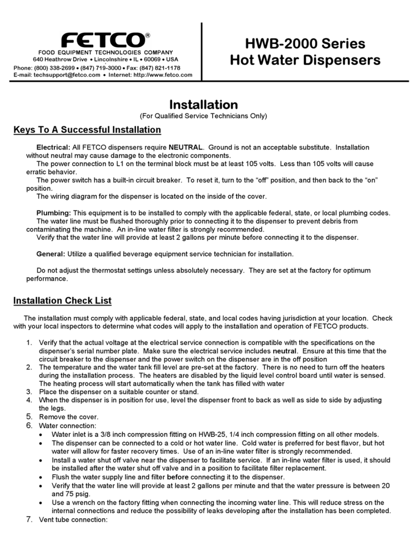
Keys To A Successful Installation
(For Qualified Service Technicians Only)
Electrical:
All FETCO dispensers require NEUTRAL. Ground is not an acceptable substitute. Installation without neutral, or
attaching a powered lead, may cause damage to the electronic components.
The power connection to L1 on the terminal block must be at least 105 volts. Less than 105 volts will cause erratic
behavior. Greater than 120 volts may damage the equipment.
The power switch has a built-in circuit breaker. To reset it, turn to the “off” position, and then back to the “on” position.
The wiring diagram for the dispenser is located on the inside of the cover.
Plumbing:
This equipment is to be installed to comply with the applicable federal, state, or local plumbing codes.
The water line must be flushed thoroughly prior to connecting it to the dispenser to prevent debris from contaminating
the machine. All beverage equipment should use an inline water filter.
Verify that the water line will provide at least 2 gallons per minute before connecting it to the dispenser.
General:
Utilize only qualified beverage equipment service technicians for installation. A Service Company Directory may be
found on our web site, http://www.fetco.com. Or at https://www.fetco.com/pl,service-technicians,service.html
Do not adjust the thermostat settings unless absolutely necessary. They are set at the factory for optimum
performance.
Installation Check List
The installation must comply with applicable federal, state, and local codes having jurisdiction at your location. Check
with your local inspectors to determine what codes will apply to the installation and operation of FETCO products.
1) Verify that the actual voltage at the electrical service connection is compatible with the specifications on the
dispenser’s serial number plate. Make sure the electrical service includes neutral. Ensure at this time that the
circuit breaker to the dispenser and the power switch on the dispenser are in the off position
2) The temperature and the water tank fill level are pre-set at the factory. There is no need to turn off the heaters
during the installation process. The heaters are disabled by the liquid level control board until water is sensed.
The heating process will start automatically when the tank has filled with water
3) Place the dispenser on a suitable counter or stand ( Note filled weights from chart on page 2)
4) When the dispenser is in position for use, level the dispenser front to back as well as side to side by adjusting
the legs.
5) Remove the cover
6) Water connection
Water inlet is a 3/8 inch male flare fitting
The dispenser can be connected to a cold or hot water line. Cold water is preferred for best flavor, but hot water
will allow for faster recovery times. Use of an in-line water filter is strongly recommended
Install a water shut off valve near the dispenser to facilitate service. If an in-line water filter is used, it should be
installed after the water shut off valve and in a position to facilitate filter replacement.
Flush the water supply line and filter before connecting it to the dispenser.
Verify that the water line will provide at least 0.75 gallons per minute and that the water pressure is
between 20 and 75 psig.
Use a wrench on the factory fitting when connecting the incoming water line. This will reduce stress on the internal
connections and reduce the possibility of leaks developing after the installation has been completed.
7) .Vent tube connection:
Vent tube connection is a ⅜inch hose barb.
Tank vent must never be obstructed. It is to normalize the hot water tank pressure to fill and dispense water. The
hot water tank is not pressurized - this is an atmospheric hot water dispense system. If a condensate drain is
desired: use heavy wall or rigid tubing with a minimum ⅜ inch ID. Do not plumb to drain-leave a minimum 12” air
