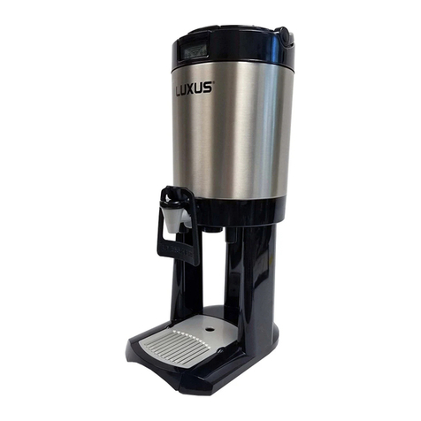
Fetco INNOTHERM L4-HD15 Specifications

www.fetco.com User’s Guide and Operator Instructions
INNOTHERM™
Heated LUXUS
®
Thermal Dis
p
ensers & Servers
FEATURES
-Works with all 1.5 gallon FETCO coffee brewers
Works with most brewers-use your existing equipment!
>
-No base required-Save on additional equipment costs.
-Portability-Plug‐in or transport to anywhere.
-Gentle heating to help preserve taste profiles
-Fully insulated to help with heat retention.
-Fully sealed heating system
-Built‐in programmability for time and temperature
Program user settings without dismantling the unit.
-LED status indicator on front of INNOTHERM
Multi
‐
Color LED for quick reference.
INNOTHERM DISPENSERS
Weights & Capacities
INNOTHERM SERVERS
Weights & Capacities
HEIGHT
WIDTH
LENGTH (BASE)
HEIGHT
WIDTH
LENGTH (BASE)
23 in./584mm
9 in./230mm
13 in./335mm
14¾ in./374mm
9 in./230mm
12½ in./317mm
CAPACITY
WEIGHT-EMPTY
WEIGHT-FILLED
CAPACITY
WEIGHT-EMPTY
WEIGHT-FILLED
1.5 gallon/5.7 liter
11.3lb/5.1kg
23.8lb/10.8 kg
1.5 gallon/5.7 liter
7.2lb/3.3kg
17.6lb/8.0 kg
D467--
D477--
D478--
Heated INNOTHERM
Heated Serve
r
Heated Server and Stand
Required power suppl
y
FETCO Part # 1102.00278.00
Power suppl
y
output 24 VDC 2.0 Amp
DC output connector Center positive
Power suppl
y
input 100-240VAC 2.0Amp 50/60 Hz
Power configuration
40 Watts
Plug configuration NEMA 1-15
IMPORTANT NOTICE:
RE: Connecting & Disconnecting the Power Supply
-Disconnect power supply module before filling and cleaning.
-Reconnect power supply for beverage service
-Never expose the power supply module or wires to moisture
IMPORTANT NOTICE
-Use only FETCO Power Supply 1102.00278.00.
-This part has the correct over voltage/current / short circuit
protection.
INNOTHERM heated dispenser will operate in heating mode only
when connected to the plug-in power supply included with
dispenser and filled with heated liquid that is at least 145°F
Contact Information
FETCO®
Food Equipment Technologies Company
600 Rose Road
Lake Zurich • IL • 60047-1560 • USA
© 2018 Food Equipment Technolo
g
ies Compan
y
Internet: www.fetco.com
Phone: (800) 338-2699 (US & Canada)
(847) 719-3000
Fax: (847) 719-3001
techsupport
@
fetco.com P136 March, 2019
User programming interface
with indicating LED lights
Simple Magnetic Connector
…Bring together and “click”
WARNING!
Never expose power supply module or wires to moisture
Do not energize INNOTHERM dry or without cover/funnel
INNOTHERM must contain liquid above 145°F to operate
fetco.com

DEFINITIONS OF LED Li
g
ht COLORS
TIMER
GREEN LED
TEMPERATURE
RED LED
STATUS
BLUE LED
DURING STARTUP
1 flash-4 hours “ON”
2 flashes-8 hours “ON”
3 flashes -24 hours “ON”
(4 hours is factory set default)
24 hrs. is useful for hot water service
DURING STARTUP
1 flash-170°F/76.7°C
2 flashes-176°F/80°C
3 flashes-182°F/83.3°C
4 flashes =-188°F/86.7°C
(182°F is factory set default)
DURING STARTUP
(Inactive during startup)
AFTER STARTUP
Steady GREEN when operating
Blinks GREEN if empt
y
or cold
AFTER STARTUP
Steady RED after timeout
…Or when emptied
AFTER STARTUP
BLUE 15 min before timeout:
then chan
g
es to stead
y
RED
INNOTHERM HEATED DISPENSER OPERATION:
STARTUP
INNOTHERM is ready to operate as received. INNOTHERM must be filled with liquid at least 145°F to operate.
Always pre-heat INNOTHERM for best results. Brew at least one half full water only, hold 2-10 min & drain.
The INNOTHERM heater will hold the contents four hours at 182°F. At the end of the timer, the heater shuts off.
INNOTHERM may be user programmed to the settings above. Programming instructions are on the next page.
Turn INNOTHERM ON by connecting the magnetic power cord connector to the magnetic power receptacle located
on the right hand side of the INNOTHERM, between the front stand leg and the rear stand leg.
Once the power connection has been made INNOTHERM walk through the current programmed settings.
First INNOTHERM will flash the corresponding number of GREEN flashes indicating the current setting for TIME
(1 flash = 4 hours [DEFAULT], 2 flashes = 8 hours, 3 flashes = 24 hours). There are three TIME settings.
(After a 2 second pause)
Second: INNOTHERM will flash the corresponding number of RED flashes indicating the current setting for TEMP
(1 flash = 170° F setpoint, 2 flashes = 176° F, 3 flashes = 182° F [DEFAULT], 4 flashes = 188° F setpoint).
There are four TEMP settings.
INNOTHERM HEATED DISPENSER OPERATION:
OPERATION
Pre-heat cold INNOTHERM for best results. Brew ½ full water only, hold 2-10 min & drain
Once the TIME and TEMP setting indications are completed, the LED located in the front lower right-hand side will
begin flashing GREEN. This indicates that INNOTHERM is connected to power and is in the Idle mode
To activate the INNOTHERM heater, you must pour in hot liquid at 145° F temperature (or hotter).
When the heater is engaged the LED will change over to continuous GREEN
LED will remain continuous GREEN throughout the cycle TIME setting (Of 4 hours, 8 hours or 24 hours).
At 15 minutes remaining in the TIME cycle the LED will change from continuous GREEN to continuous BLUE
This is a notification to the operator that the end of the TIMED HEATING cycle is near.
At the end of the heating cycle TIME or when INNOTHERM is EMPTY, the LED changes to continuous RED
This indicates INNOTHERM timer has shut off the heater.
Attaching the Magnetic Connector acts as the ON/OFF switch
User programming interface
with indicating LED lights
Simple Magnetic Connector
…Bring together and “click”

INNOTHERM HEATED DISPENSER PROGRAMMING STEPS:
1. Connect power supply (magnetic power connection is located on right side of the dispenser).
ON STARTUP:
Whenever INNOTHERM is powered up, the unit displays the current TIME & TEMPERATURE setting
-Time is displayed by the number of GREEN LED flashes
-Temperature is displayed by the number of RED LED flashes.
2. To enter PROGRAM mode:
Power INNOTHERM “ON”
-At the end of the power up/settings reporting cycle (approximately 10 seconds), press and hold either
TIME or TEMP button.
The LED will turn BLUE indicating the Operator has successfully entered PROGRAM mode.
3. Release the button that was pressed, BLUE LED remains ON.
TIME: Green Flash
Press 1 time; then see 1 flash=4 hours “ON”
Press 2 times; then see 2 flashes=8 hours “ON”
Press 3 times; then see 3 flashes =24 hours “ON”
TEMPERATURE: Red Flash
Press
1
time, then see 1 flash = 170°F/76.7°C
Press 2 times, then see 2 flashes=176°F/80°C
Press 3 times, then see 3 flashes=182°F/83.3°C
Press 4 times, then see 4 flashes =188°F/86.7°C
4. Referring to the settings above:
While in programming mode-with the blue LED on…
Press either TIME or TEMP button the required number of times to set to new values for TIME or TEMP
EXAMPLE: If the operator presses TIME button 2 times (to set time for 8 Hours) BLUE LED goes off and
GREEN LED will flash 2 times and goes back to normal programming state, BLUE LED stays steady ON.
At this time operator can either press TIME button again to select different settings for TIME or press
TEMP button to set new settings for the temperature e.g.
EXAMPLE: If TEMP button is pressed for 4 times (to set TEMP for 188°F) BLUE LED goes off and RED
LED will flash 4 times then controls goes back to normal programming state, BLUE LED stays steady ON
5. TO SAVE Settings : Once the desired settings are selected then press and hold either TIME or TEMP
button for more than 5 seconds to save the current settings, then BLUE LED turns OFF, to indicate
programming is completed and INNOTHERM will automatically transition into working mode.
This is indicated by a solid or flashing GREEN LED (depending upon the state of the INNOTHERM cycle)
NOTES:
6. If either TIME or TEMP is pressed more than the allowed limit(Max 3 presses for TIME, 4 presses for
TEMP),then BLUE LED will flash faster for 2-3 seconds to indicate the setting entered by button presses
is out of range and goes back to normal programming state, BLUE LED stays steady ON.
7. If either TIME or TEMP button is pressed and held longer than 20 seconds, then it will detect it as stuck
key error and INNOTHERM will go into error state and RED LED will flash for X numbers of times to
enunciate stuck key error and INNOTHERM will stay in that mode until the power is recycled.
PRESS PRESS

INNOTHERM HEATED DISPENSER ERROR DIAGNOSTICS:
For Service and Repair.
An ERROR STATE will make the RED LED flash followed by a 2 second PAUSE and repeats the flashing pattern.
The dispenser will continue to be in error state until the power is switched OFF.
If ERRORS are detected--the dispenser will indicate current TIME and TEMPERATURE setting upon powering up.
After a 10 second window, the ERROR enunciation will continue, and the dispenser will be inoperable.
The followin
g
ERRORs are supported on this dispenser:
RED LED
Flashes
Error
Code Description Comments
1 1 Software Error : Setup corrupted Contact Service
2 2
Software Error :
Flash checksum
(
CRC
)
error Unit can't be recovered re-flash the firmware
3 3
Software Error :
Fatal software crash
Software crash for unknown reason
Re-cycle power may help
4 50 Short temperature probe Contact Service
5 51 Open temperature probe Contact Service
6 201 Heater Open +5°F/2.8C temperature change NOT detected in 30 min. since
heater turned ON.
7 255 Keyboard (Stuck Key) Key stuck for >20 seconds
This error is ONLY in programming mode NOT in normal mode
NOTE : RED LED flashes X times (depend on above error code) and then PAUSES 2 seconds
#Description Part Number
1
A
Cover Lid 1023.00277.00
1B Funnel Bail Handle 1023.00278.00
2 Funnel Top Cover 1023.00279.00
3 Handle With Hardware 1000.00112.00
4
A
Top Gaske
t
1029.00016.00
4B Bottom Gasket 1029.00015.00
5 Cover/ Funnel Assembl
y
1109.00109.00
6 Funnel Plu
g
(
Qt
y
-4
)
1029.00010.00
7 Indicator Funnel 1102.00149.00
8 Faucet Upper Assembly
(
Standard-Black
)
HANDLE
)
1071.00020.00
8 Faucet Upper Assembly
Oran
g
e Handle “DECAFF” 1071.00030.00
8 Faucet Upper Assembly
Green Handle 1071.00031.00
8 Faucet Upper Assembly
Blue Handle 1071.00032.00
9 Faucet Handle, Black 1071.00022.00
9 Faucet Handle, Red “HOT
WATER” 1071.00040.00
10 Faucet Seat Cup 1071.00013.00
11 Faucet Bod
y
Assembl
y
. 1000.00012.00
12 Faucet Assembl
y
Complete 1102.00055.00
13 Faucet Guard 1023.00055.00
14 Knob & Washer (For
Faucet Guard
)
1000.00010.00
15 Drip Tra
y
Assembl
y
1000.00014.00
16 Faucet Lock 1023.00069.00
17 Insert, Bottom 1023.00067.00
18 Power Module 1102.00278.00
19
A
Stand Assembl
y
. 1000.00016.00
19B Sin
g
le Servin
g
Stand
A
150
20
A
nti-Slip Foot
(
Qt
y
-4
)
1024.00069.00
DO NOT DISSASSEMBLE DISPENSER-NO USER SERVICE PARTS

FreshnessTimer
®
FETCOindicatorfunnel
VolumeIndicator
Maintaining
TheL4Funnel
Quadicons,eachdividedinto
quarterhourssegments—Thefour
iconsrepresentatimerangeoffour
hours
Blankindicatorfunneldisplayisshown,
dispenseris“Ready”forbrewing
Lower“VEE”+fourupperbars
represent20%incrementsof
filllevelofthedispenser
BLANK:Empty—ReadyToBrew
”READY”TOBREW”
1‐15…minutetimerange
FifthLevel‐FULL
16‐30…minutetimerange
FourthLevel=80%filled
…Somedisplaysareomittedfor
clarity
Slowlypulsingdisplay:
…morethan4hours
…ActiveOn&Off…
ThirdLevel=60%filled
SecondLevel=40%filled
FirstLevel=20%filled
DISPENSEREMPTY
AccessingDispenserParts
REMOVING THE DRIP TRAY REMOVING THE FAUCET GUARD REMOVING THE FAUCET
1) Unscrew knob approximately
fourturns
2) Slide faucet guard out.
knob
Slide drip tray out
latch release Press faucet
release latch up.
Rotate faucet 180°
and pull it out
Unscrew faucet upper Reverse procedure to re-install
assembly to clean or faucet. Press release latch down
replace seat cup to lock faucet into place--!!Click!!
IMPORTANTSAFEGUARDS
Topreventoverflows,makesurethedispenseriscompletelyemptybeforebrewing.
‐Alwaysremovethefunnelformanualfillingofthedispenser.
‐Useonlythelargehandletoliftorcarrythedispenser.
‐NEVERusethesmallfunnelbailtoliftorcarrythedispenser
‐Donotusethefaucetguardtopullorliftthedispenser.
‐Donotusebleachorcleanerscontainingchlorides.
‐Donotusesolventbasedcleanerorpolishonthisequipment
‐Neveruseacleaneronanyfoodequipmentthatcontainsthesolventdiethylene‐glycol
butylether(DGBE).
‐Useonlynon‐metallicbrushesandnon‐abrasivecleaningpads.
‐Donotsubmergethebrewfunnel
CLEANINGANDMAINTENANCE
Detailedinstructionsareavailableonourwebsite,www.fetco.com.
Daily:
ImportantNotice:Tomaintainproperoperationofthefunneldisplay,clean
thefunnelstemdailyunderrunningwaterwithdetergentandanon‐abrasive
spongeortowel.
DONOTSUBMERGEFUNNELORDISPENSER.
Useanycommercialbeverageurncleanertocleantheinsideofthedispenser.Followthe
cleanermanufacturer’sinstructions.
Thoroughlyrinsethedispenseraftercleaning.
Washthedriptrayandotherplasticpartswithdishdetergent.Avoidabrasives.
Tosanitizethedispenserbeforefilling,brewabatchofwateronly(nocoffee)intothe
dispenserandallowittorestfor10minutes.
Weekly,orasneeded:
Removethefaucetupperassemblyandinspecttheseatcupforwear.Cleanorreplaceif
necessary.
INNOTHERM
1)Filldispenserwithhotliquidtopreheatbeforebrewing,empty,andthenbrew
2)Connectmagneticconnectorofpowersupplytotheheateddispenser
3)Pluginpowersupplytooutlet
CONNECTINGANDDISCONNECTINGTHEPOWERSUPPLY
ImportantNotice:
‐Disconnectpowersupplymodulebeforefillingandcleaning.
‐Reconnectpowersupplyforbeverageservice
‐Heaterisactivateonlywhendispenserisfilledwithliquidwarmerthan145°F
‐Neverexposepowersupplymoduleorwiretomoisture
Heaterdoesnotresetaftertime‐out.Unplugandplugintoresettimer
DONOTDISSASSEMBLEDISPENSER‐NOUSERSERVICEPARTS
NO DISHWASHER
NO MICROWAVE
Clean and dry funnel
by hand only
FUNNEL
DISPLAY
Time is reset when dispenser is
completely emptied, when funnel is
removed, or when enough liquid is
added to increase the volume by at
least one level
TO REMOVE FUNNEL ASSEMBLY
NOTE:
NEVER carry dispenser by the bail handle
-Swing large carrying handle to rear
-Lift funnel by small bail handle
Important Notice: To maintain proper operation of
the funnel display, clean the funnel stem daily
under running water with detergent and sponge,
or non-abrasive pad or towel.
Do not submerge
Brew funnel must be removed for manual filling
of dispenser.
Removing the funnel resets timer.
To extend battery life, remove the funnel when
not in use.
(Battery cannot be replaced.)
TO ACCESS BREW FUNNEL
Remove both plug and bail handle
-Snap cover out at OPEN hinge knuckle
-Squeeze funnel bail inward at knuckles to
remove
USER NOTE FOR HEATED DISPENSER:
INNOTHERM heated beverage dispenser will not raise the
temperature of the contents inside of it. INNOTHERM is
not designed as a cooking appliance-it is designed only to
keep the heated contents at a selected temperature
This manual suits for next models
1
Table of contents
Other Fetco Water Dispenser manuals

Fetco
Fetco HWD-2105 TOD User manual

Fetco
Fetco HWD-2102 User manual

Fetco
Fetco HWB-5 User manual

Fetco
Fetco HWB-5 User manual

Fetco
Fetco HWB-10 Service manual

Fetco
Fetco HWB-2105 XTS User manual

Fetco
Fetco HWB-5 Specifications

Fetco
Fetco HWB-10 User manual

Fetco
Fetco HWD-2110 TOD User manual

Fetco
Fetco LUXUS L4S-10 User manual