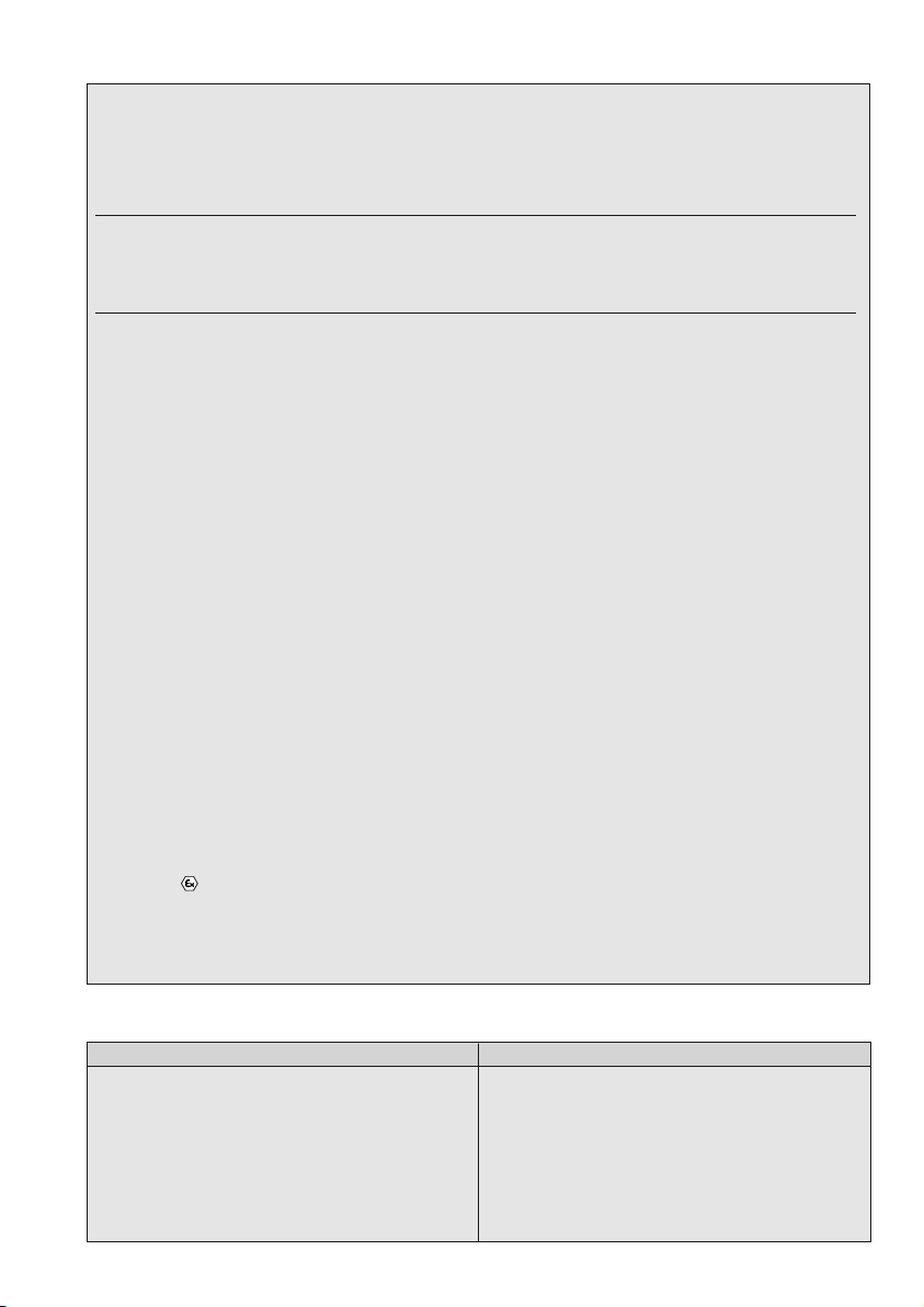
FHF PROTexline mHP 11 User manual

Signalhupe / Signalling hooter
mHP 11 / mHP 12
FHF BA 6981-02 03/16
mHP 12 ohne Schalltrichter / without trumpet
• Die Signalhupe ist als ortsfestes Gerät der
Gerätegruppe II, Kategorie 2 für den Einsatz
in explosionsfähigen Bereichen ausgeführt.
• Die Zündschutzart II 2 G Ex e mb IIC T5 Gb /
II 2 G Ex e mb IIC T Gb erlaubt den Einsatz
der Hupe in den Zonen 1 und 2.
• Die Signalhupe erzeugt einen Schallpegel von
ca. 108 dB (A) in 1 m Abstand.
• The signalling hooter is a group II, category 2
stationary device, developed for use in areas
with explosive atmospheres.
• The II 2 G Ex e mb IIC T5 Gb / II 2 G Ex e mb IIC
T Gb explosion class enables the use of the
hooter in hazardous areas of zones 1 and 2.
• The hooter produces a sound pressure level
of approx. 108 dB(A) at 1 m distance.
1
mHP 11 mit Schalltrichter / with trumpet Maßbild / Dimensions mHP 11
Abmessungen / Dimensions
mm]
M20 x 1,5
Maßbild / Dimensions mHP 12
Abmessungen / Dimensions
mm]
M20 x 1,5
Wir erklären hiermit, dass sich dieses Produkt in Überein-
stimmung mit den grundlegenden Sicherheits- und
Gesundheitsanforderungen
der ATEX-Richtlinie 2014/34/EU, der EMV-Richtlinie 2014/30/EU,
der Niederspannungsrichtlinie 2014/35/EU und
der RoHS-Richtlinie 2011/65/EU befindet.
Die entsprechenden Normen, technischen Regeln und
Spezifikationen entnehmen Sie bitte der beigefügten
Konformitätserklärung und den Konformitätserklärungen
auf unserer Website.
CE-Zeichen
We hereby declare this product is in compliance with the
Essential Health and Safety Requirements of
ATEX Directive 2014/34/EU,
EMC Directive 2014/30/EU,
Low Voltage Directive 2014/35/EU and
RoHS Directive 2011/65/EU.
The appropriate standards, technical regulations und
specifications you can take from the attached
conformity declaration and the conformity declarations
on our Website.
CE symbol

2
Montage und Anschluss / Mounting und Connection
Einstellen der Hupe
Jede Hupe wird im Werk eingestellt. Sollte sich der Ton
nach einer bestimmten Betriebszeit verstellen, so kann
das Einstellen des Stößels im Gerät durch eine
Fachkraft wie folgt durchgeführt werden:
• die Einstellarbeiten dürfen nur außer halb des explo -
sionsgefährdeten Bereiches ausgeführt werden;
• Gerät öffnen, ACHTUNG
Spannungsführende Teile;
• Nennspannung anlegen;
Aufbau
Lotrecht, Schallöffnung nach unten.
Instandhaltung
Die Signalhupe enthält keine zu wartenden Teile.
Inbetriebnahme
Nach Anschluss an die Versorgungs leitung ist die Hupe
betriebsbereit.
Wartung und Pflege
Reinigungsarbeiten dürfen nur mit einem feuchten Tuch
durchgeführt werden. Die Vorgaben der EN60079-17
hinsichtlich der regelmäßigen Überprüfung des Explo -
sionsschutzes sind einzuhalten
Recycling
Die Komplettentsorgung der Geräte erfolgt über den
Elektronikabfall. Bei Demontage des Gerätes sind die
Komponenten Kunststoff, Me talle und Elektronik separat
zu entsorgen.
Hinweis
Bei Überhitzung durch zu langen Dauerbetrieb der AC-
Ausführungen, wird die Hupe durch einen Temperatur-
schalter abgeschaltet. Nach dem Abkühlen schaltet sie
automatisch wieder ein. Bei den DC-Ausführungen wird
das Energieverhalten elektronisch geregelt.
Adjusting the hooter
Each signalling hooter is adjusted in the works. Should
the sound alter after a certain number of operating
hours, a qualified person can ad just the tappet in the
device as follows:
• The adjustment work must be carried through outside
the area endangered by the explosive atmosphere.
• Open the device, WARNING
Live parts
• Apply rated voltage
Design
Vertical, trumpet opening downward.
Service
The signalling hooter contains no serviceable parts.
Placing into operation
After having been connected to the mains, the signal-
ling hooter is operational.
Care and maintenance
Clean the device with a moist cloth only.
The requirements of EN60079-17 regarding the
regular control of the explosion protection must be
observed.
Recycling
The device may be completely recycled as electronic
waste. When the device is disassembled, plastics,
metals and electronics are to be disposed of
separately.
Note
In case of overheating caused by too long continuous
operation of the AC versions, a temperature switch
turns the hooter off. Having cooled off, it automatically
turns on again. As for the DC versions, the energy-
related behaviour is electronically controlled.
• Set item 1 to approx.
35 mm.
• Release item 3.
• Turn item 2, until sound is
loud and clear (no rattling)
• Tighten item 3 again.
• Close device.
• For your own safety, please
note: Due to the high sound
volume du ring the adjust-
ment, carry ear protection!
• Pos. 1 auf Abstand
ca. 35 mm einstellen;
• Pos. 3 lösen;
• Pos. 2 drehen, bis der Ton
laut und klar ist (kein Klappern);
• Pos. 3 wieder anziehen;
• Gerät schließen;
• Hinweis für Ihre Sicherheit:
wegen der hohen Lautstärke
bei den Ein stellarbeiten
Gehörschutz tragen!
3
Anschlussdaten
Anschlussquerschnitt bis 2,5 mm2
Leitungseinführung M20 x 1,5
Zündschutzart II 2 G Ex e mb IIC T5 Gb
Ex e mb II T5
Betriebsumgebungstemperatur DC-Ausführungen AC-Ausführungen
-20°C bis +60°C -20°C bis +50°C
Zündschutzart II 2 G Ex e mb IIC T4 Gb
Ex e mb II T4
Betriebsumgebungstemperatur DC- und AC-Ausführungen
-20°C bis +70°C
Lagertemperatur -40°C bis +80°C
Betriebsgebrauchslage Schallmündung nach unten
Betriebsart Einschaltdauer ED 75%
Gehäuseschutzart IP54
Schutzklasse II
Überspannungskategorie II
Lautstärke ca. 108 dB(A), 1m
Material PC, schwarz
Kennzeichnung auf dem Typenschild
FHF Funke+Huster Fernsig GmbH D-45478 Mülheim
PTB 07 ATEX 2039 X
IECEx PTB 10.0054 X
II 2 G Ex e mb IIC T5* Gb
Ex e mb II T5*
-20°C ≤ Ta ≤ +50°C* oder
II 2 G Ex e mb IIC T5* Gb
Ex e mb II T5*
-20°C ≤ Ta ≤ +60°C* oder
II 2 G Ex e mb IIC T4* Gb
Ex e mb II T4*
-20°C ≤ Ta ≤ +70°C*
Ui = *)...... IP*)
Nicht unter Spannung öffnen
CE
Art.-Nr.: ……………
F-Nr.:………………
WARNUNG!–Gefahr durch elektrostatische Entladungen – siehe Betriebsanleitung
*) je nach Ausführung
Technische Daten
Elektrische Kenngrößen
Anschlusswerte
6 VAC 50 Hz +10/-15% 3,40 A
12 VAC 50 Hz +10/-15% 1,20 A
24 VAC 50 Hz +10/-15% 0,65 A
60 VAC 50 Hz +10/-15% 0,25 A
115 VAC 50 Hz +10/-15% 0,15 A
230 VAC 50 Hz +6/-15% 0,07 A
120 VAC 60 Hz +10/-15% 0,15 A
240 VAC 60 Hz +10/-15% 0,07 A
Anschlusswerte
6 VDC +10/-15% 1,00 A
12 VDC +10/-15% 0,60 A
24 VDC +10/-15% 0,30 A
48 VDC +10/-15% 0,24 A
60 VDC +10/-15% 0,15 A
115 VDC +10/-15% 0,08 A
230 VDC +10/-15% 0,05 A

Electrical characteristics
Connection data
6 VAC 50 Hz +10/-15% 3.40 A
12 VAC 50 Hz +10/-15% 1.20 A
24 VAC 50 Hz +10/-15% 0.65 A
60 VAC 50 Hz +10/-15% 0.25 A
115 VAC 50 Hz +10/-15% 0.15 A
230 VAC 50 Hz +6/-15% 0.07 A
120 VAC 60 Hz +10/-15% 0.15 A
240 VAC 60 Hz +10/-15% 0.07 A
Connection data
6 VDC +10/-15% 1.00 A
12 VDC +10/-15% 0.60 A
24 VDC +10/-15% 0.30 A
48 VDC +10/-15% 0.24 A
60 VDC +10/-15% 0.15 A
115 VDC +10/-15% 0.08 A
230 VDC +10/-15% 0.05 A
4
Connection data
Power cable cross section up to 2.5 mm2
Cable gland M20 x 1.5
Type of protection II 2 G Ex e mb IIC T5 Gb
Ex e mb II T5
Ambient operating temperature DC versions AC versions
-20°C up to +60°C -20°C up to +50°C
Type of protection II 2 G Ex e mb IIC T4 Gb
Ex e mb II T4
Ambient operating temperature DC and AC versions
-20°C up to +70°C
Storage temperature -40°C up to +80°C
Operating utilization Sound outlet position downwards
Operating mode Duty cycle DC 75%
Housing degree of protection IP54
Insulation class II
Overvoltage category II
Sound pressure ca. 108 dB(A), 1m
Material PC, black
Name plate identification
FHF Funke+Huster Fernsig GmbH D-45478 Mülheim
PTB 07 ATEX 2039 X
IECEx PTB 10.0054 X
II 2 G Ex e mb IIC T5* Gb
Ex e mb II T5*
-20°C ≤ Ta ≤ +50°C* or
II 2 G Ex e mb IIC T5* Gb
Ex e mb II T5*
-20°C ≤ Ta ≤ +60°C* or
II 2 G Ex e mb IIC T4* Gb
Ex e mb II T4*
-20°C ≤ Ta ≤ +70°C*
Ui = *)...... IP*)
Do not open while under power
CE
P/N: ……………
F-No.:………………
Clean with moist cloth only.
WARNING! – Potential electrostatic charging hazard – see instructions
*) acc. to version
Technical Data
5
Benutzerinformation User information
This electrical equipment is a flame-proof (explosion-proof)
device designed for use in areas in which an explosive
atmosphere will occur. As a group II, category 2 G device it is
designed for use in Zone 1 and 2. The following remarks
regarding warnings and safety are to be observed:
1. The installation and adjustment of the device must be
carried out by qualified personnel in accordance with the
prescribed installation regulations taking the specified
protection class into account.
2. This apparatus is an insulation class II device and may only
be connected to and operated on the prescribed voltage.
Please observe the information regarding polarity.
3. If the device is damaged, it may not be operated.
4. If the device is operated in commercial equipment, the
Accident Prevention Regulations of the Employer’s Liability
Insurance Association for electrical units and equipment are
to be observed.
5. The equipment may only be operated under the prescribed
ambient conditions. Unfavourable ambient conditions can
lead to damage of the device and thus present a potential
danger for the user.
Unfavourable ambient conditions could include:
• Humidity of air too high (>75% rel., condensing)
• Dust deposits
• Flammable gases, vapours,
solvents not covered by the type of protection
for the device
• Ambient temperature too high (>+70°C)
e.g. because of intensive sun light
• Ambient temperature too low (<-20°C)
6. Maintenance work may only be carried out by the manu-
facturer or by a person authorized by the manufacturer
when carrying out a renewed routine test for the device.
7. During operation of the device the temperature must not
exceed nor fall below the prescribed range of ambient
temperatures. Prevent unallowed radiation energy and
convection in the vicinity of the device.
8. Warning! At the devices there is hazard of ignition by
electrostatic discharges. Charging e.g. by friction or during
cleaning has to be avoided. The assembly has to be carried
out in a way that a hazardous electrostatic charging e.g.
by pneumatic delivery will be avoided.
9. Only cable glands as prescribed by the manufacturer may
be used.
10. Take care not to damage the signalling hooters mHP 11
and mHP 12.
11. When connecting or disconnecting leads, the device and
all leads must not be under power.
12. In case of factory fitted cable glands the attached operating
instructions have to be considered.
Should these points not be observed, the explosion protection
of the device cannot be guaranteed. The device then presents
a potential source of danger for the life of the user and can
cause the ignition of an explosive atmosphere. The manufacturer
cannot be made liable for incorrect connection.
Bei diesem Betriebsmittel handelt es sich um ein explosions-
geschütztes Gerät für den Betrieb in einem Bereich, in dem
damit zu rechnen ist, dass explosionsfähige Gas atmosphäre
auftritt. Als ein Gerät der Gruppe II, Kategorie 2 G ist es in der
Zone 1 und 2 verwendbar. Nachstehende Warn- und Sicher-
heitshinweise sind be son ders zu beachten.
1. Der Anschluss und die Installation hat unter Beachtung der
Zündschutzart gemäß den vorgeschriebenen Errichtervor -
schriften von einem unterwiesenen Fachmann zu erfolgen.
2. Dieses Gerät ist in der Schutzklasse II aufgebaut und darf
nur an der vorgeschriebenen Spannung angeschlossen und
betrieben werden. Polaritätsangaben sind zu beachten.
3. Im beschädigten Zustand darf das Gerät nicht betrieben
werden.
4. Bei Betrieb in gewerblichen Einrichtungen sind die Unfall-
verhütungsvorschriften der Berufsgenossenschaften für
elektrische Anlagen und Betriebsmittel zu beachten.
5. Das Betriebsmittel darf nur unter den angegebenen
Umgebungsbedingungen betrieben werden. Widrige
Umgebungsbedingungen können zur Beschädigung des
Gerätes führen und damit zu einer evtl. Gefahr für das
Leben des Benutzers.
Solche widrigen Umgebungsbedingungen können sein:
• zu hohe Luftfeuchtigkeit (>75% rel., kondensierend)
• Staubablagerungen
• brennbare Gase, Dämpfe, Lösungsmittel, die nicht durch
die Zündschutzart des Gerätes abgedeckt sind.
• zu hohe Umgebungstemperatur (>+70°C) z.B. durch
intensive Sonneneinstrahlung
• zu niedrige Umgebungstemperatur (<-20°C)
6. Instandsetzungsarbeiten dürfen nur vom Hersteller oder
von einer vom Hersteller beauftragten Person mit erneuter
Stückprüfung durchgeführt werden.
7. Der für das Gerät angegebene Umgebungstemperaturbe-
reich darf während des Betriebes weder unter- noch über-
schritten werden. Unzulässige Strahlungsenergie und
Konvektion in der Geräteumgebung verhindern.
8. Warnung! An den Geräten besteht die Gefahr der Zündung
durch elektrostatische Entladungen. Aufladungen z.B.
durch Reibung oder während der Reinigung sind zu ver-
meiden. Die Montage muss so erfolgen, dass eine gefähr-
liche elektrostatische Aufladung z.B. durch pneumatische
Förderströme verhindert wird.
9. Es dürfen nur die vom Hersteller vorgeschriebenen
Leitungseinführungen verwendet werden.
10. Die Hupen mHP 11 und mHP 12 sind vor mechanischen
Beschädigungen zu schützen.
11. Beim Anschluss oder Abklemmen von Leitungen muss das
Gerät und die Leitung spannungsfrei geschaltet sein.
12. Bei den werkseitig bestückten KLE ist die beigefügte
Betriebsanleitung zu beachten.
Bei Nichtbeachtung der vorgenannten Punkte ist der
Explosionsschutz des Gerätes nicht mehr gegeben. Das Gerät
stellt dann eine Gefahr für das Leben des Betreibers dar und
kann die Zündung einer explosionsfähigen Atmosphäre verur-
sachen. Für den richtigen Anschluss übernimmt der Hersteller
keine Haftung.

Änderungen und Irrtum vorbehalten
Subject to alterations or errors
FHF Funke + Huster Fernsig GmbH
Gewerbeallee 15-19 · D-45478 Mülheim an der Ruhr · Web:
www.fhf.de
Phone +49 - 208-8268-0 · Fax +49 - 208-8268-286 ·
Mail: info@fhf.de
Orders: fhf-orders@eaton.com · Requests: fhf-sales@eaton.com
Support: fhf-supp[email protected]om
This manual suits for next models
2
Table of contents
Other FHF Security System manuals


