FIAL 2316 User manual

MODEL 2314/2316
SNMP ALARM ENCODER
FIAL INCORPORATED
710 CENTER STREET
OREGON CITY, OR 97045
503.607.1940
WWW.FIAL.COM
DOCUMENT NUMBER 2314/2316-042315
COPYRIGHT © 2015 BY FIAL INCORPORATED

NOTICE OF FCC COMPLIANCE
NOTE
This equipment has been tested and found to comply with the limits for a Class A
digital device pursuant to Part 15 of FCC Rules. These limits are designed to
provide reasonable protection against harmful interference when this equipment is
operated in a commercial environment. This equipment generates, uses, and can
radiate radio frequency energy and, if not installed and used in accordance with the
instruction manual, may cause harmful interference to radio communication.
Operation of this equipment in a residential area is likely to cause harmful
interference, in which case the user will be required to correct the interference at
his/her own expense.

Model 2314/2316 SNMP Alarm Encoder
Fial Incorporated 2314/2316-042315 i
TableofContents
1INTRODUCTION..................................................................................................................................1
2DESCRIPTION.....................................................................................................................................2
FRONT PANEL LEDS:..............................................................................................................................2
ALARM INPUTS:.......................................................................................................................................2
Alarm point vs. Status point:.............................................................................................................2
Delayed activation:.............................................................................................................................2
CONTROL OUTPUTS:..............................................................................................................................2
ANALOG INPUTS:....................................................................................................................................3
3INSTALLATION....................................................................................................................................4
STATION GROUND CONNECTION (STA. GND) CAUTION....................................................................4
ALARM LED OPTOISOLATOR POWER..................................................................................................4
AC POWER RECOMMENDATION (AC POWER SUPPLY NOT INCLUDED).........................................5
EXTERNAL I/O CONNECTOR.............................................................................................................5
4CONFIGURING THE SNMP ALARM ENCODER.................................................................................7
INITIAL NETWORK CONFIGURATION SETTINGS WITH THE CRAFT SERIAL PORT.........................7
COMPLETE CONFIGURATION USING A WEB BROWSER.................................................................12
The Alarm Inputs Page.....................................................................................................................15
The Analog Inputs Page...................................................................................................................19
The Boolean Alarms Page................................................................................................................21
The Event Log Page..........................................................................................................................23
The IP Settings Page ........................................................................................................................24
The RTC Time/Date Page..................................................................................................................27
The SNMP Notifications Page..........................................................................................................29
Web Browser interface - Logins and Passwords...........................................................................32
The Config File..................................................................................................................................34
Firmware Upgrade ............................................................................................................................35
Undo All Changes.............................................................................................................................36
Save & Reboot...................................................................................................................................36
5CONFIGURING THE SNMP MASTER...............................................................................................37
SNMP NOTIFICATIONS:........................................................................................................................37
SNMP CONTROLS:................................................................................................................................37
6NOTES ...............................................................................................................................................40
WEB PAGE PROVISIONING CAUTION.................................................................................................40
REMOTE WEB OR TELNET PROVISIONING CAUTION ......................................................................40
HOSTNAME............................................................................................................................................40
IP ADDRESS RESTRICTIONS...............................................................................................................41
LOGIN & PASSWORD............................................................................................................................42
SAVE & REBOOT...................................................................................................................................42
WEB & UNIX COMPATIBLE BROWSERS.............................................................................................42

Model 2314/2316 SNMP Alarm Encoder
ii 2314/2316-042315 Fial Incorporated
REPLACING THE RTC BATTERY..........................................................................................................43
TRIVIAL FILE TRANSFER PROTOCOL (FIRMWARE UPGRADE).......................................................43
7CREATING BOOLEAN ALARM POINTS AND EXPRESSIONS ........................................................45
8I/O CONNECTOR PIN DESIGNATIONS............................................................................................52
9ETHERNET CONNECTOR (RJ-45 JACK)..........................................................................................53
102314/2316 REMOTE ENCODER SPECIFICATIONS.........................................................................55
DC POWER SPECIFICATIONS..............................................................................................................56

Model 2314/2316 SNMP Alarm Encoder
Fial Incorporated 2314/2316-042315 iii
TABLE OF FIGURES
Figure 1. Model 2314 Front Panel................................................................................................................1
Figure 2. Model 2316 Front Panel................................................................................................................1
Figure 3 . Positive Ground Jumper Power Input Example............................................................................4
Figure 4. Battery Polarity Selection For Optoisolators..................................................................................5
Figure 5. Craft Port Login Window................................................................................................................8
Figure 6. Main Menu.....................................................................................................................................8
Figure 7. Setting IP Address Via HyperTerminal..........................................................................................9
Figure 8. Set Netmask via Craft Screens......................................................................................................9
Figure 9. Set Gateway Via HyperTerminal.................................................................................................10
Figure 10. Set Login & Password via Craft Screens...................................................................................10
Figure 11. Initial Welcome Page.................................................................................................................13
Figure 12. Enter User Name & Password Via The Web.............................................................................13
Figure 13. Event Log Page.........................................................................................................................14
Figure 14. Alarm Inputs Page Via The Web ...............................................................................................15
Figure 15. Control Outputs Page Via The Web...........................................................................................17
Figure 16. Analog Inputs Page Via The Web..............................................................................................19
Figure 17. Boolean Alarms Page Via The Web..........................................................................................22
Figure 18. Event Log Page Via The Web ...................................................................................................23
Figure 19. The IP Settings Page.................................................................................................................24
Figure 20. RTC Time/Date Page Via The Web...........................................................................................27
Figure 21. SNMP Notifications Page Via The Web.....................................................................................29
Figure 22. Set Login & Password Via The Web..........................................................................................33
Figure 23. Configuration Text Screen.........................................................................................................34
Figure 24. Firmware Upgrade Via TFTP.....................................................................................................35
Figure 25. Undo All Changes Screen.........................................................................................................36
Figure 26. Save & Reboot Screen..............................................................................................................36
Figure 27. Browse encControlPointTable...................................................................................................38
Figure 28. Setting Spinlock Variable...........................................................................................................38
Figure 29. Set Request with Spinlock and Control Point State Variables...................................................39
Figure 30. TFTP Server Window................................................................................................................44
Figure 31. TFTP Server Directory Window.................................................................................................44
Figure 32. Boolean Alarms Screen.............................................................................................................45
Figure 33. First point in Boolean Expression..............................................................................................47
Figure 34. Partial Simple AND Expression.................................................................................................47
Figure 35. Completed Simple AND Expression..........................................................................................48
Figure 36. Second Boolean Example.........................................................................................................49
Figure 37. Completed Unasserted Condition Expression...........................................................................49
Figure 38. Simple OR’d Expression............................................................................................................50
Figure 39. Creating a Complex Boolean expression...................................................................................51

Model 2314/2316 SNMP Alarm Encoder
iv 2314/2316-042315 Fial Incorporated
TABLE OF TABLES
Table 1. Analog Input Attenuation Versus Frequency...................................................................................3
Table 2. Notification/Trap and Inform Request Settings.............................................................................31
Table 3. Login Names and Passwords.......................................................................................................32
Table 4. Table of Netmasks and Addresses...............................................................................................41
Table 5. 2314/2316 I/O Connector Pin Assignment....................................................................................52
Table 6. Ethernet Connector Pin Assignments...........................................................................................53
Table 7. Straight-Through Ethernet Cable Wiring (T-568B Color Code).....................................................53
Table 8. Cross-Over Ethernet Cable Wiring - opposite end........................................................................54

Model 2314/2316 SNMP Alarm Encoder
Fial Incorporated 2314/2316-042315 1
1 Introduction
The 2314 and 2316 SNMP Alarm Encoders are remote devices for use with SNMP network managers.
The 2314 encodes 8input alarm points. The 2316 encodes 16 input alarm points. Both units encode 16
Boolean (composite) alarm points, 8 analog input voltages and include 4 Form-C control relay outputs
(control points). The Boolean alarm points are created by entering Boolean expressions that combine the
true/false state of any alarm point, status point, control point or analog point using the AND, OR, XOR and
NOT operators. A 10/100BaseT LAN port connects to an IP network for access by any SNMP V2
compatible manager. With the exception of the number of alarm inputs, both the 2314 and 2316 SNMP
Alarm Encoders are identical in operation.
The 2314/2316 SNMP Alarm Encoder is provisioned using a Web browser. An RS232 craft interface can
be used to set IP Address, Netmask and Gateway. A Web browser can also be used to view the current
state of all alarms, the current values of analog inputs and to activate or deactivate any control relays. Web
access login is secured by an authorized user name and password. There are three levels of
authorizations provided: one for viewing only, one for viewing and issuing controls, and one for
administrative configuration functions. A secure HTTPS (port 443) web connection is also available if
higher security is required.
Both the 2314 and the 2316 also include a Form-C summary-alarm relay. The summary relay operates
(closes) for any critical (CR), major (MJ) or minor (MN) alarm. A status (ST) alarm does not cause the
summary relay to close.
The front panel contains LED indicators for power, summary alarm, LAN connection status (link, activity),
and individual alarm (or control point) states. The 2314 displays a single row of 8alarm input LEDs, while
the 2316 displays 16 alarm input LEDs, in 2 rows of 8 LEDs each. All connections are on the front panel.
The rear panel is blank.
Figure 1. Model 2314 Front Panel
Figure 2. Model 2316 Front Panel

Model 2314/2316 SNMP Alarm Encoder
2 2314/2316-042315 Fial Incorporated
2 Description
Front Panel LEDs:
The Model 2314/2316 SNMP Alarm Encoder includes front panel LED indicators for unit power
(PWR), summary point state (SUM ALM), and LAN connection and activity status (LINK & ACT).
The 2314 includes 8 individual front panel alarm point status LEDs, while the 2316 includes 16
individual alarm point status LEDs (2 rows of 8 alarms each). These red LEDs display the current
states of the unit’s alarm points. LEDs are illuminated for asserted (ON) alarms (or controls - see
below).
Pressing the Lamp Test button turns all front panel LEDs on (except the two LAN indicators) to test
lamp functionality. If you hold the Lamp Test button down for over 3 seconds, then the first four top
row LEDs (1 through 4) will show the current state of the 4 control relays. Releasing the LAMP
TEST button returns all LEDs to their normal function.
Alarm Inputs:
The alarm inputs are optically isolated. Alarm inputs can be asserted either by connecting the
input to station ground (normal input), or by removing ground from the input (inverted input). Each
alarm input can be set for a delay (up to 9999 seconds) before asserting an alarm. The external
device driving the inputs must handle a current of 2 milliamperes. The alarm inputs are scanned
every 200 milliseconds. The alarm input connector is a female 50-pin CHAMP (AMP) on the front
panel.
Alarm point vs. Status point:
Each of the alarm inputs may be configured to be an alarm point or a status point. Once
asserted, an alarm point is latched until read (polled). Status points are not latched, this
means the state of the point changes in real-time with the state of the input pin.
Delayed activation:
Each of the alarm inputs may have a delay associated with it. This is useful when you
want to ignore short, intermittent events. The delay may be set from one second up to
about 9999 seconds (2.77 hours). For example, if an input has a 10 second delay set,
then the point must be continuously asserted (uninterrupted) at the input pin for a minimum
of 10 seconds before the alarm point is considered ‘ON’ in the 2314/2316.
Control Outputs:
The 4 control outputs are provided by activation of Form-C relay contacts (normally open, common,
and normally closed contacts). The Form-C contacts allow the power-off default to be wired as
normally off or normally on. The relay output connector is a female 50-pin CHAMP mounted on the
front panel. The contacts are rated for 1 Amp up to 48 volts DC, 0.6 Amps at 110 volts DC, and
0.6 Amps at 125 volts AC.

Model 2314/2316 SNMP Alarm Encoder
Fial Incorporated 2314/2316-042315 3
The default mode of operation for the control point is ON/OFF. An SNMP 'set' command of ON will
close the relay, and a set OFF command will open the relay. The configuration program also
allows you to make any of the outputs act in a momentary fashion. If momentary is selected, then
the relay is operated for 200 milliseconds for ON command. OFF commands are ignored for relays
configured as momentary.
Analog Inputs:
Both the 2314 and 2316 have 8 analog (voltage measuring) inputs. Each input can measure a
voltage range of negative 90 volts to positive 90 volts.
The analog inputs are generally measured relative to a common ground. However, fixed pairs of
inputs may be set to differential input mode. A maximum of 4 differential pairs is possible. In
differential mode, the measurement is made between the two inputs of the pair, rather than
between an input and ground. For example, if input 1is set to differential mode, then input 1
becomes the positive input and input 2becomes the negative input of the pair. If input 3is set to
differential mode, then input 3becomes the positive input and input 4 becomes the negative input
of the pair, and so on. The configuration program allows you to choose either single-ended
(standard) vs. differential pair mode for analog inputs.
The input resistance for each analog input is 698k Ohms to ground.
Each analog input is RC low-pass filtered in order to reject higher frequencies. The time constant
is approximately 0.05 seconds. The attenuation versus frequency table is below.
Frequency Attenuation
DC (0 Hertz) 0x
5 Hz 1.6x
10 Hz 2.8x
20 Hz 4.1x
60 Hz 14.5x
120 Hz 29.2x
240 Hz 58.3x
1000 Hz 175x
Table 1. Analog Input Attenuation Versus Frequency
Shielded wire is recommended for connecting distant measuring points to the input connector, and
shielded pair cable is recommended for connecting differential inputs to the input connector.

Model 2314/2316 SNMP Alarm Encoder
4 2314/2316-042315 Fial Incorporated
3 Installation
This 1U unit can be installed in 24 or 48 volt stations (18 to 72 volts operation) with either positive
ground or negative ground. NOTE: Original 2314/16 units (sold prior to April 2011 serial#
1116062) were 48-volt-only units. The factory default is for Positive ground operation. The
2314/2316 SNMP Alarm Encoder is shipped with a 3-wire plug (snap-in DC power connector) with
screw terminals.
The left-most connection (Sta Gnd) is chassis ground and must be grounded to station ground
(rack ground). This ground wire is the return path to the battery for alarm inputs. For Positive
Ground stations, this wire must have a conductive path back to the battery's Positive terminal. For
Negative Ground stations, this wire must have a conductive path back to the battery's Negative
terminal. The power input is reverse-voltage protected and under/over voltage protected.
Figure 3 . Positive Ground Jumper Power Input Example
Mounting ears are supplied for flush mounting in a 19-inch rack. The mountings may be reversed
for 1.75-inch projection mounting.
STATION GROUND CONNECTION (STA. GND) CAUTION
Some telecom sites may require all station battery connections to be grounded at only one point
near the battery bank. If your installation requires an isolated station battery input, you must run
the Sta Gnd wire from the power connector at the front of the unit to a rack-ground so it gets to the
station battery ‘common’ via the station ground.
Important! Do not attempt to operate the equipment without a dedicated station ground (STA.
GND, chassis ground, rack ground) connection, as electrical damage may occur. The unit’s rack
mounting screws alone will not provide a reliable rack ground due to their anodized surfaces. This
ground is also a reference ground for the alarm inputs, and this ground is also provided on the
alarm-input connector. See the following Alarm LED Optoisolator Power section.
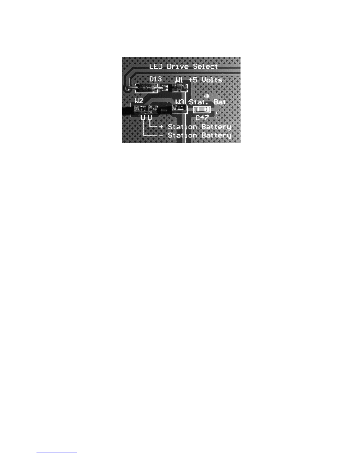
ALARM LED OPTOISOLATOR POWER
There is an internal jumper (see Figure 4) that selects the negative or positive lead of the battery
input to power the alarm input optoisolators. For POSITIVE GROUND systems (factory default)
the jumper should be in the NEGATIVE - Station Battery position. This selects the proper polarity
voltage input to power the optoisolators. For NEGATIVE GROUND systems, the jumper must be
switched to the POSITIVE + Station Battery position. If this jumper is in the wrong position, an
alarm input will not be asserted when the alarm input is connected to Station Ground.
Model 2314/2316 SNMP Alarm Encoder
Fial Incorporated 2314/2316-042315 5
Figure 4. Battery Polarity Selection For Optoisolators
AC POWER RECOMMENDATION (AC power supply not included)
For the wide range 18 to 72 VDC supply voltage 2314/2316 RTUs, if DC Station Battery is
unavailable and an AC power supply is required, the use of a 24V, 1.5 to 2.0 amp wall-mount or
desktop style switching power supply is recommended. These power supplies may be purchased
from many different sources and generally cost around $20 to $30. The power supply DC
connector (typically a barrel style plug) will need to be removed and the power supply lead wires
connected to the appropriate 2314/2316 DC power input connector terminals (provided with the
unit). Connect the power supply Positive lead to the Positive input connector terminal and the
power supply Negative lead to the Negative input connector terminal. The 2314/2316 DC power
input connector Sta. Gnd terminal needs to be connected (jumper wire) to the proper power supply
input terminal, which will depend on the ground reference used for the equipment connecting to the
2314/2316 Alarm Inputs. Make sure to follow the previous instructions regarding Station Ground
requirements on page 4.
LAN CONNECTION: The SNMP Alarm Encoder is connected to the IP network using an Ethernet
RJ45 jack and standard 10BaseT or 100BaseT wiring. The LAN port will automatically switch to
10BaseT or 100BaseT, depending on the connection type at the other end of the cable.
EXTERNAL I/O CONNECTOR
A 50-pin Champ (AMP) connector is used for alarm input, analog inputs and relay outputs.
It is best to order a pre-assembled cable assembly from a company such as Grayhill. One easy
option is to use a cable with a 50-pin AMP connectors at each end and a 66M block (punch-down
block) pre-wired to a 50-pin AMP connector. The cable end that connects to the 2314/2316
should be a male, connector. The other end should mate with the 66M block. 66M blocks can be
ordered with male or female connectors. The punch down block can be mounted on the wall, and
all the station connections brought to that block. Follow the pin assignments for the connector
detailed at the end of this document (Table 8-1).

Model 2314/2316 SNMP Alarm Encoder
6 2314/2316-042315 Fial Incorporated
RELAY OUTPUTS:
Note the pin numbers carefully. Follow the pin assignments for the connector detailed at the end of
this document (Table 5).
ANALOG INPUTS
The connector has separate pins for station ground and analog ground. These are connected
together at the 'common' measurement point on the analog board.
Single ended measurements may be connected between an analog input pin and analog ground.
For the most accurate measurements, a pair of wires should run from the device being measured
to the model 2314/2316, with the 'ground' wire connected to an analog ground pin and the active
wire connected to the analog input pin. A shielded wire is recommended for electrically noisy
environments, and a shielded pair is recommended for differential input measurements.
The analog inputs are low pass filtered. There is no attenuation for frequencies below 1 Hertz. A
60-Hertz signal is attenuated 14.5 times relative to DC. Table 1 on page 3 contains attenuation
data for other frequencies.
The main steps involved in installing a Model 2314/2316 SNMP Alarm Encoder are:
Step 1: Install the unit in a 19-inch rack and connect to station battery (verify power polarity and
station ground connections). Connect the LAN cable, and 50-pin I/O cable.
Step 2: (Factory New units) Configure the unit with the proper IP address/netmask/gateway
settings. Use either the RS-232 Craft Port or Web Browser to edit the factory default
addresses. Verify that the device replies to pings for the new settings from another site in
your network. This confirms that gateway IP address and netmask are correct. If you
cannot ping the unit, check the settings using the craft interface (9600 8N1). If the unit
responds to pings, most other problems can be resolved remotely using the web interface.
Use the Web browser interface to connect to the 2314/2316 using the new IP address and
finish configuring the rest of the 2314/2316 SNMP Alarm Encoder settings.
Step 3: It is a good idea to verify that all alarm inputs, control relay outputs and analog voltage
inputs are working properly before leaving the site. This is easily done on-site using the
web interface.
Step 4: Configure your SNMP manager for the 2314/2316 SNMP Alarm Encoder. Compile the
Fial Incorporated registry MIB (fial-registry-mib.mib) and the Fial Incorporated Encoder MIB
(fial-enc-mib.mib) into the manager. Note: Fial Inc. Encoder MIB is used for the 2311,
2314 and 2316 SNMP Encoder products. Add the Network Elements to be monitored.

Model 2314/2316 SNMP Alarm Encoder
Fial Incorporated 2314/2316-042315 7
4 Configuring the SNMP Alarm Encoder
Each SNMP Alarm Encoder must be configured prior to use. A default IP address (192.168.1.200,
netmask 255.255.255.0, gateway 192.168.1.200) is preset in each SNMP Alarm Encoder shipped from the
factory; however, you must set the actual IP address the device will use in your network. In addition, you
must configure settings that allow SNMP managers to access and control the unit, and that regulate the
sending of SNMP V2 notifications (autonomous messages or ‘traps’).
The 2314/2316 SNMP Alarm Encoder must be provisioned using a Web browser. However, a craft
interface (RS-232 (9600 8N1) is also available for initially setting IP address, netmask, gateway and
administrator name/password should you be unable to connect using a Web browser. The craft interface
screens are also accessible remotely via a telnet connection.
All 2314/2316 SNMP Alarm Encoders provisioning and configuration should be performed using a Web
browser. The Web pages also provide a configuration download /upload function. This allows one unit’s
setting to be saved and uploaded to other units. See Complete Configuration using a Web Browser on
page 12.
The web interface will not be accessible if you do not know the device's current IP settings. The physical
craft port is always accessible for changing the IP settings.
Initial Network Configuration Settings with the Craft Serial Port
The Craft (serial) port interface uses RJ45 pins 4, 5 and 8 to provide an RS-232 connection for a PC COM
port. The connections are shown in Table 8-2. The usual connection is with HyperTerminal at 9600 baud,
8-data bits, no-parity and 1-stop bit. Set Flow Control to ‘none.’ Power up the SNMP Alarm Encoder and
after about 30 seconds the login prompt will appear (see Figure 5). The configuration menu is identical for
both 2314 and 2316 encoders.
Model 2314/2316 SNMP Alarm Encoder
8 2314/2316-042315 Fial Incorporated
Figure 5. Craft Port Login Window
Log in with the proper user name and password. The factory default Administrator login name is admin
and the factory default password is remote. The Main Menu will then be displayed.
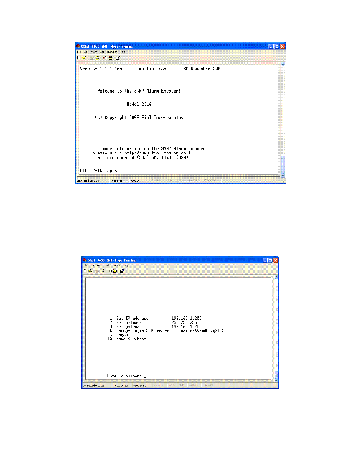
Figure 6. Main Menu

Model 2314/2316 SNMP Alarm Encoder
Fial Incorporated 2314/2316-042315 9
The Main Menu window has a list of several options for configuring the SNMP Alarm Encoder. To
configure the device, complete the following steps:
1. Set the IP Address
To set a new IP Address for your SNMP Alarm Encoder, select 1 and press Enter. The
Set IP Address window will appear.
Figure 7. Setting IPAddress Via HyperTerminal
After the prompt, enter the new IP address and press Enter.
NOTE: Do not select option 10 (Save & Reboot) until you have made any related netmask
and gateway changes and then double-checked them. Not doing this may render the
device inaccessible from the LAN (See IP Address restrictions on page 41).
2. Set the Netmask
To set the new netmask for the SNMP Alarm Encoder, select option 2 and press Enter.
The Set netmask window will appear.
Figure 8. Set Netmask via Craft Screens
After the prompt, enter the netmask and press Enter.
NOTE: Do not select option 10 (Save & Reboot) until you have made any other changes
for the device and verified them. Doing otherwise may render the device inaccessible from
the LAN. (See IP Address restrictions on page 41).
3. Set the Gateway
To set the new gateway for the SNMP Alarm Encoder, select option 3 and press Enter.
The Set Gateway window will appear.

Model 2314/2316 SNMP Alarm Encoder
10 2314/2316-042315 Fial Incorporated
Figure 9. Set Gateway Via HyperTerminal
After the prompt, enter the Gateway address and press Enter. The gateway address
should be an IP address of the IP router port to which the 2314/2316 is connected. The
router should provide a network connection that reaches the SNMP manager(s).
NOTE: Do not select option 10 (Save & Reboot) until you have made any other changes
for the device and verified them. Doing otherwise may render the device inaccessible from
the LAN. (See IP Address restrictions on page 41).
4. Change Login & Password
Each SNMP Alarm Encoder has a default login (admin) and password (remote)
programmed at the factory. Both the login name and password are case sensitive. Any
user with the administrator login and password will have access to the Craft port of the
device and web page configurations. For security purposes, it is recommended that the
login names and passwords for each device be changed during the initial configuration.
If you forget the new login/password or are unable to log in to the device, the administrator
login and password can be reset to the factory default by holding down the lamp test
button while the device is restarted (reset). You must hold down the button for
approximately 40 seconds until the power-on lamp test is done. No other provisioning
(such as IP address) will be affected.
To change the administrator login name and password for an SNMP Alarm Encoder, select
option 4 and press Enter. The Set Login & Password window will appear.
Figure 10. Set Login & Password via Craft Screens
To change the login and password, follow the prompts: enter the new login, enter the new
password, and then re-enter the new password. Remember that both the login and
password are case sensitive. A-Z, a-z, 0-9, and hyphen are the only characters allowed
for the login. The password can be any combination of charters, numbers and special
characters. Passwords should be longer than 8 characters in length. For more
information, refer to Login & Password in the Notes section on page 42.

Model 2314/2316 SNMP Alarm Encoder
Fial Incorporated 2314/2316-042315 11
5. Logout
To log out of the SNMP Alarm Encoder configuration session, type 5 and press Enter. If
you are using HyperTerminal you will be logged out of the device and presented with the
login screen again. If you connected using telnet, Logout will close your telnet connection.
NOTE: If you have changed settings, then select 10 (Save & Reboot) before logging out.
6. Save & Reboot
After all changes have been made for the SNMP Alarm Encoder, choose option 10 (Save
& Reboot). This will save your changes, and the device will restart with the new settings.
If you do not choose Save & Reboot, any changes made in this login session will not take
effect. The reboot process takes 30 to 40 seconds to complete.

Model 2314/2316 SNMP Alarm Encoder
12 2314/2316-042315 Fial Incorporated
Complete Configuration using a Web Browser
To provision a new 2314/2316 SNMP Alarm Encoder using a Web browser, you must know the IP address
of the device and be able to ping the unit. You can connect the encoder directly to a computer with an
Ethernet Crossover cable (see Cross-Over Ethernet Cable Wiring - opposite end on page 54), or connect
both your computer and the SNMP Alarm Encoder to a hub or a switch with a standard Ethernet cable.
The computer should have Microsoft Internet Explorer Web browser 6.0 or later, or Netscape 7.1 or later or
Firefox as a default Web browser. For Netscape 7.1, verify that Enable JavaScript for Navigator is
“checked” in the Edit/Preferences/Advanced/Scripts & Plugins/Verify device. Most Opera and Mozilla
browser releases will also work.
If this is a factory new 2314/2316 and you are ONLY connecting the LAN port on your computer and on the
encoder together, set your computer to an IP address in the range of 192.168.1.2 to 192.168.1.253,
netmask to 255.255.255.0. Set your gateway address to match the IP address of your computer. (Do NOT
use IP address 192.168.1.200, since this is the SNMP Alarm Encoder factory default address).
For example, set your computer IP address to 192.168.1.10, your netmask to 255.255.255.0, and your
gateway to 192.168.1.10. Open your Web browser program.
If this is the initial configuration of the SNMP Alarm Encoder, enter http://192.168.1.200 into the browser’s
URL/address bar and press Enter. The SNMP Alarm Encoder Welcome page should appear, (see Figure
11).
If the Model 2314/2316 IP address has already been changed, you will need to know its current IP address
in order to connect using a Web browser. Enter the current IP address of the encoder in the browser’s
URL/address bar. If you do not know the unit’s current IP address, you may find this out (or change it)
using the serial Craft port interface.
Warning: When you change the IP address, gateway and netmask using the Web browser or telnet
interface, you will probably lose your IP connectivity with the device. This will happen when you choose
Save & Reboot. If the device is local, you may then need to change your computer IP settings to access
the 2314/2316 SNMP Alarm Encoder's web server. You normally do not want to change the IP
address, netmask or gateway if the device is remote from you!

Model 2314/2316 SNMP Alarm Encoder
Fial Incorporated 2314/2316-042315 13
Figure 11. Initial Welcome Page
The left side of the Welcome page has links to other pages, such as Alarm Inputs, Control Outputs,
Analog Inputs, Boolean Alarms and Event Log. To view the Event Log page or make any changes to
the provisioning, you must first select a menu item on the left side to begin a login dialog.
To access any of the main Welcome page options, click on the hot links in the left pane. Click on a link on
the left, for example the Event Log link, and the Enter Network Password login screen will appear (see
Figure 12). You must log in with a valid user name and password to access any of the links.
Figure 12. Enter User Name & Password Via The Web
If this is the first time the device has been provisioned, enter the factory set administrative user name
(admin) and password (remote) in the fields and click OK. Both entries are all lowercase. Otherwise,
enter the correct user name and password for administrative privileges in the appropriate fields and then
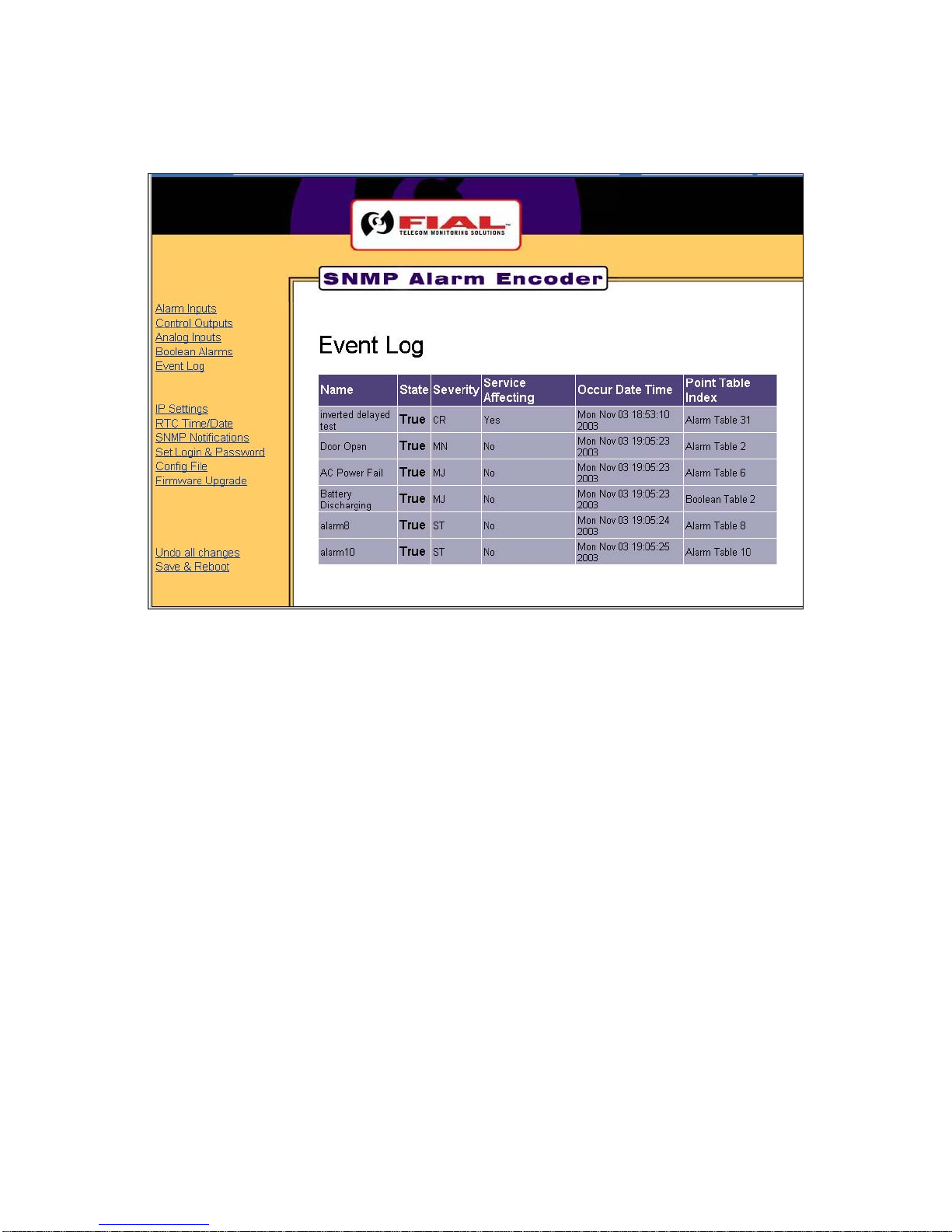
click OK. This opens up the initially selected link page, such as the Event Log page (see Figure 13).
Model 2314/2316 SNMP Alarm Encoder
14 2314/2316-042315 Fial Incorporated
Figure 13. Event Log Page
Now that you have logged in with administrative permissions, a new set of links have been added to all of
the pages. They are IP Settings, RTC Time/Date, SNMP Notifications, Set Login & Password, Config
File, Firmware Upgrade, Undo all changes and Save & Reboot. For more login related issues, refer to
Login & Password in section 6 - Notes.
This manual suits for next models
1
Table of contents
Other FIAL Media Converter manuals


