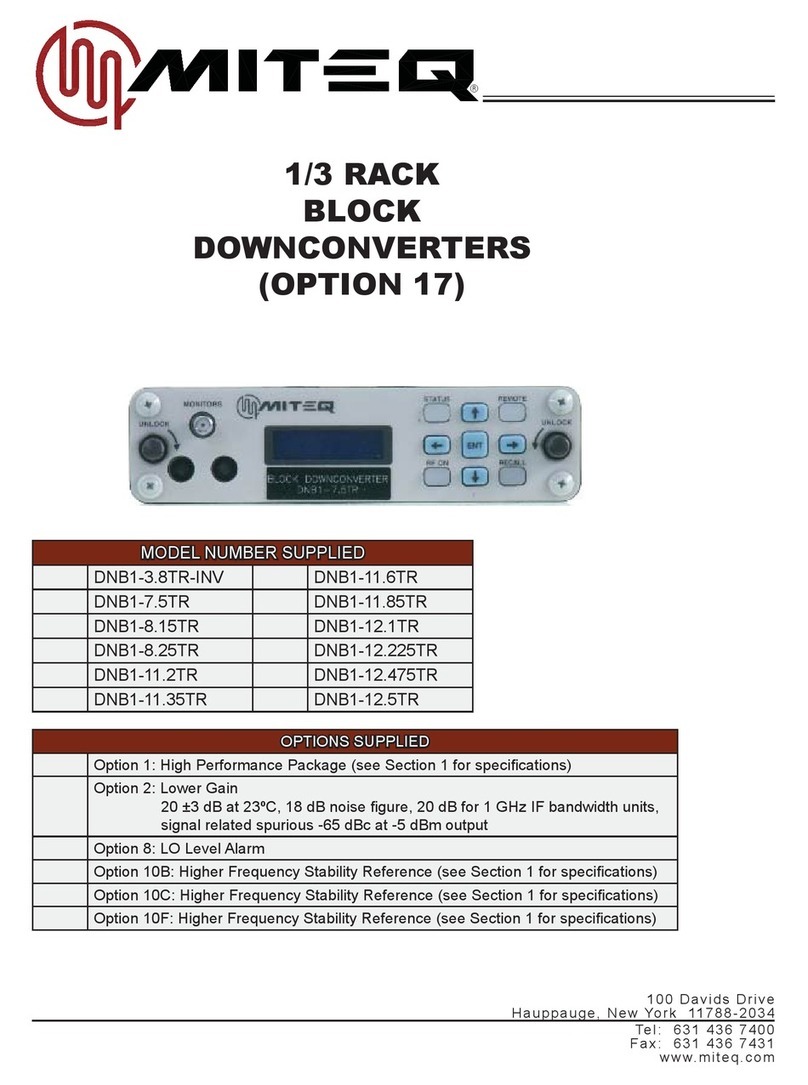
Miteq 9800 Series User manual

MODEL NUMBER SUPPLIED
UPCONVERTER
STANDARD FREQUENCY REVERSE FREQUENCY
U-9848-1-1K U-9848-4-1K U-9801R-1-1K
U-9848-5-1K U-9848-6-1K U-9802R-2-1K
U-9853-2-1K U-9853-6-1K U-9805R-1K
U-9854-1K U-9855-2-1K U-9808R-6-1K
U-9856-6-1K U-9856-7-1K
U-9857-2-1K
DOWNCONVERTER
STANDARD FREQUENCY REVERSE FREQUENCY
D-9800-3-1K D-9802-2-1K D-9853R-2-1K
D-9800-6-1K D-9805-1K D-9853R-6-1K
D-9800-7-1K D-9808-6-1K D-9854R-1K
D-9800-8-1K D-9855R-2-1K
D-9801-1-1K D-9856R-6-1K
D-9856R-7-1K
D-9857R-2-1K
*OPTIONS 1, 4, 5, 8, 10B, 10C, 10E, 10F, 14, 15, 16C, 17C, 18-4, 18-8, 20, 31A THRU 31D,
TNCIF, NRF, TNCRF LISTED ON THE FOLLOWING PAGE.
100 Davids Drive
Hauppauge, New York 11788-2034
Tel: 631 436 7400
Fax: 631 436 7431
www.miteq.com
®
9800 SERIES
FREQUENCY
CONVERTERS

OPTIONS SUPPLIED
OPTIONS SUPPLIED
Option 1: 45 dB level control
Option 4: 140 MHz IF Frequency
Option 5: Group delay equalization
1.0 ns p-p maximum/70 ±18 MHz IF output
2.0 ns p-p maximum/140 ±36 MHz IF output
Option 8: LO level detect
Option 10B: Higher Frequency Stability Reference (see Section 1 for specifications)
Option 10C: Highest Frequency Stability Reference (see Section 1 for specifications)
Option 10E: Analog Reference Phase Lock - External 5 or 10 MHz at +4 ±3 dBm.
If external reference is below +1 dBm nominal, the converter will automatically lock to the internal
reference. Reference oscillator acts as an analog phase lock with a 0.1 Hz nominal loop bandwidth.
Typical loop suppression of the external reference is as follows: 28 dB at 1 Hz offset; 65 dB at Hz
offset and 100 dB at 100 Hz offset
Option 10F: Highest Frequency Stability with Analog Reference Phase Lock
Option 14: Front panel selectable 50/75 ohms IF impedance
Option 15: 50 Ohm IF Impedance
Option 16C: +55-61 dB gain (downconverter only)
Option 17C: RS232 Remote Interface
Option 18-4: Four IF outputs (downconverter only; not compatible with NSUN or Option 14)
Output 1 dB compression point: +10 dBm, Intermodulation distortion at 0 dBm output: 40 dBc
minimum (+20 dBm IP3)
Option 18-8: Eight IF outputs (downconverter only; not compatible with NSUN or Option 14)
Output 1 dB compression point: +10 dBm, Intermodulation distortion at 0 dBm output: 40 dBc
minimum (+20 dBm IP3)
Option 20: Selectable 70/140 MHz IF frequencies.
One IF connector provided at rear panel (BNC female). Selection of IF frequency is available from
the front panel and over the remote bus
Option TNCIF: Type TNC female IF connector and IF monitor
Option NRF: Type N female RF connector (Note: Monitor remains SMA female)
RF return loss: 18 dB, 9-15 GHz, not available above 15 GHz
Option TNCRF: Type TNC female RF connector (Note: Monitor remains SMA female)
RF return loss: 18 dB, 9-15 GHz, not available above 15 GHz
Option: 45 dB minimum gain
Option 31A: Ultra-low phase noise (See Phase Noise Specifications chart). Option 10E (analog
reference phase lock) supplied as standard and an internal reference U-link is provided (an external
10 MHz reference may be applied to the U-link). Higher frequency stability available, for details see
Option 10F.
Option 31B: Ultra-low phase noise (See Phase Noise Specifications chart). Option 10F (analog
reference phase lock) supplied as standard and an internal reference U-link is provided (an external
10 MHz reference may be applied to the U-link).
Option 31C*: 5 MHz reference only (no internal provided) at +4 ±3 dBm. For ultra-low phase noise
reference (no reference suppression) or direct reference multiplication inside 100 kHz. (See below
for formula for calculation.)
Option 31D*: 10 MHz reference only (no internal provided) at +4 ±3 dBm. For ultra-low phase noise
reference (no reference suppression) or direct reference multiplication inside 100 kHz. (See below
for formula for calculation.)
*Formula for calculation of external reference only (Option 31C or 31D): External reference phase noise required to
meet the ultra phase noise system characteristics:
(U-20log(M) -3) dBc/Hz. Where U is the ultra phase noise characteristic at a specific frequency offset for a
specific model and M is the multiplication factor of the reference frequency (5 or 10 MHz) divided into the
operational RF frequency (fo) of the model selected: M = Fo (MHz)/10 (MHz) or Fo (MHz)/5 (MHz).
9800 Series Frequency Converters
9800series, Rev.M, 2/5/2013
®

Contents | iii
9800 Series Frequency Converters
9800series, Rev.M, 2/5/2013
®
DOCUMENTATION REVISIONS
The purpose of this section is to chronicle any and all changes made in this manual, in regards to both technical
information concerning this piece of equipment, and the actual format/function of this document.
11/7/07: INITIAL RELEASE
5/20/08: REV.A TO REV.B
PG.1 - IN FEATURES, CHANGED TWO MONITOR AND CONTROL PORTS TO THREE MONITOR AND
CONTROL PORTS
PG.1 - ADDED NEW REAR PANEL PHOTO
PG.4 - ADDED +55-61 dB AT 23°C (OPTION 16C), -65 dBm MAXIMUM (OPTION 16C), AND SLOPE ADJUST
ROW
PG.11 - ADDED ETHERNET INTERFACE TO MENU KEY LIST
PG.16&17 - REMOVED (SERIAL BUSES ONLY) FROM BAUD RATE AND PARITY HEADINGS
PG.16 - ADDED FIGURE 3-8a
PG.17 - REMOVED SERVICE REQUEST (IEEE-488 ONLY) SECTION AND FIGURE 3-9
MOVED AUXILIARY CONTROL INTERFACE OPERATION MENU TO PAGE 17 AND RENUMBERED ALL
FIGURES THROUGHOUT THE REST OF SECTION 3.
PG.18 - CREATED NEW ETHERNET CONTROL INTERFACE SECTION
PG.22 - REMOVED IEEE-488 MESSAGE PROTOCOL AND IEEE-488 MESSAGE FORMAT SECTIONS
PG.50 - BLOCK 175990 REV.A TO REV.B
PG.52 - BLOCK 165223 REPLACED BY BLOCK 180070
PG.56 - CONTROL BOARD P/N CHANGED FROM 152929 TO 175022
PG.59&60 - COMPLETELY RE-WROTE INSTALLING A NEW CONTROL BOARD/FIRMWARE KIT SECTION
6/30/08: REV.B TO REV.C
PG.4 - ADDED 2.92 mm TO RF AND N/A to RF MONITOR IN PHYSICAL
PG.5 - REVISED SIGNAL MONITOR IN INPUT AND OUTPUT CHARACTERISTICS FOR EXCEPTIONS
11/21/08: REV.C TO REV.D
COVER - REMOVED MODEL NUMBERS U-9858-3-1K, U-9813R-4-1K, D-9813-4-1K AND D-9858R-3-1K
PG.2 - REMOVED MODEL NUMBERS D-9813-4-1K AND D-9858R-3-1K
PG.3 - REMOVED MODEL NUMBERS U-9858-3-1K AND U-9813R-4-1K
PG.5 - ADDED (20 dB min w/Option 4) TO UPCONVERTER INPUT AND DOWNCONVERTER OUTPUT
RETURN LOSS
PG.5 - ADDED 50 dBc minimum above 22 GHz (+25 dBm IP3 pt.) TO UPCONVERTER INTERMODULATION
DISTORTION
PG.6 - CHANGED UPCONVERTER LO LEAKAGE TO N/A AND DOWNCONVERTER LO LEAKAGE TO
-80 dBm maximum
PG.7 - REMOVED MODEL NUMBERS U-9858-3-1K, U-9813R-4-1K, D-9813-4-1K AND D-9858R-3-1K FROM
PHASE NOISE TABLES
PGS.25, 29, 30, 32, 34 - ADDED - = Does not apply TO IF INDICATOR CODES
PGS.50-51 - BLOCK 175990 REV.B TO REV.C
PG.53 - REMOVED MODEL NUMBERS D-9813-4-1K AND D-9858R-3-1K
PG.54 - REMOVED MODEL NUMBERS U-9858-3-1K AND U-9813R-4-1K
12/8/08: REV.D TO REV.D (FINAL)
PG.5 - CHANGED UPCONVERTER NOISE POWER DENSITY FROM -125 TO -124 dBm/Hz maximum &
-121 dBm/Hz maximum (above 22 GHz)
PG.18 - REMOVED ORIGINAL FIGURE 3-10, CHANGED FIGURE 3-11 TO 3-10 AND RENUMBERED ALL
REMAINING SECTION 3 FIGURES.
3/9/09: REV.D TO REV.E
PG.4 - REPLACED J6 PINOUTS WITH J6A AND J6B PINOUTS
PG.9 - REPLACED J6 DESCRIPTION WITH J6A AND J6B DESCRIPTIONS IN TABLE 2-1
PG.9 - COMPLETELY REWROTE J7 DESCRIPTION IN TABLE 2-1
PG.11 - CHANGED ATT: TO ATT: or AT1: IN MAIN MENU
PG.11 - CHANGED Tx FROM (upconverters only) TO (if applicable)
PG.11 - ADDED AT2: Attenuation 2
PG.12 - ADDED AT2 TO FIGURE 3-4
PG.12 - CHANGED ATT: TO ATT: or AT1
PG.12 - ADDED (if applicable) TO Tx/Rx: Mute Status

Contents | iv
9800 Series Frequency Converters
9800series, Rev.M, 2/5/2013
®
3/9/09: REV.D TO REV.E (CONTINUED)
PG.14 - ADDED AT2: Attenuation 2
PG.15 - ADDED Log Cleared, Power Supply fault/recovery, Attenuation 2 change AND AMP Current
fault/recovery TO REPORTABLE EVENTS LIST
PG.16 - REMOVED RTS/CTS PARAMETER AND REWROTE ALL OTHERS EXCEPT CONTROL IN
REMOTE INTERFACE OPTION MENU
PG.16 - REMOVED FIGURE 3-8a
PG.16 - COMPLETELY REWROTE BUS SELECTION HEADER AND REMOVED RTS/CTS SELECTION
PG.22 - COMPLETELY REWROTE CHECKSUM CALCULATION
PG.23 - ADDED THE FOLLOWING COMMAND CODES; ATT/AT1, ATN/AN1, AT2, AN2, BFR, EAD, FRN,
PG. 2 - ADDED IMP, REV/VER, TMP
PG.24 - IN ALR, CHANGED fFROM Reserved for future use TO Amplifier Current Alarm (Optional)
PG.24 - ADDED ATT OR AT1 COMMAND CODE
PG.25 - ADDED ATN OR AN1 AND AT2 COMMAND CODES
PG.26 - ADDED AN2 AND BFR COMMAND CODES
PG.28 - ADDED (Aaaa) TO COM COMMAND CODE
PG.29 - ADDED EAD COMMAND CODE
PG.30 - ADDED FRN COMMAND CODE
PG.31 - ADDED IMP COMMAND CODE
PG.32 - ADDED NEW EVENT INDICATORS FOR 000, 002, 003, 004-013, 127, 128, 129 AND 130-255
PG.33 - ADDED (Aaaa) TO MEM COMMAND CODE
PG.34 - ADDED (Aaaa) TO MST COMMAND CODE
PG.36 - REV COMMAND CODE NOW REV OR VER
PG.36 - ADDED (Aaaa) TO SET COMMAND CODE
PG.38 - ADDED (Aaaa) TO STA COMMAND CODE
PG.39 - ADDED TMP COMMAND CODE
PG.40 - MOVED AUXILIARY CONTROL INTERFACE OPERATION FROM END OF SECTION 3 TO THIS PAGE
REPAGED SECTIONS 3 THRU 5 PER CHANGES TO TEXT
4/23/09: REV.E TO REV.F
PG.23 - ADDED NOTE
PG.42 - UPDATED FIGURE 3-16
PG.43 - UPDATED FIGURE 3-17
PG.44 - UPDATED FIGURE 3-18
PG.45 - UPDATED FIGURE 3-19
PG.46 - UPDATED FIGURE 3-20
PG.47 - UPDATED FIGURE 3-21
PG.48 - UPDATED FIGURE 3-22 & 3-23
5/28/09: REV.F TO REV.G
PG.61 - CHANGED PHASE NOISE FOR 136284-1 FROM 114/144 TO 120/150
11/16/09: REV.G TO REV.H
PG.25 - ADDED AVAILABILITY NOTE TO AT2 COMMAND
PG.26 - ADDED AVAILABILITY NOTE TO AN2 COMMAND
PG.28 - ADDED Optional TO Attenuator 2 indicator IN COM COMMAND
PG.31 - ADDED AVAILABILITY NOTE TO IMP COMMAND
PG.34 - CHANGED NsaaZz TO (NsaaZz) IN MST COMMAND
PG.34 - ADDED Optional TO Slope indicator IN MST COMMAND
PG.34 - ADDED Optional TO Impedance indicator IN MST COMMAND
PG.35 - ADDED AVAILABILITY NOTE TO MUT COMMAND
PG.35 - ADDED AVAILABILITY NOTE TO REF COMMAND
PG.37 - ADDED AVAILABILITY NOTE TO SLP COMMAND
PGS.54&55 - BLOCK DIAGRAM 175990 REV.C TO REV.D
6/28/10: REV.H TO REV.J
PG.8 - ADDED NOTE FOR DISABLING NONVOLATILE MEMORY
PG.35 - ADDED MTN COMMAND
PG.63 - ADDED FAN REPLACEMENT NOTE
4/19/11: REV.J TO REV.K
PG.6 - CHANGED FUSE FROM T1.25A TO 2A (INTERNAL)
PG.10 - REMOVED Fuse FROM EXTERNAL CONTROLS

Contents | v
9800 Series Frequency Converters
9800series, Rev.M, 2/5/2013
®
4/19/11: REV.J TO REV.K (CONTINUED)
PG.10 - REMOVED +5 ±0.2V FROM INTERNAL CONTROLS
PG.10 - REMOVED FIGURE 3-1. INTERNAL POWER SUPPLY ADJUSTMENT; RENUMBERED ALL
REMAINING FIGURES IN SECTION THREE
PG.18 - ADDED SENTENCE ABOUT DHCP IN IP ADDRESS
PG.39 - ADDED NOTE
PG.41 - CHANGED 192.168.1.1 TO 000.000.000.000 (DHCP)
PG.49 - ADDED Version 1.0 TO FIRST SENTENCE OF Access via SNMP
PG.50 - CHANGED 192.168.1.1 TO 000.000.000.000 (DHCP)
PG.50 - CHANGED IP TO MAC IN FINAL SENTENCE OF NOTE
PG.56 - BLOCK DIAGRAM 180070 REV.B TO REV.C
PG.62 - REPLACED POWER SUPPLY 135782 WITH 189400
PG.65 - COMPLETELY REWROTE 13TH BULLET
10/20/11: REV.K TO REV.L
COVER - ADDED OPTIONS 10E, TNCIF, NRF AND TNCRF
PG.1 - ADDED Power Factor Corrected Power Supply
PG.5 - REMOVED Slope adjust
PG.6 - IN Primary power, CHANGED 35 W TO 60 W
PG.6 - IN Primary power, ADDED Power Factor 0.85 minimum, 0.92 typical
PG.62 - ADDED ANALOG REFERENCE PHASE LOCK (OPTION 10E)
2/5/13: REV.L TO REV.M
COVER - ADDED MODEL NOS. D-9800-7-1K, D-9800-8-1K, U-9848-5-1K, U-9848-6-1K.
COVER - ADDED Options 10F, 30A, 30B, 30C AND 30D.
PG.1 - ADDED FIGURE 1-4. REAR PANEL, 9800 SERIES WITH OPTION 31.
PG.2 - ADDED TO Standard Frequency Downconverters TABLE: MODEL NOS. D-9800-7-1K AND
D-9800-8-1K.
PG.3 - ADDED TO Standard Frequency Upconverters TABLE: MODEL NOS. U-9848-5-1K AND
D-9848-6-1K.
PG.4 - ADDED Reference Input/Output (Option 31) TO Connectors
PG.6 - ADDED TO Converter Performance Specifications TABLE: Options 10E and 10F.
PG.7 - ADDED Phase Noise Specifications TABLE.
DELETED External Reference Phase Noise TABLE.
DELETED Standard Frequency Maximum Phase Noise TABLE.
DELETED Reverse Frequency Maximum Phase Noise TABLE.
PG.9 - ADDED TO TABLE 2-1. EXTERNAL CONNECTIONS: Options 31A, 31B, 31C, 31D.
PGS. 56 TO 69 - RENUMBERED PAGES FROM 56 THRU 69 TO 58 THRU 71.
PG.56 - ADDED FIGURE 4-2. BLOCK DIAGRAM, 9800 SERIES NARROW BAND CONVERTERS FOR
TT&C APPLICATION.
PG.58 - CHANGED FIGURE NUMBER FROM FIGURE 4-2 TO FIGURE 4-3.

Contents | vi
9800 Series Frequency Converters
9800series, Rev.M, 2/5/2013
®
TABLE OF CONTENTS
SECTION 1: INTRODUCTION.............................................................................................. 1
GENERAL DESCRIPTION..............................................................................................................................................1
PHYSICAL.......................................................................................................................................................................1
MODEL NUMBERS.........................................................................................................................................................2
Converter Model Numbers.......................................................................................................................................2
EQUIPMENT CHARACTERISTICS ................................................................................................................................4
PHYSICAL.......................................................................................................................................................................4
Connector Wiring Information ..................................................................................................................................4
FUNCTIONAL .................................................................................................................................................................5
SECTION 2: INSTALLATION ................................................................................................ 8
UNPACKING, STORAGE, RESHIPMENT ......................................................................................................................8
MOUNTING.....................................................................................................................................................................8
TURN-ON PROCEDURE................................................................................................................................................8
SECTION 3: OPERATION................................................................................................... 10
CONTROLS ..................................................................................................................................................................10
EXTERNAL CONTROLS ..............................................................................................................................................10
AC Power...............................................................................................................................................................10
INTERNAL CONTROLS................................................................................................................................................10
Power Supply Output Voltage Adjustment .............................................................................................................10
FRONT PANEL OPERATIONS .....................................................................................................................................10
KEYPAD OPERATION ..................................................................................................................................................10
Menu Key............................................................................................................................................................... 11
Cursor Key ............................................................................................................................................................. 11
Data Entry Keys ..................................................................................................................................................... 11
MAIN MENU.................................................................................................................................................................. 11
ALARM MENU ..............................................................................................................................................................14
REMOTE INTERFACE OPERATION MENU ................................................................................................................16
AUXILIARY CONTROL INTERFACE OPERATION MENU ..........................................................................................17
ETHERNET CONTROL INTERFACE ...........................................................................................................................18
INTERNAL FREQUENCY REFERENCE FINE TUNING MENU ..................................................................................19
UTILITY MENU .............................................................................................................................................................20
UNIT TITLE MENU........................................................................................................................................................20
REMOTE OPERATIONS...............................................................................................................................................21
SERIAL REMOTE PROTOCOL (RS485/RS422/RS232) ............................................................................................21
SERIAL MESSAGE FORMAT.......................................................................................................................................22
COMMAND CODE SUMMARY.....................................................................................................................................23
SYSTEM FAULT STATUS = ALR ..................................................................................................................................24
UNIT ATTENUATION = ATT OR AT1 ............................................................................................................................24
UNIT ATTENUATION WITHOUT LOG = ATN OR AN1.................................................................................................25
UNIT ATTENUATION 2 = AT2 (N/A IN ALL MODELS) ..................................................................................................25
UNIT ATTENUATION 2 WITHOUT LOG ENTRY = AN2 (N/A IN ALL MODELS) ..........................................................26
BAND FREQUENCIES = BFR ......................................................................................................................................26
INTERNAL CALENDAR/CLOCK = CLK........................................................................................................................27
UNIT COMBINATION COMMAND = COM ...................................................................................................................28
EXTERNAL ALARM CONFIGURATION = EAC............................................................................................................28
ETHERNET PARAMETERS = EAD ..............................................................................................................................29
UNIT FREQUENCY = FRQ...........................................................................................................................................29
UNIT FREQUENCY WITHOUT LOG = FRN.................................................................................................................30
UNIT IF SELECTION = IFS...........................................................................................................................................30
IMPEDANCE = IMP (N/A IN ALL MODELS) .................................................................................................................31
EVENT LOG = LOG ......................................................................................................................................................31
UNIT MEMORY REGISTER STORE/RECALL = MEM.................................................................................................33
MORE SYSTEM STATUS = MST .................................................................................................................................34
UNIT MUTE COMMAND = MUT (N/A IN ALL MODELS)..............................................................................................35

Contents | vii
9800 Series Frequency Converters
9800series, Rev.M, 2/5/2013
®
TABLE OF CONTENTS
SECTION 3: OPERATION (CONTINUED)
UNIT MUTE COMMAND WITHOUT LOG = MTN (N/A IN ALL MODELS)....................................................................35
UNIT NAME = NAM.......................................................................................................................................................35
REFERENCE FREQUENCY ADJUSTMENT = REF (N/A IN ALL MODELS) ...............................................................36
FIRMWARE TITLE AND REVISION = REV OR VER ...................................................................................................36
UNIT MEMORY REGISTER STORE/RECALL AND SET = SET..................................................................................37
UNIT SLOPE = SLP (N/A IN ALL MODELS) .................................................................................................................37
UNIT STATUS = STA (SERIAL PROTOCOL ONLY) .....................................................................................................38
INTERNAL TEMPERATURE READING = TMP............................................................................................................39
USER TITLE = USR......................................................................................................................................................39
SYSTEM VOLTAGES = VLT .........................................................................................................................................39
AUXILIARY CONTROL INTERFACE OPERATION (RS485/RS422)............................................................................40
ETHERNET OPERATION .............................................................................................................................................41
FUNCTIONAL DESCRIPTION......................................................................................................................................41
ETHERNET SETUP ......................................................................................................................................................41
Connection.............................................................................................................................................................41
Setup......................................................................................................................................................................41
Configuring Internet Protocol (IP) Operating Parameters ......................................................................................41
Verifying Proper Connection and Configuration .....................................................................................................41
ACCESSING THE SYSTEM .........................................................................................................................................42
Access via the Web Interface.................................................................................................................................42
Access via SNMP ..................................................................................................................................................49
Access via Telnet ..................................................................................................................................................49
ETHERNET FIRMWARE UPGRADE............................................................................................................................49
Connecting Without a Network ..............................................................................................................................50
Reaching the Converter By NAME Instead of IP Address ....................................................................................51
SECTION 4: PRINCIPLES OF OPERATION ...................................................................... 53
INTRODUCTION...........................................................................................................................................................53
FUNCTIONAL DESCRIPTION......................................................................................................................................53
DOWNCONVERTER FUNCTIONAL DESCRIPTION ...................................................................................................53
UPCONVERTER FUNCTIONAL DESCRIPTION .........................................................................................................53
FREQUENCY PLANS ...................................................................................................................................................57
MAJOR SUBASSEMBLIES FUNCTIONAL DESCRIPTION .........................................................................................59
DOWNCONVERTER INPUT MODULE ........................................................................................................................59
DOWNCONVERTER OUTPUT MODULE ....................................................................................................................59
UPCONVERTER OUTPUT MODULE...........................................................................................................................60
CRYSTAL OSCILLATOR...............................................................................................................................................61
ANALOG REFERENCE PHASE LOCK (OPTION 10E)................................................................................................62
SYNTHESIZER .............................................................................................................................................................62
POWER SUPPLY..........................................................................................................................................................63
CONTROL BOARD/FIRMWARE KIT ............................................................................................................................63
FAN ...............................................................................................................................................................................63
SECTION 5: MAINTENANCE ............................................................................................. 64
PREVENTIVE MAINTENANCE ....................................................................................................................................64
DC VOLTAGE................................................................................................................................................................64
GAIN OF THE CONVERTER........................................................................................................................................64
FREQUENCY MEASUREMENT...................................................................................................................................64
CORRECTIVE MAINTENANCE....................................................................................................................................64
CHANGING THE REMOTE INTERFACE FROM RS485/422 TO RS232 OR FROM RS232 TO
RS485/422 ....................................................................................................................................................................65
INSTALLING A NEW CONTROL BOARD/FIRMWARE KIT..........................................................................................66
INDEX.................................................................................................................................. 68

Contents | viii
9800 Series Frequency Converters
9800series, Rev.M, 2/5/2013
®
FIGURES & TABLES
Figure 1-1. Front Panel, 9800 Series Converter.....................................................................................................................1
Figure 1-2. Rear Panel, 9800 Series Converter .....................................................................................................................1
Figure 1-3. Rear Panel, 9800 Series Converter (S/N 1376398 and later)..............................................................................1
Figure 1-4. Rear Panel, 9800 Series with Option 31..............................................................................................................1
Figure 3-1. 9800 Series Front Panel ....................................................................................................................................10
Figure 3-2. Display Lines 1 and 2......................................................................................................................................... 11
Figure 3-3. Display Lines 2 and 3 (Where applicable)..........................................................................................................12
Figure 3-4. Alarm Menu Display ...........................................................................................................................................14
Figure 3-5. Active Alarms Display.........................................................................................................................................15
Figure 3-6. Event Log Display ..............................................................................................................................................15
Figure 3-7. RS485 Display Lines 1 and 2.............................................................................................................................16
Figure 3-8. Auxiliary Control Interface Operation Menu Display...........................................................................................17
Figure 3-9. Ethernet Display Lines 1 and 2 ..........................................................................................................................18
Figure 3-10. Ethernet Display Lines 2 and 3 ........................................................................................................................18
Figure 3-11. Ethernet Display Lines 3 and 4 ........................................................................................................................19
Figure 3-12. Internal Frequency Reference Fine Tuning Menu Display...............................................................................19
Figure 3-13. Utility Menu Display..........................................................................................................................................20
Figure 3-14. Unit Title Menu Display ....................................................................................................................................20
Figure 3-15. Web Interface Sign-on Page............................................................................................................................42
Figure 3-16. MITEQ Home Page Display.............................................................................................................................43
Figure 3-17. Memory Page Display......................................................................................................................................44
Figure 3-18. Communications Page Display ........................................................................................................................45
Figure 3-19. Time Page Display ...........................................................................................................................................46
Figure 3-20. Miscellaneous Page Display ............................................................................................................................47
Figure 3-21. System Log Page Display................................................................................................................................48
Figure 3-22. End of Session Display ....................................................................................................................................48
Table 2-1. External Connections............................................................................................................................................9
Figure 4-1. Block Diagram, 9800 Series Frequency Converters..........................................................................................54
Figure 4-2. Block Diagram, 9800 Series Narrow Band Converters for TT&C Application ....................................................56
Figure 4-3. Block Diagram, 175022 Controller 3 Remote Interfaces....................................................................................58

Introduction | 1
9800 Series Frequency Converters
9800series, Rev.M, 2/5/2013
®
SECTION 1: INTRODUCTION
GENERAL DESCRIPTION
PHYSICAL
Figure 1-1. Front Panel, 9800 Series Converter
Figure 1-2. Rear Panel, 9800 Series Converter
Figure 1-3. Rear Panel, 9800 Series Converter (Option NRF)
Figure 1-4. Rear Panel, 9800 Series with Option 31
The MITEQ converters are designed for advanced
satellite communication systems and are available for a
wide variety of frequency plans. Phase noise, amplitude
flatness and spurious outputs have been optimized to
provide the user with a transparent frequency conversion
for all video and data applications.
A strong feature set of monitor and control functions
supports the powerful local and remote control. Among
these features are control of frequency, attenuation and
sixty-four memory locations for each converter where
various setups can be stored and recalled.
A continuously updated log of time-stamped records of
activity is also provided.
FEATURES
•Expansion support for the NSU 1:N Switchover Series
•Amplitude slope adjust
•Three monitor and control ports
- Standard RS485/RS422 remote interface which can
be substituted with RS232 (Option 17C)
- RS485/RS422 auxiliary control interface which can
be configured to control an external HPA or as an
alternate remote interface
- 10/100Base-T Ethernet interface
•IF and LO monitor ports
•Automatic switching to external 5/10 MHz reference
and electronic adjust of internal reference frequency
•Low intermodulation distortion
•Better than IESS-308/309 compliant phase noise
•64 programmable memory locations
•30 dB level control
•External alarm input via contact closure
•Date and time-stamped event log
•CE mark
•Power factor corrected power supply
External Reference
In
External Reference
Out
(a “U” link is provided)

Introduction | 2
9800 Series Frequency Converters
9800series, Rev.M, 2/5/2013
®
MODEL NUMBERS
Converter Model Numbers
Standard Frequency Downconverters
Model Number RF Input
(GHz)
RF LO
(GHz)
Second IF
(MHz)
IF LO
(MHz)
IF Output
(MHz)
D-9800-3-1K 0.95-1.75 4.68-5.55 3800
3730 (Opt.4)
3870 70
140 (Opt.4)
D-9800-6-1K 2.0-2.4 3.33-3.8 1400
1330 (Opt.4)
1470 70
140 (Opt.4)
D-9800-7-1K 2.02-2.12 3.35-3.52 1400
1330 (Opt.4)
1470 70
140 (Opt.4)
D-9800-8-1K 2.2-2.3 3.53-3.7 1400
1330 (Opt.4)
1470 70
140 (Opt.4)
D-9801-1-1K 3.4-4.2 4.62-5.49 1290
1220 (Opt.4)
1360 70
140 (Opt.4)
D-9802-2-1K 4.5-4.8 5.51-5.88 1080
1010 (Opt.4)
1150 70
140 (Opt.4)
D-9805-1K 7.25-7.75 8.47-9.04 1290
1220 (Opt.4)
1360 70
140 (Opt.4)
D-9808-6-1K 10.7-12.75 12.72-14.84 2090
2020 (Opt.4)
2160 70
140 (Opt.4)
Reverse Frequency Downconverters
Model Number RF Input
(GHz)
RF LO
(GHz)
Second IF
(MHz)
IF LO
(MHz)
IF Output
(MHz)
D-9853R-6-1K 5.725-6.725 4.505-5.575 1150
1220 (Opt.4)
1080 70
140 (Opt.4)
D-9853R-2-1K 6.7-7.1 5.48-5.95 1150
1220 (Opt.4)
1080 70
140 (Opt.4)
D-9854R-1K 7.9-8.4 6.68-7.25 1150
1220 (Opt.4)
1080 70
140 (Opt.4)
D-9855R-2-1K 12.75-13.25 10.45-11.02 2230
2300 (Opt.4)
2160 70
140 (Opt.4)
D-9856R-7-1K 12.75-14.5 10.45-12.27 2230
2300 (Opt.4)
2160 70
140 (Opt.4)
D-9856R-6-1K 13.75-14.8 11.45-12.57 2230
2300 (Opt.4)
2160 70
140 (Opt.4)
D-9857R-2-1K 17.3-18.4 15.0-16.17 2230
2300 (Opt.4)
2160 70
140 (Opt.4)

Introduction | 3
9800 Series Frequency Converters
9800series, Rev.M, 2/5/2013
®
Standard Frequency Upconverters
Model Number IF Input
(MHz)
IF LO
(MHz)
Second IF
(MHz)
RF LO
(GHz)
RF Output
(GHz)
U-9848-1-1K 70
140 (Opt.4)
3870 3800
3730 (Opt.4)
4.68-5.55 0.95-1.75
U-9848-4-1K 70
140 (Opt.4)
1470 1400
1330 (Opt.4)
3.33-3.8 2.0-2.4
U-9848-5-1K 70
140 (Opt.4)
1470 1400
1330 (Opt.4)
3.353-3.52 2.02-2.12
U-9848-6-1K 70
140 (Opt.4)
1470 1400
1330 (Opt.4)
3.53-3.78 2.2-2.3
U-9853-6-1K 70
140 (Opt.4)
1080 1150
1220 (Opt.4)
4.505-5.575 5.725-6.725
U-9853-2-1K 70
140 (Opt.4)
1080 1150
1220 (Opt.4)
5.48-5.95 6.7-7.1
U-9854-1K 70
140 (Opt.4)
1080 1150
1220 (Opt.4)
6.68-7.25 7.9-8.4
U-9855-2-1K 70
140 (Opt.4)
2160 2230
2300 (Opt.4)
10.45-11.02 12.75-13.25
U-9856-7-1K 70
140 (Opt.4)
2160 2230
2300 (Opt.4)
10.45-12.27 12.75-14.5
U-9856-6-1K 70
140 (Opt.4)
2160 2230
2300 (Opt.4)
11.45-12.57 13.75-14.8
U-9857-2-1K 70
140 (Opt.4)
2160 2230
2300 (Opt.4)
15.0-16.17 17.3-18.4
Reverse Frequency Upconverters
Model Number IF Input
(MHz)
IF LO
(MHz)
Second IF
(MHz)
RF LO
(GHz)
RF Output
(GHz)
U-9801R-1-1K 70
140 (Opt.4)
1360 1290
1220 (Opt.4)
4.62-5.49 3.4-4.2
U-9802R-2-1K 70
140 (Opt.4)
1150 1080
1010 (Opt.4)
5.51-5.88 4.5-4.8
U-9805R-1K 70
140 (Opt.4)
1360 1290
1220 (Opt.4)
8.47-9.04 7.25-7.75
U-9808R-6-1K 70
140 (Opt.4)
2160 2090
2020 (Opt.4)
12.72-14.84 10.7-12.75

Introduction | 4
9800 Series Frequency Converters
9800series, Rev.M, 2/5/2013
®
EQUIPMENT CHARACTERISTICS
PHYSICAL
Weight .................................................... 15 pounds nominal
Chassis dimensions................................ 19” x 1.75” panel height
x 20” maximum
Connectors
RF........................................................ SMA female (2.92 mm above 26 GHz)
RF Monitor........................................... SMA female (n/a above 17.7 GHz)
IF ......................................................... BNC female
IF monitor ............................................ BNC female
LO monitors......................................... SMA female
Reference input/output (option 31)...... SMA Female
Alarm ................................................... DE-9P
External reference ............................... BNC female
Remote interface ................................. DE-9S for RS485,
RS422 and RS232,
RJ-45 female for Ethernet
Primary power input............................. IEC-320
Auxiliary control interface..................... DE-9S
Connector Wiring Information
Alarm Connector (J3)
Function Pins Normal Fault
Summary Alarm 4,5 Open Closed
Summary Alarm 5,6 Closed Open
Redundancy Alarm 1,2 Open Closed
Redundancy Alarm 2,3 Closed Open
External Alarm Input 7,8 User defined
Ethernet Interface Connector (J6B)
RJ-45 Pin Color Signal
1 white/orange Tx+
2 orange Tx-
3 white/green Rx+
4 blue unused
5 white/blue unused
6 green Rx-
7 white/brown unused
8 brown unused
Remote Interface Connector (J6A)
RS485 and RS422 RS232
Pin Designation Pin Designation
1 Ground 2 Rx Data
3 Data Out - 3 Tx Data
5 Data In - 5 Ground
7 Data Out + 7 RTS
9 Data In + 8 CTS
Auxiliary Control Interface (J7)
RS485 and RS422
Pin Designation
1 Ground
3 Data Out -
5 Data In -
7 Data Out +
9 Data In +

Introduction | 5
9800 Series Frequency Converters
9800series, Rev.M, 2/5/2013
®
FUNCTIONAL
Converter Performance Specifications
Upconverter Downconverter
Type Dual conversion
Frequency step size 1 kHz
Frequency sense No inversion
Input characteristics
Frequency 70 ±20 MHz
140 ±40 MHz (Option 4)
Refer to model number table
Impedance 75 Ohms
50 Ohms (Option 15)
50 Ohms
Return loss 26 dB minimum (20 dB min w/Option 4) 20 dB minimum
LO leakage N/A 80 dBm maximum
Signal monitor -20 dBc nominal -20 dBc nominal (n/a above 17.7 GHz)
Input level (non-damage) +15 dBm maximum
Output characteristics
Frequency Refer to model number table 70 ±20 MHz
140 ±40 MHz (Option 4)
Impedance 50 Ohms 75 Ohms
50 Ohms (Option 15)
Return loss 20 dB minimum. 17 dB above 27 GHz 26 dB minimum (20 dB min w/Option 4)
Signal monitor -20 dBc nominal (n/a above 17.7 GHz) -20 dBc nominal
Power output (P1dB) +15 dBm minimum +20 dBm minimum
Transfer characteristics
Gain +30-35 dB at 23°C +43-50 dB at 23°C
+55-61 dB at 23°C (Option 16C)
Noise Figure 15 dB maximum, 18 dB above 22 GHz 12 dB maximum, 15 dB above 22 GHz
Noise power density -124 dBm/Hz maximum
-121 dBm/Hz maximum (above 22 GHz)
N/A
Image rejection 80 dB minimum
Level stability ±0.25 dB/day maximum at constant temperature
±0.5 dB peak-to-peak typical from 0 to 50°C
Amplitude response
70 ±20 MHz
140 ±40 MHz
±0.25 dB/±20 MHz; ±0.2 dB/±18 MHz
±0.75 dB maximum/±36 MHz
Group delay (70 ±18 MHz)
Linear
Parabolic
Ripple
0.03 ns/MHz maximum
0.01 ns/MHz2maximum
1 ns peak-to-peak
Group delay (140 ±36 MHz)
Linear
Parabolic
Ripple
0.025 ns/MHz maximum
0.0035 ns/MHz2maximum
1 ns peak-to-peak
Intermodulation distortion (third
order) at two signals each at 0
dBm output
54 dBc minimum (+27 dBm IP3 pt.)
50 dBc minimum above 22 GHz (+25
dBm IP3 pt.)
60 dBc minimum (+30 dBm IP3 pt.)
AM/PM conversion 0.03°/dB maximum up to 0 dBm output
Gain slope
70 ±20 MHz
140 ±40 MHz
0.03 dB/MHz maximum (10 MHz maximum)
0.05 dB/MHz maximum (10 MHz maximum)

Introduction | 6
9800 Series Frequency Converters
9800series, Rev.M, 2/5/2013
®
Converter Performance Specifications (Continued)
Upconverter Downconverter
Spurious outputs
Signal related 65 dBc up to 0 dBm output, 60 dBc above 22 GHz
Signal independent -70 dBm maximum -75 dBm maximum
-65 dBm maximum (Option 16C)
LO Leakage at RF port N/A -80 dBm maximum
Gain adjustment 30 dB in 0.2 dB steps
Frequency stability
Standard
Option 10B
Option 10C
Option 10E
Option 10F
±2 x 10⁻⁸, 0 to 50°C
±5 x 10⁻⁹/day typical (fixed temperature after 24 hours on time)
±5 x 10⁻⁹, 0 to 50°C
1 x 10⁻⁹/day typical (fixed temperature after 24 hours on time)
±2 x 10⁻⁹, 0 to 50°C
1 x 10⁻⁹/day typical (fixed temperature after 24 hours on time)
±5 x 10⁻⁹, 0 to 50°C
1 x 10⁻⁹/day typical (fixed temperature after 24 hours on time) See Note below.
±2 x 10⁻⁹, 0 to 50°C
1 x 10⁻⁹/day typical (fixed temperature after 24 hours on time) See Note below.
Upconverter mute 60 dB minimum N/A
External reference 5 or 10 MHz, +4±3 dBm
Unit will automatically switch to internal reference if external
reference level falls below +1 dBm nominal
Phase noise See phase noise table designation
LO Monitors -5 dBm to -15 dBm
Slope adjust ±3 dB typical in 0.2 dB steps
Primary power 90-250VAC at 60 watts typical
Power Factor 0.85 minimum, 0.92 typical
Fuse 2A (internal)
Environmental (Operating)
Ambient temperature
Relative humidity
Atmospheric pressure
0 to +50°C
Up to 95% at 30°C
Up to 10,000 feet
Environmental (Non-operating)
Ambient temperature
Relative humidity
Atmospheric pressure
-50 to +70°C
Up to 95% at 40°C
Up to 40,000 feet
Shock and vibration Normal handling by commercial carriers
Note Analog reference Phase Lock: External 5 or 10 MHz at +4 ±3 dBm. If external reference is below +1 dBm
nominal, the converter will automatically lock to the internal reference. Reference oscillator acts as an analog
phase lock with a 0.1 Hz nominal loop bandwidth. Typical loop suppression of the external reference is as
follows: 28 dB at 1 Hz offset; 65 dB at 10 Hz offset and 100 dB at 100 Hz offset.

Introduction | 7
9800 Series Frequency Converters
9800series, Rev.M, 2/5/2013
®
Phase Noise guaranteed provided external reference has the following phase noise -
Phase Noise Specifications
Model Number
Standard Option 31 - Ultra-Low Phase Noise
Offset (Hz)*Offset (Hz)*
10 100 1K 10K 100K 300K 1M 10 100 1K 10K 100K 300K 1M
U-9848-1-1K -57 -77 -92 -97 -99 -99 -117 -60 -80 -96 -100 -101 -101 -122
U-9848-4-1K
U-9848-5-1K
U-9848-6-1K
-60 -78 -88 -96 -96 -96 -117 -65 -86 -100 -102 -105 -107 -125
U-9853-2-1K
U-9853-6-1K -57 -77 -90 -97 -99 -99 -117 -65 -85 -96 -99 -100 -100 -120
U-9854-1K -57 -77 -90 -97 -99 -99 -117 -62 -82 -96 -98 -100 -100 -120
U-9855-2-1K -51 -69 -87 -91 -93 -93 -111 -60 -79 -91 -93 -95 -95 -118
U-9856-6-1K -50 -66 -87 -91 -93 -94 -111 -59 -75 -91 -93 -95 -95 -118
U-9856-7-1K
U-9857-2-1K -50 -66 -85 -90 -93 -93 -111 -59 -75 -90 -92 -95 -95 -118
D-9800-3-1K -57 -77 -92 -97 -99 -99 -117 -60 -80 -96 -100 -101 -101 -122
D-9800-6-1K
D-9800-7-1K
D-9800-8-1K
-60 -78 -88 -96 -96 -96 -117 -65 -86 -100 -102 -105 -107 -125
D-9801-1-1K
D-9802-2-1K -57 -77 -93 -97 -99 -99 -117 -65 -85 -96 -99 -100 -100 -120
D-9805-1K -57 -77 -92 -97 -99 -99 -117 -60 -80 -96 -100 -101 -101 -122
D-9808-6-1K -51 -69 -87 -91 -93 -93 -111 -60 -79 -91 -93 -95 -95 -118
Reverse Frequency Converters
U-9801R-1-1K
U-9802R-2-1K -57 -77 -93 -97 -99 -99 -117 -65 -85 -96 -99 -100 -100 -120
U-9805R-1K -57 -77 -92 -97 -99 -99 -117 -60 -80 -96 -100 -101 -101 -122
U-9808R-6-1K -51 -69 -87 -91 -93 -93 -111 -60 -79 -91 -93 -95 -95 -118
D-9858R-6-1K
D-9853R-2-1K -57 -77 -90 -97 -99 -99 -117 -65 -85 -96 -99 -100 -100 -120
D-9854R-1K -57 -77 -90 -97 -99 -99 -117 -62 -82 -96 -98 -100 -100 -120
D-9855R-2-1K -51 -69 -87 -91 -93 -93 -111 -60 -79 -91 -93 -95 -95 -118
D-9856R-6-1K -50 -66 -87 -91 -93 -93 -111 -59 -75 -91 -93 -95 -95 -118
D-9856R-7-1K -50 -66 -85 -90 -93 -93 -111 -59 -75 -90 -92 -95 -95 -118
D-9857R-2-1K -50 -65 -85 -90 -93 -93 -111 -59 -75 -90 -92 -95 -95 -118
*Maximum Phase Noise (dBc/Hz) (1 Hz bandwidth) Straight line curve defined by the points in the table.
Phase Noise guaranteed provided external reference has the following phase noise -
Maximum External Reference To Achieve Above Phase Noise with 10 MHz Reference
10 100 1K 10K 100K 300K 1M
Systems without Option 31, 10E or 10F -120 -150 -160 -160 -160 -160 -160
Systems with Option 10E or 10F -95 -130 -140 -140 -140 -140 -140
Note For 5 MHz reference decrease phase noise by 6 dB.

Installation | 8
9800 Series Frequency Converters
9800series, Rev.M, 2/5/2013
®
SECTION 2: INSTALLATION
PROPER GROUNDING PRECAUTIONS
ARE REQUIRED AT ALL TIMES TO
PREVENT DAMAGE FROM ESD WHILE
HANDLING THIS UNIT
UNPACKING, STORAGE, RESHIPMENT
Carefully open the shipping container and remove the equipment. Inspect the equipment thoroughly and report any
damage.
If the equipment is to be stored, it should be wrapped in plastic and kept in a clean, dry place.
If the equipment is to be reshipped for any reason, wrap in heavy plastic and ship in a heavy (275 lb. test) double wall
carton. At least three inches of a solid packing material should be used on all sides of the unit. The carton should be
marked to indicate that it contains fragile electronic equipment.
MOUNTING
This equipment is NOT for use in a domestic
environment. It is intended for rack mounting.
This equipment MUST be securely mounted;
Operator injury may occur if this is not done.
!
CAUTION
Slides are provided for mounting in a standard 19” equipment rack.
TURN-ON PROCEDURE
•After mounting, make all external connections per Table 2-1.
•Apply power to the equipment using the power On/Off switch.
•Allow 20 minutes for warm-up of the internal crystal oscillator reference. The unit should be left in the power-on
state for 24 hours in order to reach the specified performance for frequency stability.
•System is now operational.
Note This system includes a feature that allows the user to disable nonvolatile memory writes (to save current
settings and update event logs) when the unit settings are changed by way of remote commands.
•The feature disables nonvolatile memory writes in response to remote commands that change frequency,
attenuation, attenuation 2, IF frequency, slope, impedance and mute.
•The Remote Nonvolatile Memory Writes are disabled from the unit’s front panel as follows:
1. Power On the unit while holding the UP arrow key
2. When the display reads the following, release the UP arrow key:
3. Press the CURSOR key until the cursor points to the entry:
4. Using the UP or DOWN arrow key, change the display from ENABLED to DISABLED
5. Press the ENT key to save the displayed setting
6. Power the unit Off then back On
•When this feature has been activated, “-NOV” will be displayed on the alarms/event log menu indicating that
the Remote Nonvolatile Memory Writes have been disabled.
•When the Remote Nonvolatile Memory Writes are disabled, recycling the system’s power does NOT re-
enable the Remote Nonvolatile Memory Writes.
Factory Configuration Mode
Release Key
REMOTE NONVOL WRITE

Installation | 9
9800 Series Frequency Converters
9800series, Rev.M, 2/5/2013
®
•Once the Remote Nonvolatile Memory Writes are disabled, they remain disabled until “-NOV” is cleared from
the front panel as follows:
1. Power On the unit while holding the UP arrow key
2. When the display reads the following, release the UP arrow key:
3. Press the CURSOR key until the cursor points to the entry:
4. Using the UP or DOWN arrow key, change the display from DISABLED to ENABLED
5. Press the ENT key to save the displayed setting
6. Power the unit Off then back On
• Regardless of whether the Remote Nonvolatile Memory Writes are enabled or disabled, changed made
locally from the front panel WILL be stored in nonvolatile memory.
Table 2-1. External Connections
DESIGNATION DESCRIPTION
Ground Lug Connect the Ground Lug on the rear panel of the equipment to the
Protective Earth connection of the building.
Power Cord Attach the power cord to the rear panel AC power inlet. Connect the other
end to the power source. Refer to national wiring standards for the correct
connection to the power source.
Alarm Connector (J3) This connector is a form-c contact closure indicating the summary alarm
status of the equipment. See Page 4 for wiring information.
Remote Connector
(J6A)
The Remote Interface connector allows the operator to monitor and control
the equipment from a remote location using a serial interface. See Page 4
for wiring information.
Ethernet Connector
(J6B)
The Ethernet Interface connector allows the operator to monitor and control
the equipment from a remote location using a 10baseT interface
Auxiliary Connector
(J7)
The Auxiliary Interface connector allows the operator to monitor and
control the equipment from a remote location using a serial interface. This
connector also allows connection to a NSU redundant switch. See Page 4
for wiring information.
External Reference
Connector (J5)
Connect the External Reference to J5 of the unit.
Downconverters -
RF Input Connect the RF Input to J1 of the unit.
RF Monitor Connect the RF Monitor to J1A of the unit.
IF Output Connect the IF Output to J2 of the unit.
IF Monitor Connect the IF Monitor to J2A of the unit.
Upconverters -
IF Input Connect the IF Input to J1 of the unit.
IF Monitor Connect the IF Monitor to J1A of the unit.
RF Output Connect the RF Output to J2 of the unit.
RF Monitor Connect the RF Monitor to J2A of the unit
(Option 31A, 31B)
Reference U Link
Connect the reference U link between the reference output (J16) and
reference input (J17) of the unit.
(Option 31C) External
5 MHz Reference Only
Connect the external 5 MHz reference to J17 of the unit (no internal
reference provided).
(Option 31D) External
10 MHz Reference
Only
Connect the external 10 MHz reference to J17 of the unit (no internal
reference provided).
Factory Configuration Mode
Release Key
REMOTE NONVOL WRITE

Operation | 10
9800 Series Frequency Converters
9800series, Rev.M, 2/5/2013
®
SECTION 3: OPERATION
CONTROLS
EXTERNAL CONTROLS
For a description of the front panel keys and select switches see Page 11.
AC Power
Use the rear panel power on/off switch to control AC power to the unit.
INTERNAL CONTROLS
Power Supply Output Voltage Adjustment
Power supply voltages are adjusted from potentiometers located on the power supply. Adjustment should be made using
an insolated tuning tool. Voltage tolerances are +5.3 ±0.2V and +15.3 ±0.25V. There is no adjustment for the -15.3V
output.
FRONT PANEL OPERATIONS
A Liquid Crystal Display (LCD) and Light Emitting Diode (LED) indicators have been organized such that important
information is available at a glance. The keyboard is divided into functional groups to allow an operator to easily change
any parameter from the front panel. See Figure 3-2 for the physical layout of the front panel.
The red “STATUS” LED indicates an active alarm. The “STATUS” LED lights amber when no alarms are active but alarms
have been recorded in the log. This LED does not light when no alarms are active and the log has been cleared.
The green “REMOTE” LED is lit when the unit is under remote control and is off while the unit is under local control.
KEYPAD OPERATION
Figure 3-1. 9800 Series Front Panel
The keypad includes two keys that are for menu navigation, a “MENU” key and a “CURSOR” key. A full set of numeric
Data Entry keys, including up and down arrows, simplify operator entries. A beeper will sound to acknowledge each key
press. An error tone will sound for illegal entries.
While in Remote mode, local data entry is prohibited. However, all system parameters can be examined.
After one minute of idle time the display will default to the Main.

Operation | 11
9800 Series Frequency Converters
9800series, Rev.M, 2/5/2013
®
Menu Key
The “MENU” key allows the operator to switch the context of the LCD between various menus with ease. This key
provides instant access to all pertinent data in both Local and Remote modes. Sequential menu key actions will show the
menus in the following order:
•Main
•Alarm
•Remote
•Auxiliary
•Ethernet Interface
•Utility (Time, Date, and contrast control)
•Unit Title
Cursor Key
The ”CURSOR” key cycles through each of the data fields in a given menu. This accommodates the simple activation of
a field within a menu for data entry.
Data Entry Keys
The Data Entry keys allow the operator to enter specific data into an active field. Data is entered by using the numeric
keypad and pressing “ENTER”, or by using the up and down arrows to scroll until the desired setting is displayed and then
pressing the “ENTER” key. If using the arrow keys to change attenuation settings, the “ENTER” key need not be pressed.
Invalid entries will be ignored and cause an error tone to sound. Any data entry not terminated by pressing the “ENTER”
key will expire after ten seconds, an error tone will sound, and the display will be restored to its prior setting.
MAIN MENU
If not already displayed, use the MENU key to access the Main Menu.
The main menu is the default menu at power-up. This menu provides access to the following parameters of the frequency
converter:
•RF: RF Frequency
•IF: IF Frequency
•REF: Frequency Reference Source Status
•ATT: or AT1: Attenuation
•Tx: Transmit or Mute Status (if applicable)
•MEM: Memory Registers
•Setup Title (12 Characters)
•AT2: Attenuation 2
•Slope: Slope
•Imp: Impedance (50/75 Ohm)
RF:14250.125 MHz IF:140 MHz REF:EXT
ATT:26.6dB Tx:MUTE MEM:01 SETUP TITLE
Figure 3-2. Display Lines 1 and 2

Operation | 12
9800 Series Frequency Converters
9800series, Rev.M, 2/5/2013
®
ATT:26.6dB Tx:MUTE MEM:01 SETUP TITLE
AT2: 10.2 SLP:+1.6dB IMP:75Ω
Figure 3-3. Display Lines 2 and 3 (Where applicable)
RF: RF Frequency
To change the RF Frequency that the unit is tuned to:
•Press the “CURSOR” key to select the RF Frequency field on the display.
•Use the numeric data entry keys to enter the desired frequency in MHz.
•Press “ENTER” to tune the unit to the desired frequency.
IF: IF Frequency
To change the IF Frequency of the unit (only possible with Option 20: Selectable 70/140 MHz IF frequencies):
•Press the “CURSOR” key to select the IF Frequency field on the display.
•Use the arrow keys to toggle between 70 MHz and 140 MHz.
•Press “ENTER” to apply the selection.
REF: Frequency Reference Source
In the absence of an external frequency reference the unit automatically switches to an internal reference oscillator. The
source of the frequency reference is displayed as “EXT” or “INT” for external or internal respectively. This parameter is not
user selectable.
ATT: or AT1: Attenuation
To change the attenuation setting of the unit:
•Press the “CURSOR” key to select the attenuation field on the display.
•Use the numeric data entry keys to enter the desired attenuation or the up and down arrow keys to increment or
decrement the attenuation.
•If the numeric data entry keys were used, press “ENTER” to set the displayed attenuation.
Tx/Rx: Mute Status (if applicable)
The operator can mute the output of any converter as long as the unit is not in an alarm state. If the unit is in an alarm
state, there is no operator override of the Mute. To mute the output of a converter:
•Press the “CURSOR” key to select the “Tx or Rx” field.
•Use the arrow keys to toggle between On and MUTE until the desired setting is displayed.
•Press “ENTER” to apply the selection.
Other manuals for 9800 Series
1
This manual suits for next models
30
Table of contents
Other Miteq Media Converter manuals