5
Operating Manual
U 124 16-programme IP / FM converter
5
2 Introduction
The instructions in chapter 2 mainly apply to the U 100 - 230 base device.
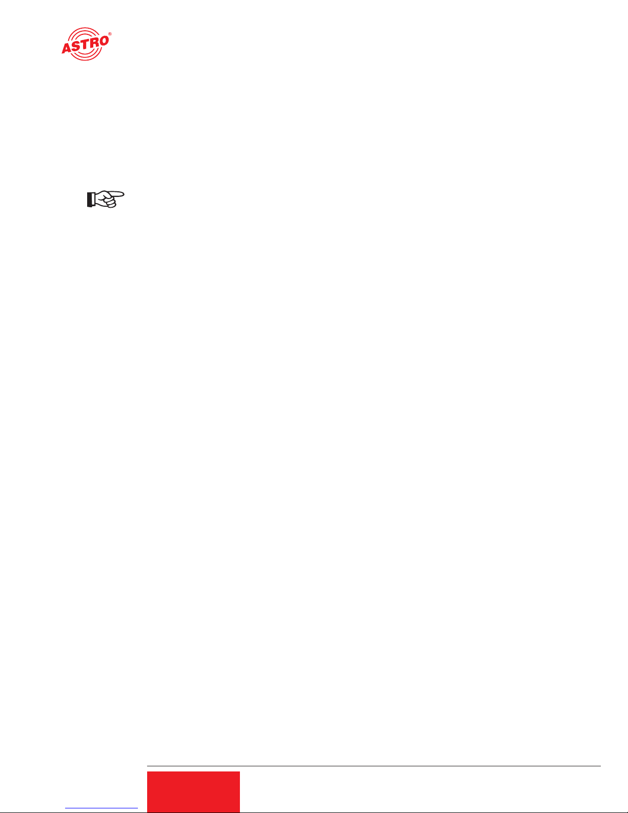
2.1 Description of functions
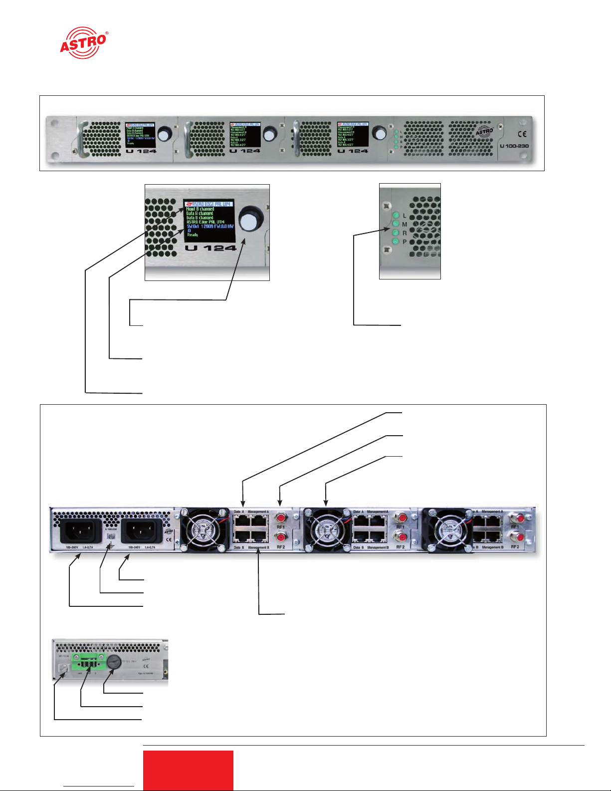
The U 100 series is used to convert IP data streams into CATV signals. The U 100-230 base
device can accommodate up to three U 1xx signal converters, as well as up to two U 100-SNTs
for supplying the voltage to the U 1xx signal converters. The U 124 receives up to four video data
streams encapsulated according to the internet protocol (IP) and converts them into up to 16
standardised FM output signals.
2.2 Safety instructions
Disconnect both mains plugs before opening the device!
The device must not be opened - for exceptions, see the maintenance and repair, and the service
tasks! Power supply units must not be opened!
The device must be connected to a power supply with an earth contact, and should be positioned
close to the mains socket.
The electrical system supplying current to the device, e.g. a house installation, must incorporate
safety devices against excessive current, short-circuiting and earth leakages in accordance with
EN 60950-1.
Both mains plugs are used to disconnect the device from the mains, therefore they must be
easy to access and use at all times. The device is already in operation when one power unit is
connected to the operating voltage. When the second power unit is also put into operation, one
of the power units runs in idle mode as long as the other unit is supplying power to the device.
The device may only be repaired by sending it to ASTRO along with a precise description of the
error.
Displays indicate the status of the device operation, as well as the existence of DC voltages
separate from the mains that are supplying the components of the device. However, operation
displays that are not lit up in no way indicate that the device is completely disconnected from the
mains or is voltage-free.
Read carefully:
EN 60 728 – Part 11, Safety requirements / No service tasks during electrical storms!
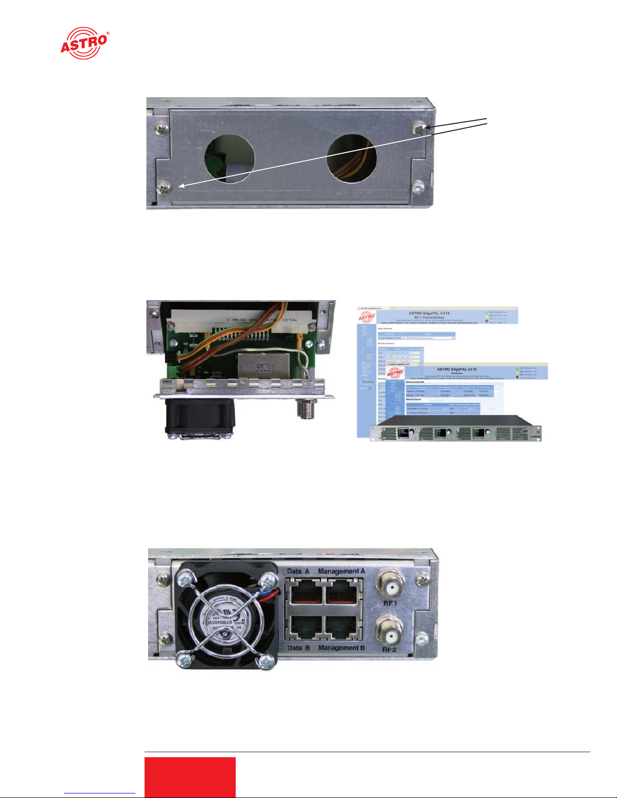
2.3 Assembly instructions
The U 100 base device may only be mounted using guide rails! If the device is only fastened by
means of the screws in the front panel, this will damage the base device!
The outputs of the signal converter must not be operated without connecting a combining network
or terminating impedance!
Protection from environmental factors:
The device must only be connected and operated in dry rooms. It must not be exposed to spray-
ing or dripping water, or to similar phenomena. If condensation appears, wait until the device is
completely dry. Objects containing liquid must not be placed on top of the device.
The permitted ambient temperature range is 0 … 45°C (ETS 300 019-1-3 class 3.1).
Mounting environment:
The device is designed for operation in, preferably, metallically conductive 19" racks with suffi-
cient air convection. It should be operated away from heat radiation and other heat sources. The
device my only be installed in rooms in which the permitted ambient temperature can be adhered
to, even under changing climatic conditions. To avoid trapped heat, it must be freely ventilated
on all sides. You absolutely must avoid mounting the device in a niche or covering the ventilation
openings.