Fiat Ducato User manual

FIATDUCATO
FACM0416_Ducato Supplementary.indd 1FACM0416_Ducato Supplementary.indd 1 20/4/22 12:16 pm20/4/22 12:16 pm
QUICK GUIDE

Dear Customer,
We would like to congratulate and thank you for choosing a Fiat Ducato.
This Quick Guide will provide you with the main indications and some recommendations for the use of your vehicle.
This Quick Guide is not a substitute for the more in-depth reading of the complete Owner Handbook, which is available online.
The figures in this guide are only examples. This might imply that some details of the image do not correspond to the actual
arrangement of your vehicle.
After reading it, you are advised to keep this Quick Guide inside the vehicle, for an easy reference and for making sure it remains
aboard the vehicle should it be sold.
In the attached Warranty Booklet you will also find a description of the Services that Fiat offers to its customers, the Warranty
Certificate and the detail of the terms and conditions for maintaining its validity.
We are confident that these tools will bring you closer to your new vehicle and make you appreciate the assistance provided by
the Fiat team.
Enjoy reading. Happy driving!

All data contained in this publication are intended to help you use your vehicle in the best possible way. FCA Italy S.p.A. aims at a
constant improvement of the vehicles produced. For this reason it reserves the right to make changes to the model described for
technical and/or commercial reasons. For further information, contact a Fiat Dealership.
ONLINE OWNER HANDBOOK
FCA is committed to protecting the environment and invites you to refer to the Complete Owner Handbook in digital form, via the
QR code on this page or on the internet pages listed below.
Go to the www.mopar.eu/owner website and access your personal area.
The “Maintenance and care" page includes all the information about your vehicle and the link to access eLUM, where you will find
all the details of the Owner Handbook.
Alternatively, to access this information, go to the Internet website at http://aftersales.fiat.com/elum/.
The eLUM website is free and conveniently allows you to browse the on-board handbooks of all other models of the Group,
among many other things.
Have a nice read and happy motoring!

3
ITALIANOENGLISH
CONTENTS
VEHICLE INTERIOR..................5
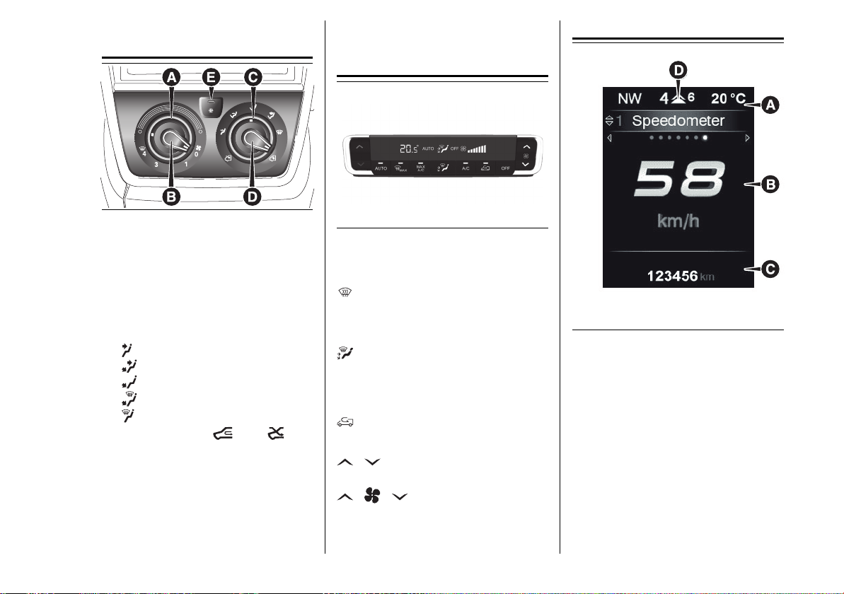
MANUAL CLIMATE
CONTROL SYSTEM..................6
AUTOMATIC CLIMATE
CONTROL SYSTEM..................6
3.5” DISPLAY.............................6
7” DISPLAY................................7
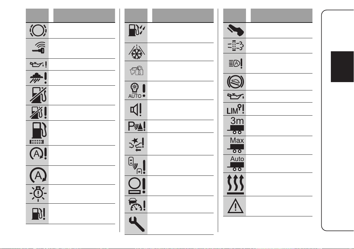
WARNING LIGHTS AND
MESSAGES ...............................7
RED WARNING LIGHTS/
SYMBOLS......................................7
AMBER WARNING LIGHTS/
SYMBOLS......................................8
GREEN WARNING LIGHTS/
SYMBOLS....................................10
BLUE WARNING LIGHTS/
SYMBOLS....................................10
WHITE WARNING LIGHTS/
SYMBOLS....................................10
GREY WARNING LIGHTS/
SYMBOLS....................................11
THE KEYS................................11
IGNITION DEVICE...................11
VERSIONS WITH ELECTRONIC
KEY..............................................11
VERSIONS WITH MECHANICAL
KEY..............................................11
DIGITAL REAR-VIEW
MIRROR...................................12
ELECTRIC PARKING BRAKE
(EPB) ........................................12
AUTOMATIC
TRANSMISSION......................13
EXTERNAL LIGHTS ................13
AUTO FUNCTION (Dusk sensor)...14
DIPPED BEAM HEADLIGHTS.......14
DAYTIME RUNNING LIGHTS
(DRL) (“Daytime Running Lights”)..14
FRONT/REAR FOG LIGHTS .........14
PARKING LIGHTS ........................14
"FOLLOW ME HOME" DEVICE.....14
HIGH BEAM HEADLIGHTS...........15
FLASHING THE HEADLIGHTS .....15
DIRECTION INDICATORS.............15
LANE CHANGE FUNCTION..........15
COURTESY LIGHTS.....................15
HEADLIGHT ALIGNMENT
CORRECTOR...............................15
HELP CALL..............................15
CHILD RESTRAINT
SYSTEMS ................................17
PASSENGER'S FRONT
AIRBAG AND CHILD RESTRAINT
SYSTEMS ....................................17
TPMS (Tyre Pressure
Monitoring System) ................19
DRIVING TIPS .........................20
CHANGING A WHEEL.............20
CHANGING PROCEDURE............20
FIX & GO AUTOMATIC
QUICK TYRE REPAIR KIT .....25
INFLATION PROCEDURE.............25
PROCEDURE FOR RESTORING
THE PRESSURE...........................27
CARTRIDGE REPLACEMENT.......27
FUSES......................................28
DASHBOARD FUSEBOX..............28
ENGINE COMPARTMENT
FUSEBOX.....................................29
WIRED MODULE..........................29
OPTIONAL WIRED MODULE........30
RIGHT CENTRAL PILLAR
OPTIONAL FUSEBOX ..................30
SCHEDULED SERVICING ......32
SERVICE SCHEDULE ..................32

4
REFUELLING...........................34
UCONNECT™ 5 ......................35
RADIO..........................................35
MEDIA..........................................35
CONTROLS ON THE STEERING
WHEEL E BEHIND THE
STEERING WHEEL.......................36
PAIRING A MOBILE PHONE.........36
UCONNECT™ .........................37
GRAPHIC BUTTONS ON
DISPLAY.......................................37
TOUCHSCREEN FUNCTION........37
USB SOURCE..............................38
APPLE CARPLAY AND
ANDROID AUTO...........................38
WIDGETS.....................................38
WHEELS ..................................39
COLD TYRE INFLATION
PRESSURE (BAR) ........................39
OFFICIAL TYPE
APPROVALS............................39
CONNECTED SERVICES........39
SUPPLEMENTS
FLAT-BED TIPPER................
SHUTTLE................................
DPF - FORCED
REGENERATION ...................
HEAVY DUTY........................
MINIBUS...............................
FRENCH POST OFFICE..........

5
ITALIANOENGLISH
VEHICLE INTERIOR
1 F1A0719
(A) LEFT STALK (External lights)
(B) DISPLAY
(C) RIGHT STALK (Windscreen wiper
and rear window wiper)
(D) Adaptive Cruise Control (ACC)
activation/deactivation
/ ACC distance regulation
LIM Speed Limiter (SL)
deactivation
SET+ CC/ACC/SL speed increase
SET- CC/ACC/SL speed reduction
CANC CC/ACC/SL settings delete
RES CC/ACC/SL settings reset
CONTROLS BEHIND STEERING
WHEEL
RIGHT SIDE - top/bottom button:
volume increase/decrease - central
button: Mute on/off
(E) DISPLAY AND TELEPHONE
COMMANDS
/ Scroll the display menu
/ Open information screens
and submenus
OK Open screens and confirm the
settings
Accept incoming calls
Voice commands
Refuse/end incoming call
CONTROLS BEHIND THE LEFT
SIDE OF THE STEERING WHEEL
- top/bottom button: search
tracks/stations - middle button:
select play source
(F) ELECTRIC PARKING BRAKE
(EPB)
2 F1A0720
(G) Uconnect™
(H) CLIMATE CONTROL SYSTEM
CONTROLS
(I) BUTTONS (Hazard warning lights,
ESC OFF, LaneSense OFF, Active
ParkSense, heated rear window
demisting/defrosting, doors lock/
unlock, Traction Plus, Hill Descent
Control) AND PASSENGER
AIRBAG ACTIVATION/
DEACTIVATION LED
(L) USB PORTS AND POWER
SOCKETS
(M) WIRELESS CHARGING
COMPARTMENT
(N) MANUAL/AUTOMATIC
TRANSMISSION

6
MANUAL CLIMATE
CONTROL SYSTEM
3 F1A0051
(A) Swivel ring for air mix temperature
setting (red = hot, blue = cold)
(B) Fan activation/setting knob
(0 = off, 1-2-3 ventilation speed,
4 = maximum speed)
(C) Swivel ring for air distribution
setting
face
face and feet
feet
windscreen and feet
windscreen
(D) Recirculation on or off
knob
(E) Climate control system on button
AUTOMATIC
CLIMATE CONTROL
SYSTEM
4 F1A0721
AUTO Activation/deactivation of
automatic climate control system
FRONT Windscreen heating
MAX A/C Activation/deactivation of
maximum cooling function
Press select air flow (face, face
and feet, feet, feet and windscreen,
windscreen)
A/C Climate control system on/off
Activate/deactivate recirculation
OFF Climate control system off
/ Temperature increase/
decrease
/ / Ventilation increase/
decrease
3.5” DISPLAY
5 F1A0659
(A) Headlight alignment position,
indication of the gear engaged,
outside temperature, compass
(where provided), date
(B) Vehicle speed, warning messages/
any failure warnings
(C) Total kilometres (or miles) run and
symbols of any failure indications
(D) Gear shift indication (GSI)

7
ITALIANOENGLISH
7” DISPLAY
6 F1A0657
(A) Driving assistance device
indications
(B) Multi-function dial indicator:
speedometer and driver
assistance system indication
(C) Seat belt status indication
(D) Yellow symbols
(E) GSI indications - reconfigurable
area
(F) Speedometer and driving
assistance device indications
(G) Red symbols
WARNING LIGHTS
AND MESSAGES
WARNING The instrument panel
warning light/symbol is accompanied
by a dedicated message and/or
acoustic warning (where provided).
These indications are indicative and
precautionary and as such must not
be considered as exhaustive and/
or alternative to the information
contained in the online Owner
Handbook, which you are advised to
read carefully in all cases. Always refer
to the information in this section in the
event of a failure indication.
WARNING Causes of ignition and
actions to be taken are illustrated in
detail in the online Owner Handbook.
However, the following actions are
briefly outlined in this Quick Guide:
(*) Contact a Fiat Dealership
(**) Repair immediately using the
dedicated “Fix & Go Automatic” kit
and contact a Fiat Dealership as soon
as possible
RED WARNING LIGHTS/
SYMBOLS
Warning
light Meaning
BRAKE FLUID LEVEL LOW
(*) / PARKING BRAKE
ENGAGED (*)
EBD FAILURE (*)
AIRBAG FAILURE
SEAT BELTS REMINDER
ENGINE COOLANT
TEMPERATURE TOO HIGH
ELECTRIC POWER
STEERING FAILURE (*)
ANTI-INTRUSION WARNING
HANDS NOT DETECTED ON
STEERING WHEEL
AIRBAG FAILURE (*)

8
Warning
light Meaning
LOW ENGINE OIL
PRESSURE
ALTERNATOR FAILURE (*)
INCOMPLETE DOOR/LOAD
COMPARTMENT CLOSURE
BONNET NOT PROPERLY
SHUT
AUTOMATIC
TRANSMISSION FAILURE
ATTENTION ASSIST
SYSTEM INTERVENTION
SELF-LEVELLING
SUSPENSION FAILURE
(where provided)
SEAT BELTS NOT
FASTENED
PARK ASSIST SYSTEM
PERMANENT FAILURE (*)
AUTONOMOUS EMERGENCY
BRAKE CONTROL
(AEB Control) SYSTEM
PERMANENT FAILURE
SPEED LIMIT EXCEEDED
AMBER WARNING
LIGHTS/SYMBOLS
Warning
light Meaning
HANDS NOT DETECTED ON
STEERING WHEEL
EOBD/INJECTION SYSTEM
FAILURE
INJECTION SYSTEM
FAILURE (*)
AdBlue® (UREA) INJECTION
SYSTEM FAILURE (*)
ABS FAILURE (*)
FUEL RESERVE
GLOW PLUG PREHEATING /
GLOW PLUG PREHEATING
FAILURE (*)
INDICATION OF AdBlue®
(UREA) DIESEL EMISSIONS
ADDITIVE LOW LEVEL
REAR FOG LIGHTS
Warning
light Meaning
ESC-ASR (*)/ TRACTION
PLUS (*)/ HILL HOLDER (*)
SYSTEM FAILURE
ESC-ASR / TRACTION PLUS
SYSTEM DEACTIVATION
START&STOP SYSTEM
MANUAL DEACTIVATION
LANE CONTROL SYSTEM
FAILURE (where provided) (*)
LANE CONTROL SYSTEM
(where provided) -
Approaching lane limit line
TPMS SYSTEM FAILURE (*) /
TYRE PRESSURE LOW
FULL BRAKE CONTROL
SYSTEM TRIGGERED OR
FAILURE (*)
FULL BRAKE CONTROL
SYSTEM MANUAL
DEACTIVATION OR
RESTARTING
ATTENTION ASSIST
SYSTEM INTERVENTION
FAILURE (*)
BRAKE LIGHT FAILURE

9
ITALIANOENGLISH
Warning
light Meaning
BRAKE PAD WEAR
KEYLESS ENTRY SYSTEM
FAILURE (*)
ENGINE OIL PRESSURE
SENSOR FAILURE
RAIN SENSOR FAILURE (*)
FUEL CUT-OFF SYSTEM
OPERATION
FUEL CUT-OFF SYSTEM
FAILURE (*)
FUEL FILTER (where
provided) (*)
START&STOP SYSTEM
FAILURE (*)
START&STOP SYSTEM
FAILURE / PRESS CLUTCH
PEDAL (*)
EXTERNAL LIGHTS FAILURE
FUEL LEVEL SENSOR
FAILURE (*)
Warning
light Meaning
WATER IN DIESEL FUEL
FILTER
POSSIBLE ICE ON ROAD
FIAT CODE SYSTEM
FAILURE (*)
DUSK SENSOR FAILURE (*)
SOUND SYSTEM FAILURE
(*)
PARK ASSIST SYSTEM
TEMPORARY FAILURE
AUTONOMOUS EMERGENCY
BRAKE CONTROL
(AEB Control) SYSTEM
TEMPORARY FAILURE (*)
BLIND SPOT ASSIST (BSA)
SYSTEM FAILURE (*)
TRAFFIC SIGN
RECOGNITION SYSTEM
FAILURE (where provided) (*)
ADAPTIVE CRUISE
CONTROL (ACC) FAILURE
(where provided) (*)
SCHEDULED SERVICING
(SERVICE) (*)
Warning
light Meaning
CLUTCH PEDAL
DPF (particulate filter)
CLEANING underway
AUTOMATIC HIGH BEAM
HEADLIGHTS FAILURE (*)
HILL DESCENT CONTROL
(where provided)
DEGRADED ENGINE OIL
(where provided) (*)
SPEED LIMITER FAILURE (*)
TRAILER LENGTH (“AUTO”
SETTING)
MAXIMUM TRAILER
LENGTH
AUTOMATIC TRAILER
LENGTH
FUEL CUT-OFF CIRCUIT
BREAKER OF THE
ADDITIONAL HEATER
TRIPPED (where provided)
GENERAL FAILURE
INDICATION (*)

10
GREEN WARNING
LIGHTS/SYMBOLS
Warning
light Meaning
DIPPED BEAM
HEADLIGHTS / FOLLOW ME
HOME
LANE CONTROL SYSTEM
(where provided) - System
active
LEFT DIRECTION
INDICATOR
RIGHT DIRECTION
INDICATOR
FOG LIGHTS
CRUISE CONTROL
AUTOMATIC HIGH BEAM
HEADLIGHTS (Automatic High
Beam / High Beam Control)
TRACTION PLUS SYSTEM
ACTIVATION
SEAT BELTS FASTENED
ELECTRONIC CRUISE
CONTROL
Warning
light Meaning
LIM SPEED LIMITER ON
INTELLIGENT SPEED
ASSIST SYSTEM
ACTIVATION (where
provided)
START&STOP SYSTEM
MANUAL ACTIVATION /
START&STOP SYSTEM
TRIGGERED
BLUE WARNING LIGHTS/
SYMBOLS
Warning
light Meaning
HIGH BEAM HEADLIGHTS
WHITE WARNING
LIGHTS/SYMBOLS
Warning
light Meaning
LANE CONTROL SYSTEM
(where provided) - Lane limit
lanes not found
ADAPTIVE CRUISE
CONTROL (ACC) ACTIVE
(where provided)
HEADLIGHT HEIGHT
Warning
light Meaning
SINGLE GEAR SHIFT
INDICATION (SHIFTING UP)
SINGLE GEAR SHIFT
INDICATION (SHIFTING
DOWN)
DOUBLE GEAR SHIFT
INDICATION (SHIFTING UP)
DOUBLE GEAR SHIFT
INDICATION (SHIFTING
DOWN)
HILL DESCENT CONTROL
(where provided)
SPEED LIMIT EXCEEDED
LIM SPEED LIMITER READY
TOWING A TRAILER
TRAILER TOWING FAILURE
(*)
ECO "DRIVE MODE” FUNCTION
(versions with manual
transmission)

11
ITALIANOENGLISH
Warning
light Meaning
ECO
or
PWR
"DRIVE MODE” FUNCTION
(versions with automatic
transmission)
GREY WARNING LIGHTS/
SYMBOLS
Warning
light Meaning
ADAPTIVE CRUISE
CONTROL (ACC) NOT
ACTIVE (where provided)
LIM SPEED LIMITER ON
THE KEYS
1)
1) 2)
ATTENTION
1) Do not swallow the battery. Danger of
chemical burns. The keys contain a small
battery. If the battery is swallowed, it can
cause severe internal burns in just 2 hours
and cause death. Keep new and used
batteries out of the reach of children. If
the battery compartment does not close
securely, discontinue use of the product
and keep it out of reach of children. If
you believe that batteries may have been
swallowed or inserted inside the body,
seek medical attention immediately.
WARNING
1) Do not place the keys of the vehicle in
the wireless charging compartment(M)
fig.2: risk of access and starting system
malfunction.
2) Do not place contactless cards (RFID),
credit cards or metal objects in the
charging compartment.
IGNITION DEVICE
VERSIONS WITH
ELECTRONIC KEY
7 F1A0610
STOP: engine off, steering column
locked
ENGINE: driving position
START: motor starting
2) 3) 4) 5)
Starting the engine (with the electronic
key battery flat): place the rounded
edge of the electronic key (the side
opposite the metal insert) on the
ignition device and press the button
with the electronic key.
NOTE Refer to the "Starting the
engine" chapter in the "Starting
and driving" section of the Owner
Handbook for more information.
VERSIONS WITH
MECHANICAL KEY
8 F1A0009
STOP: engine off, key can be
removed, steering column locked
MAR: driving position
AVV: engine starting

12
ATTENTION
2) Always remove the key and lock the
vehicle when leaving it.
3) For various reasons, it is dangerous
to leave children unattended in a vehicle.
Children or other people may seriously,
or even fatally, injure themselves. Do not
allow children to touch the parking brake,
brake pedal or gear lever.
4) It is extremely dangerous to leave
children or animals inside the parked
vehicle when the external temperature is
very high. The heat inside the passenger
compartment may have serious, or even
fatal, consequences.
5) Do not remove the mechanical
key while the vehicle is moving as the
steering wheel is locked automatically
as soon as the key is turned. This also
applies when vehicles are being towed.
DIGITAL REAR-VIEW
MIRROR
9 F1A0619
(A) On/Off control lever
(B) Menu button
(C) Left scroll button
(D) Right scroll button
Button at the side of the lever:
Brightness
Vertical angle
Horizontal movement (where
provided)
WARNING Support function intended
to improve the view of the road
behind, but that does not provide
a complete view of the surrounding
environment.
The combination of a digital rear-view
mirror and rear camera with dynamic
guidelines (where provided) makes
it possible to visually check the area
behind the vehicle in order to perform
manoeuvres more safely.
ELECTRIC PARKING
BRAKE (EPB)
10 F1A0649
Engagement procedure:
Manual: by pulling the switch fig.10
Automatically in "Safe Hold" or
"Auto Park Brake" conditions
Operating mode:
Dynamic operating mode
Static and release engagement
mode
Drive Away Release
Safe Hold
Auto Park Brake

13
ITALIANOENGLISH
AUTOMATIC
TRANSMISSION
11 F1A0665
The gear lever (A) fig.11 has the
following positions:
P = Park
R = Reverse
N = Neutral
D = Drive (automatic forward travel
AutoStick:
+ shifting up in sequential driving
mode
– shift down in sequential driving
mode
The lever must only be moved from P
to D when the vehicle is stationary and
the engine at idling speed.
To shift the gear lever from P to any
other position, with the ignition device
on MAR, press the brake pedal and
the button on the lever. The gear lever
can be shifted freely from R to N or D,
while the button on the lever must be
pressed with the engine idling to shift
from R to P. To shift from N to D or R,
you need to press the brake pedal.
Before leaving the vehicle, engage
the electric parking brake and then
move the gear lever to P, otherwise it
may be difficult to move the gear lever
out of the P position. After parking,
always move the gear lever out of
the P position before disengaging the
electric parking brake.
EXTERNAL LIGHTS
6) 7)
12 F1A0851
13 F1A0852

14
14 F1A0609
AUTO FUNCTION (Dusk
sensor)
This system (where provided) switches
the headlights on/off automatically
according to the environmental light.
Turn the stalk ring (A) to position
fig.14 or to position AUTO fig.13
(where provided).
DIPPED BEAM
HEADLIGHTS
Ignition device on MAR and stalk ring
on . The warning light switches
on in the instrument panel.
DAYTIME RUNNING
LIGHTS (DRL) (“Daytime
Running Lights”)
Starting device in MAR position and
stalk ring (A) in fig.12, or AUTO
fig.13, or fig.14 (where provided).
FRONT/REAR FOG
LIGHTS
Use button (A) fig.15:
first press: front fog lights and side
lights switch on if the dipped beam
headlights are off. Only front fog
lights switch on if the dipped beam
headlights are on. The warning
light on the instrument panel turns
on
second press: turns on the rear
fog lights, the warning light on the
instrument panel will turn on
third press: front/rear fog lights
and side lights switch off if dipped
beam headlights are off. Fog
switch off if the dipped beam
headlights are on
fourth press: rear fog lights switch
off if dipped beam headlights are
on.
15 F1A0689
PARKING LIGHTS
Ignition device in STOP position or key
removed, stalk ring (A) fig.14 first in
position fig.12, or AUTO fig.13,
or fig.14 (where provided) and
then in .
The warning light switches on in
the instrument panel.
"FOLLOW ME HOME"
DEVICE
Activation
Ignition device in the STOP position.
Pull the left stalk as if flashing the high
beam headlights; each movement of
the stalk corresponds to an increase
of 30 seconds in the headlight switch-
off delay, up to a maximum of 210
seconds.

15
ITALIANOENGLISH
Deactivation
Keep the left stalk in high beam
headlight flashing mode for a few
seconds.
HIGH BEAM
HEADLIGHTS
With the ring in position , push the
left stalk forward. The warning light
on in the instrument panel turns on.
Pull the stalk to switch them off.
FLASHING THE
HEADLIGHTS
Pull the left stalk (the position is not
stable). The warning light on in the
instrument panel turns on.
DIRECTION INDICATORS
Move the left stalk to the stable
position:
upwards: activates right direction
indicator
downwards: activates the left
direction indicator
Warning light or will blink on
the instrument panel.
LANE CHANGE
FUNCTION
If you wish to signal a lane change,
place the left stalk in the unstable
position for less than half a second.
The direction indicator on the side
selected will be activated for 5 flashes
and then go out automatically.
COURTESY LIGHTS
With the ignition device in the STOP
position, the side lights and number
plate lights can be activated for a
time of 30, 60 or 90 seconds. This
function can be regulated from the
display menu or from the Uconnect™
system.
HEADLIGHT ALIGNMENT
CORRECTOR
Contact a Fiat Dealership to have the
headlights’ direction checked and
adjusted.
With the ignition device on MAR and
dipped headlights on, press the
and buttons on the panel on the
bottom of the dashboard on the driver
side.
ATTENTION
6) The daytime running lights are an
alternative to the dipped headlights for
driving during the daytime in countries
where it is compulsory to have lights
on during the day; where it is not
compulsory, the use of daytime running
lights is permitted.
7) Daytime running lights cannot replace
dipped beam headlights when driving
at night or through tunnels. The use
of daytime running lights is governed
by the highway code of the country in
which you are driving. Comply with legal
requirements.
HELP CALL
The vehicle is equipped with on-
board assistance functions designed
to provide support in the event of an
accident and/or emergency (HELP).
They are managed via the Uconnect
Box.
The HELP function is activated:
automatically in the event of a
major collision recorded by the
device aboard the vehicle

16
manually, by pressing the HELP
button located on the ceiling
light (for versions/markets, where
provided) or by means of the
dedicated menu on the system
Uconnect™
WARNING If the HELP emergency
service is activated, the call will be
routed automatically to a private
call centre. Note that whenever
the text refers to the HELP call, it
is to be considered managed by
private service providers. The HELP
call service is not the e-call system
for emergency calls set out in the
applicable European Community
legislation for newly type-approved
vehicles.
The HELP function is activated with:
the ignition device is at MAR
ignition device in STOP position
and Uconnect™ system display
on
After the HELP function (for versions/
markets, where provided) has been
activated automatically or manually,
pressing the corresponding button
will send the position data to the
operational centre and make a voice
call to an operator.
NOTE If the HELP function does not
work, a system fault will be indicated
on the display. If this happens, go to
an authorised workshop to have the
function repaired as soon as possible.
NOTE Correct operation of the HELP
services will only be guaranteed with
good network coverage.
WARNING The HELP function may
not be available for the first minute
after the vehicle is started.
Privacy: GPS location is always
active for HELP. Deactivating it via the
“Settings” menu of the Uconnect™
system will make some other services
unavailable (see the “Settings” chapter
of the Uconnect™ system in the
Owner Handbook for more details).
WARNING The icon at the top
of the Uconnect™ system display
indicates that the geolocation function
is active (ON). When geolocation is
on, the vehicle position is tracked to
enable the functions that require it.
When geolocation is off, the vehicle
position is only tracked by the
navigation, safety, insurance and driver
assistance systems (where provided).
See the Uconnect™ system
"Settings" chapter in the Owner
Handbook to deactivate the function.
If the system is unable to establish
the voice call, or the line disconnects
because of insufficient coverage,
the HELP service will try to call the
operational centre again for 5 minutes.
If the HELP call system detects a
malfunction, it will be indicated:
in the start-up phase
at the moment when the
malfunction is detected
by turning on the red LEDs on
the ceiling light and displaying a
message on the display of the
Uconnect™ system. Contact
a Fiat Dealership as soon as
possible
NOTE Ignoring system fault warnings
could mean being unable to make an
HELP call when necessary.

17
ITALIANOENGLISH
CHILD RESTRAINT
SYSTEMS
8) 9) 10) 11) 12) 13) 14) 15) 16) 17) 18) 19)
For optimal protection in the event
of an impact, all occupants must
be seated and wearing adequate
restraint systems, including newborn
and other children! This prescription
is compulsory in all EC countries
according to EC Directive 2003/20/
EC.
PASSENGER'S FRONT
AIRBAG AND CHILD
RESTRAINT SYSTEMS
Rearward facing child restraint
systems must NEVER be fitted on the
front seat with an active passenger
side bag since in the event of an
impact the airbag activation may
cause fatal injuries to the transported
child.
ALWAYS comply with the instructions
on the label stuck on the passenger
side sun visor fig.16.
16 F0T0950
Manual deactivation of front
passenger side airbag and side
bag
The LED that corresponds to
the symbol (A) fig.17 on the
dashboard indicates the passenger's
protection status. If the LED is off, the
passenger side protection is activated.
When the front passenger airbag and
side bag (for versions/markets, where
provided) are activated again, the
warning light turns off.
17 F1A0647
IMPORTANT NOTE To manually
deactivate the front passenger
airbag and access the “Safety” –>
"Passenger airbag” page of the
instrument panel menu via the steering
wheel controls, scroll up or down with
the / buttons until "Passenger
AIRBAG ON” is displayed, and press
the OK button on the steering wheel
to confirm deactivation.

18
ATTENTION
8) Do not place a rearward-facing cradle
seat on the front seat if the passenger
side airbag is enabled. Deployment of
the airbag in a crash could cause fatal
injuries to the child regardless of the
severity of the collision. It is advisable to
always carry children in a child restraint
system on the rear seat, which is the
most protected position in the event of a
collision. If you need to carry a child on
the front passenger seat in a rear-facing
cradle restraint system, the passenger
side airbags (front and side bags for
chest/pelvis protection, for versions/
markets, where provided) must be
deactivated using the setup menu. It is
important to check the dedicated LED
on button on the dashboard to make
sure that they are actually deactivated.
Move the passenger's seat as far back
as possible to avoid contact between the
child seat and the dashboard.
9) The sun visor bears a label with
suitable symbols reminding the user
that it is compulsory to deactivate the
airbag if a rearward facing child restraint
system is fitted. Always comply with
the instructions on the passenger-side
sun visor (see information in the Owner
Handbook).
10) Do not move the front or rear
seat if a child is seated on it or on the
dedicated child restraint system.
11) Incorrect fitting of the child
restraint system may result in an
inefficient protection system. In the
event of an accident the child restraint
system may become loose and the
child may be injured, even fatally.
When fitting a restraint system for
newborns or children, strictly comply
with the instructions provided by the
Manufacturer.
12) When the child restraint system
is not used, secure it with the seat
belt or with the ISOFIX anchorages,
or remove it from the vehicle. Do not
leave it unsecured inside the passenger
compartment. In this way, in the event of
sudden braking or an accident, it will not
cause injuries to the occupants.
13) Always make sure that the diagonal
section of the seat belt does not pass
under the arms or behind the back of
the child. In the event of an accident the
seat belt will not be able to secure the
child, with the risk of injury, including fatal
injury. Therefore the child must always
wear the seat belt correctly.
14) The diagrams are indicative and
provided for assembly purposes only. Fit
the child restraint system according to
the instructions, which must be included.
15) Car seats for weight groups 0 and 1
feature an anchor in front of the vehicle
safety belts as well as its own belts to
restrain the child. Due to their weight,
they may be dangerous if incorrectly
mounted (e.g. if fastened to the vehicle
seat belts placing a cushion in between).
Follow the assembly instructions
carefully.
16) Fit the child restraint system only
when the vehicle is stationary. The child
restraint system is correctly fixed to
the brackets when you hear the click.
Follow the instructions for assembly,
disassembly and positioning that the
Manufacturer must supply with the child
restraint system.
17) Fiat Professional recommends fitting
the child restraint system according to
the instructions, which must be included.
18) Do not use the same lower
anchoring to install more than one child
restraint system.
19) If a Universal ISOFIX child restraint
system is not fixed to all three
anchorages, it will not be able to protect
the child correctly. In an accident, the
child could be seriously or fatally injured.

19
ITALIANOENGLISH
TPMS (Tyre
Pressure
Monitoring System)
20) 21) 22) 23) 24) 25) 26) 27) 28)
The tyre pressure monitoring system
(TPMS) warns the driver of low tyre
pressure on the basis of the cold
inflation pressure prescribed for the
vehicle.
Changes in external temperature
may cause tyre pressure to vary.
This means that a decrease in the
external temperature corresponds to a
decrease in the tyre pressure.
Tyre pressure must always be
adjusted according to the cold inflation
pressure. Cold tyre inflation pressure
is the tyre pressure after letting the
vehicle stand for at least three hours
or a travel shorter than 1.6km after an
interval of three hours.
The cold tyre inflation pressure must
not exceed the maximum inflation
pressure value printed on the side of
the tyre.
The tyre pressure also increases while
driving the vehicle: this is a normal
condition and does not require any
adjustment of the pressure.
The TPMS continues to advise
the driver of the low tyre pressure
condition until this is corrected; the
warning continues until the pressure
corresponds or exceeds the pressure
prescribed for the cold tyres.
Therefore, if insufficient tyre pressure
is indicated (warning light on
instrument panel on), increase the
inflation pressure up to the prescribed
cold inflation value.
After the automatic update of the
system, the tyre pressure control
warning light switches off. If the
vehicle has been stopped with the
engine off for at least 20 minutes,
you may need to drive the vehicle for
about 20 minutes at a speed higher
than 20km/h to allow the TPMS to
receive this information.
NOTE The TPMS is not intended
to replace normal tyre care and
maintenance, nor to warn of tyre
failures. The TPMS should not be
used as a tyre pressure gauge while
adjusting your tyre pressure.
ATTENTION
20) The TPMS is optimised for the
original tyres and wheels provided.
TPMS pressures and alerts have been
defined according to the size of the
tyres mounted on the vehicle. Using
equipment with different size, type
or kind may cause irregular system
operation or sensor damage. Non-
original spare wheels can damage
the sensor. Do not use tyre sealant
or balancing weights if the vehicle is
equipped with TPMS as these may
damage the sensors.
21) If the system signals a pressure drop
on a specific tyre, it is recommended to
check the pressure on all four tyres.
22) The TPMS does not relieve the
driver from the obligation to check the
tyre pressure every month; it is not to
be considered a replacement system for
maintenance nor a safety system.
23) Tyre pressure must be checked with
tyres cold. Should it become necessary
for whatever reason to check pressure
with warm tyres, do not reduce pressure
even though it is higher than the
prescribed value, but repeat the check
when tyres are cold.
24) The TPMS cannot indicate sudden
tyre pressure drops (for example
when a tyre bursts). In this case, stop
the vehicle, braking with caution and
avoiding abrupt steering.
Other manuals for Ducato
7
Table of contents
Other Fiat Automobile manuals

Fiat
Fiat 2015 500 Abarth User manual

Fiat
Fiat BLUE&ME 2012 500c User manual

Fiat
Fiat Doblo User guide

Fiat
Fiat PUNTO User guide

Fiat
Fiat 124 Spider User guide

Fiat
Fiat 2016 500X User manual

Fiat
Fiat PANDA User guide

Fiat
Fiat Croma User manual

Fiat
Fiat 1993 Cinquecento 899 CAT Product guide

Fiat
Fiat Blue&Me 2012 500 Abarth User manual
Popular Automobile manuals by other brands

Pontiac
Pontiac 1998 Grand Prix owner's manual

Mercedes-Benz
Mercedes-Benz GLA 2018 Operator's manual

Mercedes-Benz
Mercedes-Benz C-Class 2014 owner's manual

Mercedes-Benz
Mercedes-Benz E CLASS 2020 Operator's manual

Mitsubishi
Mitsubishi Outlander Plug-in hybrid quick guide

Toyota
Toyota Prius Prime 2015 owner's manual