FIBER FOX MINI 4R User manual
This User Manual explains the use, performance characteristics, and cautions about MINI4R
fusion splicer and how to install and operate it. The primary goal of this manual is to make the
user as familiar with the splicer as possible.

Chapter 3 Basic operation 14
Chapter Two Installation 6
1.1 Applied fiber type 4
1.2 Splice Loss 4
1.3 Splice mode 4
1.4 Fiber heating groove 4
1.5 Power supply 4
1.6 Size and weight 4
1.7 Environment Condition 5
5 rehtO 8.1
2.1 Safety warning and prevention measures 6
2.1.1 Operating safety warns 6
2.1.1 Operating safety warns 7
2.1.2 Maintenance and appearance protect 7
2.1.3 Transportation and Storage 7
2.2 Installation 8
2.2.1 Unpack 8
2.3 Appearance overview 9
2.4 Power supply mode 10
2.4.1 Two types of power supply mode 11
2.5 Battery charge 11
2.5.1 Charging process 11
2.5.2 Two kinds of charging methods 11
2.5.3 Battery state 12
2.6 Battery activate 13
2.7 Heating groove 13
Technical Parameters 4
Chapter 1 4
catalogue

3.1 How to use HCK construction toolbox workbench 14
3.2 Power connection 14
3.3 Battery operation 15
3.4 Starting up 15
3.4.1 Adjust the position of displayer 15
3.4.2 Adjust the brightness of LCD backlight 16
3.5 Fiber prepare 16
1. Clean the fiber 16
2. Install the fiber heat-shrinkable tubing 16
3.Strip and clean the fiber 16
4.Cut the fiber 17
3.6 Splice operation 17
3.6.1 Put fiber 17
3.6.2 Check fiber 18
3.6.3 Splice 18
Chapter 4 Splice Procedure 19
4.1 Display effective splice procedure 19
4.2 Select splice procedure 20
4.3 General splice procedure 21
4.3.1 Prefusing 21
4.3.2 Splice 21
4.3.3 Splice process 21
4.4 Splice parameter of general splice process 22
6.1 Heating template 25
6.2 Select heating mode 25
6.3 Edit the heating mode 25
Chapter 6 Heating Mode 24
Chapter 5 Splice option 23

Chapter 7 Maintenance Menu 27
6.5 Heating mode parameter 26
6.5 Heating mode parameter 26
7.5 Electrical machine alignment 29
7.6 Discharging alignment 29
7.7 Electrode setting 30
7.8 Software upgrading 30
7.4 Dust examination 29
7.1 Replace the electrode 27
7.2 Electrode stabilize 28
7.3 Autodiagnosis test 28
Chapter 8 Other functions and application 31
8.1 Data storage 31
8.1.1 Display splice record 31
8.1.2 Delete the splice record 31
8.1.3 Splice data storage 31
8.2 System setting 31
8.2.1 The displayer position 31
8.2.2 Energy saving position 32
8.2.3 System information 32
Appendix A: The reasons of high splicing loss and its solutions 33
Appendix B Error information sheet 34
Appendix C Common faults and solutions 36

Use the same fiber to continue, if adopt ITU-T standard insertion method to
measure its splice loss, the typical value is:
◆SM:0.05dB
◆MM:0.02dB
◆DS:0.08dB
◆NZDS:0.08dB
1.2 Splice Loss
◆External direct mains input: input voltage is 12V, input current 3A
◆Lithium battery supply: 12V, 5.2Ah, full charging time is about three hours.
1.5 Power supply
◆Size: Length*Width*Height=124mm*123mm*138mm
◆Weight:1.9kg (Battery included)
1.6 Size and weight
◆100 kinds of modes can be stored and 39 kinds of splice modes can be preset
◆2000 pieces of latest splice results record can be internally stored.
1.3 Splice mode
◆Heating time: 20 to 900s for choose
◆Typical heating time: 30s
◆Heating mode: 32 kinds of heating mode and 5 types of heating mode can be
preset
1.4 Fiber heating groove
◆SM(ITU-TG.652)/MM(ITU-TG.651)/DS(ITU-TG.653)/NZDS(ITU-TG.655)
/ITU-TG.657A/ITU-TG.657B
◆Applied cores: one to four cores
1.1 Applied fiber type
Chapter 1 Technical Parameters

◆Observe and display method: Two cameras, 4.3 inch color liquid crystal
screen (High intensity resistant protective layer on its surface)
◆One to four cores X and Y amplify 38 times, five to eight cores X and Y
amplify 28 times and nine to twelve cores X and Y amplify 18 times.
◆Strain relief test: 1.96-2.25N
◆Port:
1.8 Other
◆Operating conditions: Temperature: -10℃- 50℃; Humidity: 0-95%;
Altitude:0-2000m; Maximum wind speed: 15m/s
◆Storage environment: temperature: -10℃- 50℃; Humidity: 0 -95%;
Battery:-20℃--30℃for long time storage
1.7 Environment Condition
Internally installed, back apron inner side, SD card start, store program
SD card port
Serial port
Mini Hdmi port
Internally installed, back apron inner side, conduct debugging
External installed
Mini USB: Encryption and data transmission
USB 2.0: Software upgrading and image preserve
HS-12 : USB charge function
Port
Description

Chapter Two Installation
1). Please not use Fusion splicer in flammable and combustible place.
2) Please not touch the electrode when open the machine.
Note: Only special electrode bar can be used on Fusion splicer . When you need
to replace the electrode, please choose replace electrode option on maintenanc e
menu, or you must turn off the power ahead of time. Discharging operation is strictly
forbidden if couple electro de bars haven’t been installed.
2.1.1 Operating safety warns
2.1 Safety warning and prevention measures
Fumes, peculiar smell, abnormal sound or heating abnormal.
Liquid or foreign matters fall into the inner of Fusion splicer.
Fusion splicer suffered from strong vibration or impact.
I t is very important that M INI4R i s designed f or splice quartz glass f iber, not
applied for any other purpose. S ince Fusion splicer i s point-device m achine, you
should be seriously cautious when carry it. So, please keep strictly to the following
safety rules and general specification when you use and carry M INI4R. M anners
don’t take t hese safety m easurements or don’t comply w ith the warnings and
attention matters that this manual offered will violate the security standard of fusion
splicer design, manufacture and practical use.
Fiber Box assumes no responsibility due to violate the requirements.
3). Please not dismantle any part of Fusion splicer except the elements which can
be replaced b y users permitted in t his manual, components renewal o r internal
alignments can only be conduct by F iber Fox o r maintenance s taff authorized b y
Fiber Fox.
4) Please be careful when connect battery adapter cable, don’t pull the cable when
take it down from the socket, just hold the plug. Please make sure the cables are in
good condition for fear from the risk of fire or electric shock accidents.
5) Please not expose Fusion splicer to fire, electric shock or humidity environment.
6) P lease w ear p rotective g lasses when p repare fiber and i n splice course,
otherwise fiber scrap enter into your eyes, fall on your skin or swallow will lead to
serious outcomes.
7) When the following cases occurred, please turn off the Splicer and pull out the
adapter immediately, otherwise it will lead to serious consequences, such as Fusion
splicer will work abnormally or beyond repair.

2.1.2 Maintenance and appearance protect
1) Avoid using hard articles to clean V groove and electrode bar.
2) Avoid using acetone, painted diluents or alcohol to clean any part of the Fusion
splicer unless after careful consideration.
3) Please use dry cloth to clean the dust and dirt.
4) If the external appearance of the fusion splicer is very dirty, you can put soft
cloth into diluted cleaning fluid and then do the cleaning. Then use dry cloth to dry
the machine. Please not use furniture lighting material or other detergent.
5) Please adhere to the maintenance method that this manual introduced.
8) Please not use compress o r canned gas detergent t o clean Fusion splicer,
otherwise the arc produced in splice course will light the inflammable goods left.
9) P lease j ust use exclusive F iber Fox A C adapter. Inappropriate a lternating
current power supply will lead to fumes, electric shock or facility damage; even it
will result in fire accident, body hurt and death.
10). Please j ust use exclusive A C power cord. W eighty items should not be
placed on the power line, please not let power line heated or change the power
line. Inappropriate or damaged power line will lead to fumes, electric shock and
facility damage; even it will result in fire accident, body hurt or death.
2.1.3 Transportation and Storage
1)When move Fusion splicer to warm place from cold environment, try to adopt
gradual warming mode, otherwise condensation will be produced in the inner of
the device, thus will do adverse effects to it.
2)Please pack it when you don’t use it.
3)Please keep Fusion splicer clean and dry.
4)Fusion splicer have been precisely calibrate and alignment, please place it in
carrying case f or f ear i t will b e damaged o r polluted, p roper b uffer box shook
should be needed during long-distance transportation.
5)Please avoid direct sunlight or put it in overheated environment.
6)Keep the minimum humidity when preserve, relative humidity should be l ess
than 95%.

2.2 Installation
Hold the handle of the Fusion splicer upward and take it out. Please refer to the
following picture.
2.2.1 Unpack
2.2.2 Standard configuration of MINI4R Fusion splicer (depend on the goods as criterion)
MINI4R tool box/1/standard
configuration
MINI4R special fixture of heat
melt connector/one set/optional
Random user CD/standard
configuration
Battery/one piece
/standard configuration
Charger and adapter/one
/standard configuration
MINI4R Fusion splicer/one
piece/Standard configuration
1
2
3
4
5
6
7
Cooling rack
Power line(EU/UK/US)/one
/standard configuration
Cutting knife
Heat strip machine
Electrode bar (two pairs)
Important.
Please keep to the following explanations carefully.
Mini 4R
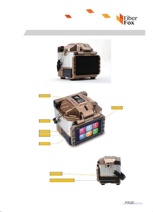
2.3 Appearance overview
09
Side
Charger connect
USB port
Battery
Carry handle
ON/OFF
Operating button
Hot stove
Battery
Table of contents
Other FIBER FOX Network Hardware manuals

Popular Network Hardware manuals by other brands

Matrix Switch Corporation
Matrix Switch Corporation MSC-HD161DEL product manual

B&B Electronics
B&B Electronics ZXT9-IO-222R2 product manual

Yudor
Yudor YDS-16 user manual

D-Link
D-Link ShareCenter DNS-320L datasheet

Samsung
Samsung ES1642dc Hardware user manual

Honeywell Home
Honeywell Home LTEM-PV Installation and setup guide


