FIBER FOX Mini 6SI User manual

- 1 -
Mini 6S
User Manual
I

- 2 - - 3 -
Contents
Introduction
Technical specifications
Splicer description & Part name
How to the replace the fiber folder
Cleaning
Splice Program
Appendix I
Appendix II
Appendix III
- Stabilize Electrodes
- Arc Calibration
- Splice Menu
- Maintenance
- Setting
1) Splice Mode
2) Splice Option
3) Heater Mode
4) Data Storage
5) Menu Lock
1) System Setting
2) Language
3) Power Save Option
4) Set Calendar
5) Password
6) System Information
Important
FIberFox highly recommends all users to read this manual before operating Mini 6S.
This manual is valid for the following software version.
4
4
6
7
7
24
26
29
9
10
11
12
13
8
8
18
19
20
21
21
22
·
·
·
·
·
·
·
·
·
- 4 - - 5 -
Introduction
Technical specifications
Thanks for choosing Mini 6S FTTx Master from FiberFox. The Mini 6S with innovative design and
exquisite manufacturing technology gives customers unexperienced convenience.
Unprecedented splicing experience and new technology greatly reduces splicing and heating
time. Advanced estimate method and core alignment technique ensure the accuracy of splice loss
estimation. Its small size, compact design and reliable protection shell make it suitable for any
operating environment. Dynamic operation interface and automatic splice mod give the customers
grat convenience. For more information, please contact your local distributor or visit our website at
www.fiberfox.co.kr
This manual explains the features, specifications, operation, maintenance and warnings about Mini
6S. The primary goal of this manual is to make the user as familiar with the splicer as possiblse.
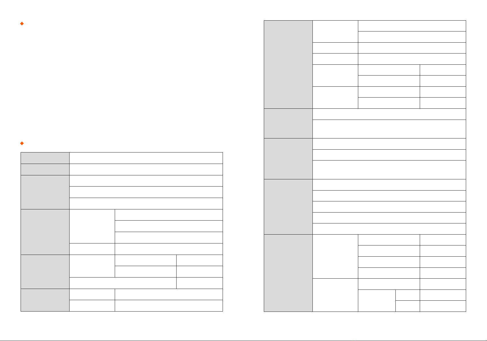
Camera High precision dual camera
Display 4.3” wide color reinforced LCD
Microscope
x150 : X&Y axis dual view
x300 : X axis single view
x300 : Y axis single view
Power Supply
Splicer
AC 100~240V
50~60HZ
DC9~14V
Li-ion Battery DC 11.1V
Data Capacity
Splice Mode
Factory pre-set 33ea
User Edit 34ea
Data Storage (Splicing result) 3,000ea
Splice Speed
SM FAST mode 7 Sec.
SM AUTO mode 9 Sec.
Heating
Oven
Applicable Sleeve
Standard : 20, 25, 30, 35, 40, 60mm
Custom : 4*32mm sleeve (For SOC)
Heating Time 8~900sec (Typical: 18Sec)
Cooling Time 0~ 180sec
Heat mode
Factory pre-set 9ea
User Edit 9ea
Heating block
Standard 1ea(Pre-installed)
SOC Customized 1ea(In Package)
Applicable
Fiber
Fiber count : Single core
Fiber Type : SM(ITU-TG.652)/ DS(ITU-TG.653)/ NZDS(ITU-TG.655)/
ITU-TG.657 / MM(ITU-TG.651)
Applicable
Cable
Fiber count : Single core fber in cable
Applicable diameter : 0.25mm / 0.9mm / 2.0mm / 2.4mm / 3.0mm
Applicable buffer Diameter
: Cladding diameter : 80~150µm, Coating diameter : 100~3,000 µm
Splice Loss
SM : 0.02dB
MM : 0.01dB
DS : 0.04dB
NZDS : 0.04dB
G.657 : 0.02dB
Reliability
Operating
Condition
Altitude 0~5,000M
Humidity 0~95%
Temperature -15~60
℃
Wind Speed 15m/s
Storage
Condition
Humidity 0~95%
Temperature
Splicer -40~80
℃
Battery -20~30
℃

- 6 - - 7 -
Splicer description & part name How to replace the fiber holder
Cleaning
1) Unscrew the bolt
2) Take out the worn holder
3) Replace it by new one
4) Tighten up the screw
V-Grooves
Checking with fiber after
cleaning with cotton swab
1) Do not disturb
the electrode tips
2) Use only 99% or better
purity alcohol
Lens Mirrors
Caution
1) The unscrewd bolts remains in the
holder (Do not take the bolts out)
2) Do not screw down the holder too tight
Loop
Power Supply / Battery
Serial Port
Connenctor for Charging Battery
Return Button
ON/OFF button
Heat Oven
Display
Caution
- 8 - - 9 -
Splice Programs
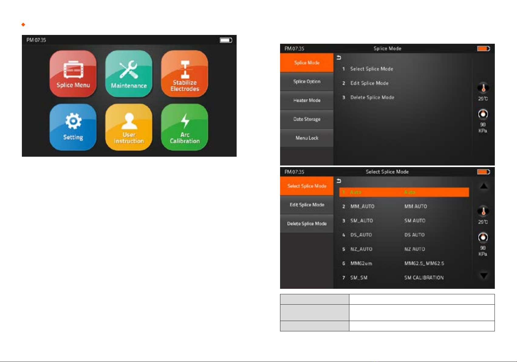
Splice Menu, Maintenance, Stabilize Electrodes, Setting, User Instruction, Arc Calibration
Atmospheric conditions such as temperature, humidity, and pressure are constantly changing, which
creates variability in the arc temperature. This splicer is equipped with temperature and pressure
sensors that are used in a constant feedback monitoring control system to regulate the arc power
at a constant level. However, changes in arc power due to electrode wear and glass adhesion cannot
be corrected automatically. Also, the center position of arc discharge sometimes shifts to the left or
to the right. In this case, the fiber splicing position has to be shifted in relation to the arc discharge
center. It is necessary to perform an arc power calibration to eliminate those problems.
Note : Performing [Arc calibration] function changes the arc power “Factor” value. The factor value is
used in the algorithm program for all splicing. The arc power value will not change in the splice modes.
[Arc Calibration]
In the event of sudden change in environmental conditions or after cleaning electrodes, the arc power
sometimes becomes unstable, resulting in higher splice loss. Especially when the splicer is moved
from lower altitudes to higher , it takes time for the arc power to stabilize. In this case, stabilizing
electrodes will expedite the process to set the arc power stable. If many tests are needed to get the
“Test ok” message appears in [Arc calibration], use this function as well.
[Stabilize Electrodes]
1) Splice Mode
[Splice Menu]
Select Splice Mode Factory Pre-set : 33ea
Edit Splice Mode User edit : 33ea
Custom build splice mode : 1ea
Delete Splice Mode -

- 10 - - 11 -
2) Splice Option
Auto Start
ON : Automatic splicing procedure
OFF : Maunal Splicing procedure
Pause 1
ON : Pause after the fiber gap position process
OFF : Proceeding without the pause
Pause 2
ON : Pause after camera focus & Axis alignment process
OFF : Proceeding without the pause
Realign After Pause 2
ON : Automatically proceed realignment
OFF : Proceeding without the pause
Ignore Splicing Error ‘splicng error’ message is not displayed
Fiber Image On Screen Select display structure for each splicing process
3) Heater Mode
Select Heater Mode Factory Pre-set : 9ea
Edit Heater Mode User edit : 9ea
Custom build splice mode : 1ea
Delete Heater Mode -
- 12 - - 13 -
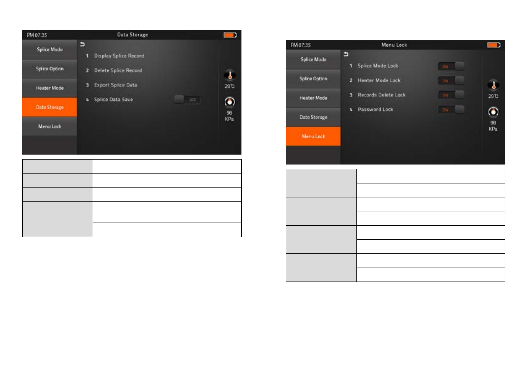
4) Data Storage
Display Splice Record Displaying your detailed splice record
Delete Splice Record -
Export Splice Data Downloading saved data (Splice record or Image)
Splice Data Save
ON : Automatic data save
* Image data is saved manually *
OFF : Do not save splice record
5) Menu Lock
Input password to access the sub-menus
Splice Mode Lock
ON : Disable ‘Splice mode’ edit
OFF : Ensable ‘Splice mode’ edit
Heater Mode Lock
ON : Disable ‘Heater mode’ edit
OFF : Enable ‘Heater mode’ edit
Recordes Delete Lock
ON : Disable ‘Record mode’ edit
OFF : Enable ‘Heater mode’ edit
Password Lock
ON : Disable to change the password
OFF : Enable to change the password
- 14 - - 15 -
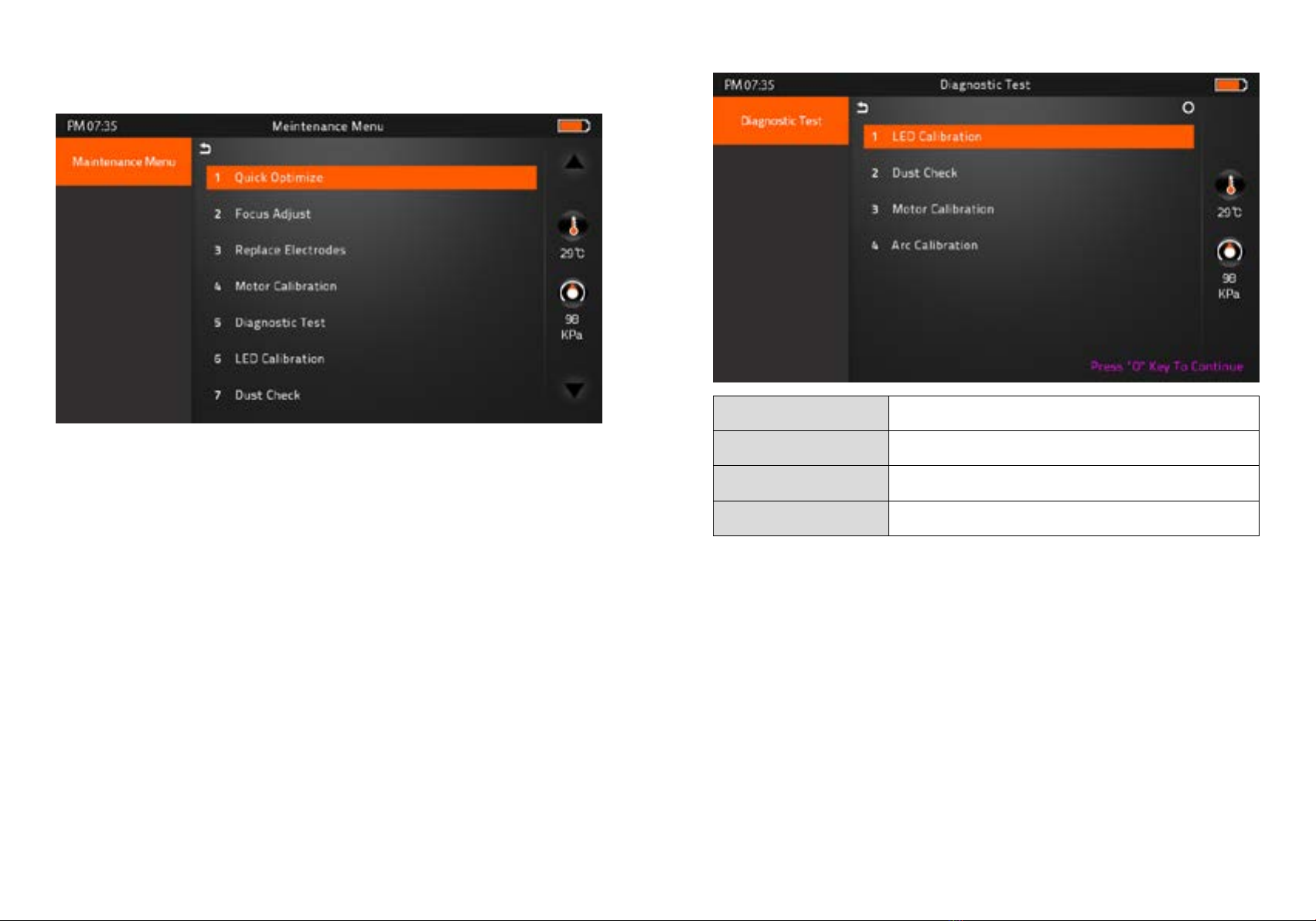
1) Maintenance Menu
▶ Quick Optimize
Quick & Easy overall maintenance
Automatic process ‘Lens focus+motor calibration+fiber training’
▶ Focus Adjust
Find the optimized posion for ‘Press, Focus & Align Motor’
▶ Replace Electrodes
Instruction on how to replace electrodes
FiberFox recommendation
It is highly recommended to change the electrodes every 3,000 splicing
▶ Motor Calibration
Automatically calibrates the speed of all six motors
[Maintenance] ▶ Diagnostic Test
LED Calibration Measures and adjusts the brightness of LED
Dust Check Dust checking process
Motor Calibration Automatically calibrates the motor speed
Arc Calibration Automatically calibrates the Arc power
▶ LED Calibration
Measures and adjusts the brightness of LED
▶ Dust Check
Detect dust&contaminant causing improper splicing
In order to find out optimized position for splicing, the splicer analyses the fiber images being
transmitted by the optical camera & LED inside but dust or contaminant on the camera, lenses,
LED may cause improper splicing result.
Therefore, the dust check process is recommended to proceed in case of frequent splicing fail
or high insertion loss.
- 16 - - 17 -
Automatic Fiber recognition program
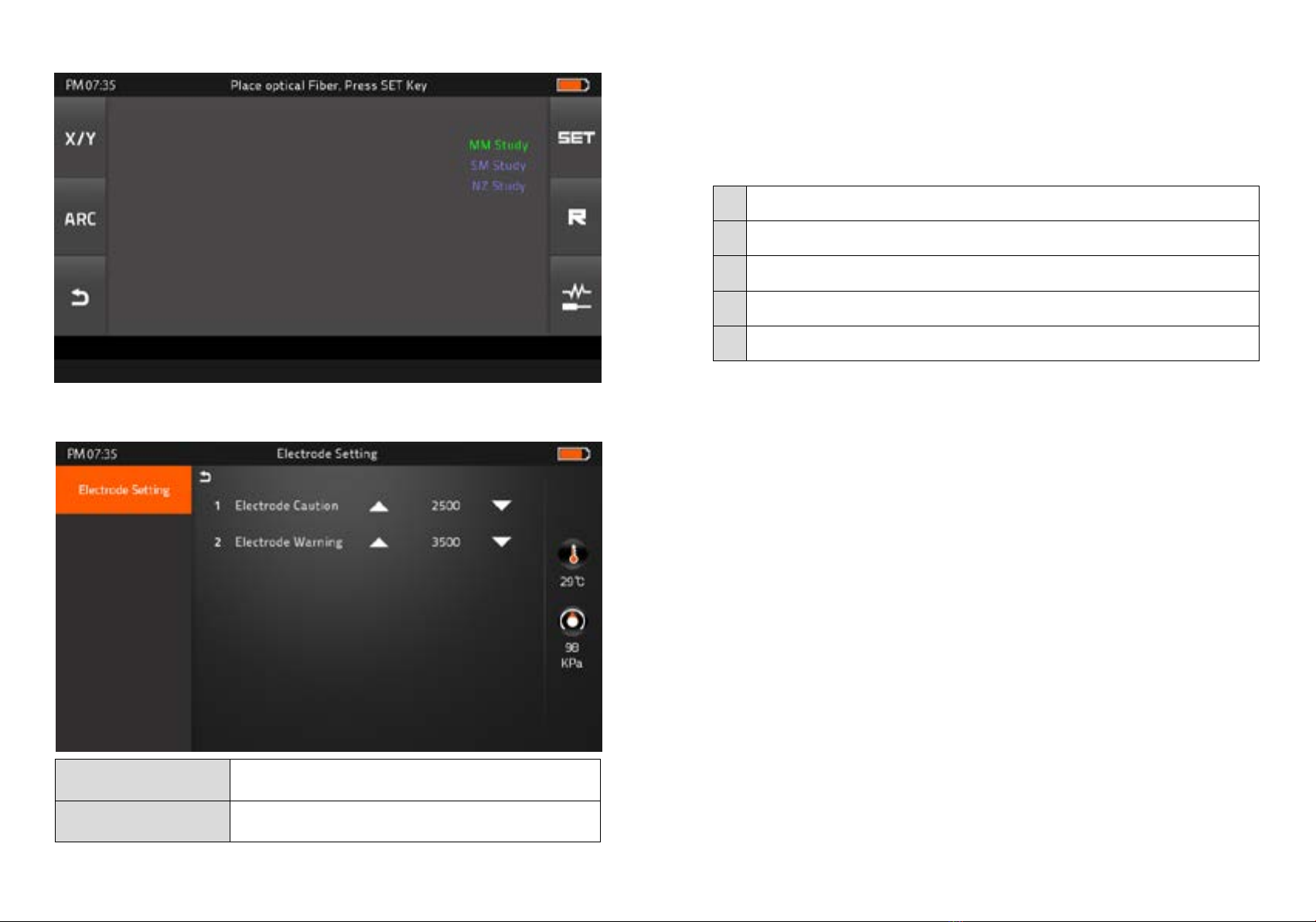
▶ Electrode Setting
▶ Fiber Training
Electrode Caution Caution alram will be displayed when it reachs the number of
splicing cycle you set
Electrode Warning Caution alram will be displayed when it reachs the number of
splicing cycle you set
▶ Motor Drive
It checks the operation status of 6 motors (L, R Press, X, Y Focus, X, Y Align).
▶ Update Software
Upgrade to the latest version.
Procedure
1Prepare the USB device.
2Download the latest version software to the USB.
3Link to the Splicer (Via link cable in the package).
4Press “O’ Button to proceed update.
5Device will be rebooted once it is done.

- 18 - - 19 -
[Setting]
1) System Setting
Buzzer ON : Sound on
OFF : Sound off
Temperature Unit
℃
: Celcisius
℉
: Fahrenheit
Automatic Heating ON : Auto start
OFF : Manual start
Monitor Position Front : Normal direction display
Rear : Opposite direction display
Dust Check ON : Check the dust density
OFF : Skip dust checking process
Password Lock ON : Password is required to operate the device
OFF : No passwerd is required
Pull Test ON : Automatic pull test processing after splicing
OFF : Skip pull test process
2) Language
Language Available
繁体中文 Việt
English ةيبرعلا
한글 Español
Русский Italiano
Deutsch Português
Français یسراف
ไทย
Set your own language.
Table of contents
Other FIBER FOX Network Hardware manuals

Popular Network Hardware manuals by other brands

Matrix Switch Corporation
Matrix Switch Corporation MSC-HD161DEL product manual

B&B Electronics
B&B Electronics ZXT9-IO-222R2 product manual

Yudor
Yudor YDS-16 user manual

D-Link
D-Link ShareCenter DNS-320L datasheet

Samsung
Samsung ES1642dc Hardware user manual

Honeywell Home
Honeywell Home LTEM-PV Installation and setup guide


