Fiber Instruments Sales ATLAS MINI OTDR User manual

ATLAS MINI OTDR User guide
1
FIS Atlas Mini Optical Time Domain
Reflectometer (OTDR)
This manual contains the operation and maintenance information of the FIS
Atlas Mini OTDR, as well as troubleshooting guide. Please read the manual
carefully before operating the Atlas Mini OTDR and follow the instructions.
The contents contained in this manual are subject to modification without prior
notice. If you have any questions, please call Fiber Instrument Sales Inc., phone:
1-800-500-0347 or 315-736-2206.
Fiber Instrument Sales Inc., 161 Clear Rd, Oriskany NY 13424.
ATLAS MINI OTDR
Power adapter
Input:AC 100V
~
240V,
50/60Hz@0.8A
Output:DC 9V,2A
Use the power adapter in strict accordance with the
device.
Battery:
Inside the instrument is dedicated lithium battery. To obtain full performance of the battery,
when using the instrument for the first time use the internal battery for power supply, after the
battery is exhausted then charge the battery. First charge time should not be less than 4 hours.
The charging temperature range of the battery in the machine is
When the ambient temperature is too high, please terminate the chargi
the instrument is idle for more than 2 months, it should be charged every two weeks to maintain
the battery power. Do not take out the battery without factory permission. Please do not put
the battery near a fire source or strong
temperature range of battery for long
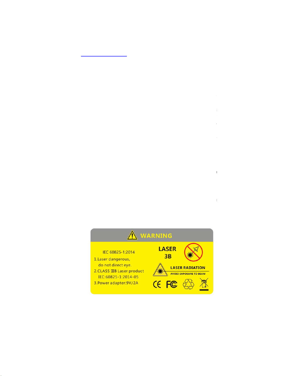
Laser safety instructions:
Laser safety level of this instrument is: CLASS
while in use, please pay attention and follow safety precautions.
When using this instrument avoid looking directly at the laser outlet or the end of the optical
fiber. When the instrument is active please cover
cap or insert dust cap on the laser light outlet. When the visual fault locator (VFL) of the
instrument is on, do not look directly at the output port of the red light source or at the end of
the optical fiber
connected to the red light output end, it can cause damage to the human eyes.
MINI OTDR
2
Security Warning
50/60Hz@0.8A
Use the power adapter in strict accordance with the
specifications, or it may cause damage to the
Inside the instrument is dedicated lithium battery. To obtain full performance of the battery,
when using the instrument for the first time use the internal battery for power supply, after the
battery is exhausted then charge the battery. First charge time should not be less than 4 hours.
The charging temperature range of the battery in the machine is
-10
℃
(14 F)to 50
When the ambient temperature is too high, please terminate the chargi
ng for your safety. When
the instrument is idle for more than 2 months, it should be charged every two weeks to maintain
the battery power. Do not take out the battery without factory permission. Please do not put
the battery near a fire source or strong
heat. Do not open or damage the battery. The
temperature range of battery for long
-term storage should be -20
℃
(-4 F)to 45
℃
(113 F).
Laser safety level of this instrument is: CLASS
Ⅲ
B, the laser can be harmful to human body
while in use, please pay attention and follow safety precautions.
When using this instrument avoid looking directly at the laser outlet or the end of the optical
fiber. When the instrument is active please cover
opposite end of connector/ferrule with a dust
cap or insert dust cap on the laser light outlet. When the visual fault locator (VFL) of the
instrument is on, do not look directly at the output port of the red light source or at the end of
connected to the red light output end, it can cause damage to the human eyes.
MINI OTDR
User guide
specifications, or it may cause damage to the
Inside the instrument is dedicated lithium battery. To obtain full performance of the battery,
when using the instrument for the first time use the internal battery for power supply, after the
battery is exhausted then charge the battery. First charge time should not be less than 4 hours.
(14 F)to 50
℃
(122 F).
ng for your safety. When
the instrument is idle for more than 2 months, it should be charged every two weeks to maintain
the battery power. Do not take out the battery without factory permission. Please do not put
heat. Do not open or damage the battery. The
(113 F).
B, the laser can be harmful to human body
When using this instrument avoid looking directly at the laser outlet or the end of the optical
opposite end of connector/ferrule with a dust
cap or insert dust cap on the laser light outlet. When the visual fault locator (VFL) of the
instrument is on, do not look directly at the output port of the red light source or at the end of
connected to the red light output end, it can cause damage to the human eyes.

User guide
3
ATLAS MINI OTDR
Physical Features:
1)Wavelength: Single mode:1310/1550nm
2)Measuring range: Min 100m – Max 90km
3)Touch screen or Hard Key Functions
4)OTDR data format: SOR format
5)Onboard Features: Power meter, Light source, VFL, OTDR, Graphical Event Map Display, Fiber Inspection,
and Network Cable Test.
6)Keyboard input, edit save file name and line number
7)Support user upgrade
8)The 4.3-inch TFT screen, 800 x 480 pixels, display screen is optimized for outdoor sunlight.
9)3.7v /5200mAh lithium batteries are used, which can be fully charged for more than 8 hours operation.
10) Size 6.9” x 4.1” x 1.8”, Weight: 1.25lbs (20 Oz.) (including battery)
11) Units of measurement: Kilometers, Kilofeet, Miles
12) Working temperature:-10 to+55°C (14 to 131F), storage temperature: -20~+80°C (-4 to 176F)
Technical Specifications:
Measuring range 100m, 500m, 2km, 5km, 10km, 20km, 40km, 60km, 100km
Sampling resolution Minimum: 0.2m
The sampling point 64,000 point
linearity ≤0.05dB/dB
Loss threshold 0.01dB
Loss resolution 0.001dB
Range resolution 0.01m
Range accuracy ±(0.5m+Range×3×10⁻⁵+Sampling resolution) (Excluding refractive index error)
Memory >80,000
VFL 10mW,CW/2Hz
Data interface 2.0 USB(Type A×1,Micro usb×1), SD card
Screen 4.3-inch TFT-LCD (Standard distribution capacity touch screen)
Battery 3.7V/5200mAh
Temperature Working temperature:-10C~+55
℃
Storage temperature:-20
℃
~+80
℃
Humidity ≤95%(No condensation)
Size/Weight 6.9” x 4.1” x 1.8” / 1.25 lbs. 20 Oz.(Contain the battery)
Attachment Power adapter, lithium battery, FC adaptor, USB cable, quick guide, portable package
OPM Type A:-10dBm~-70dBm;Type B:+26dBm~-50dBm
Laser source The output power:-4~-10dBm±2dB,Modulation Frequency: CW/270Hz/1KHz/2KHz
Network Cable test Support network wire sequence testing and wire alignment

ATLAS MINI OTDR User guide
4
No Name Describe
I Optical interface OTDR, Visual Fault Locator, Power meter, Light source
II Electrical interface Charging port, Micro USB, USB 2.0
(
Type A
)
,SD card, RJ45, LED
III Keys
【
M
】
:Manual testing
【
A
】
:Auto testing
OK(select): Directional navigation keys, Escape(ESC),
SETUP: Enter the setting test parameters
User guide

ATLAS MINI OTDR
User guide
5
1. System settings:
Press [Setting] icon in the interface of the main menu to enter the system settings menu, and the
following settings can be edited:
Language selection
Backlight adjustment
Automatic shutdown
Date Settings
Time Setting
Touch screen calibrate
Upgrades
System information
(
Series no, Instrument model, Hardware and software version number
)
User guide
6
ATLAS MINI OTDR
2. OTDR Function Application
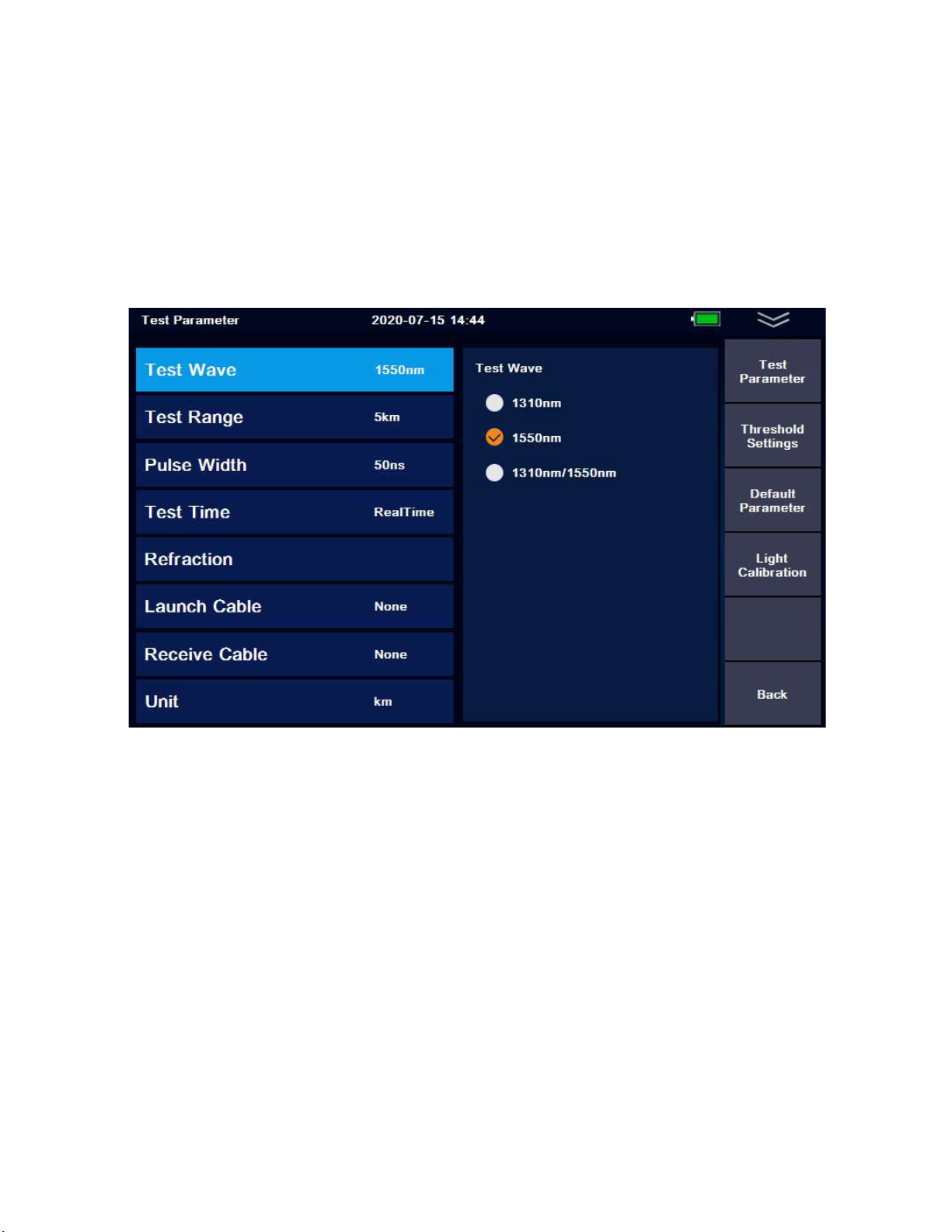
2.1 Setting
Under the main interface of the OTDR, press the [Parameter Settings] button to quickly enter the
Test Parameter menu:
“
Test parameter
”
Menu
2.1.1 Test Parameter
Wavelength: 1310nm, 1550nm.
Measuring range:
-AUTO mode: The device will automatically set the most appropriate parameters for the
current measurement including the measurement range and pulse width. Auto selected
values cannot be modified in this setting.
-Manual mode: The range and pulse width can both be set manually.
Pulse Width: Pulse width refers to the time width of emitting laser signal during measurement.
The wider the pulse width is, the stronger the optical power injected into the fiber, the
stronger the backscattering signal of the fiber, and the farther the OTDR can effectively detect,
but a wide pulse width will cause saturation of the initial reflection signal, resulting in larger
deadzone. Therefore, the selection of pulse width is related to the measurement of fiber
length. The longer the length is, the wider the pulse width. It can not be modified in the
automatic measurement mode, which defaults to "automatic configuration".

ATLAS MINI OTDR User guide
7
Measuring time: In the mean measurement mode, the longer the detection time is, the better
the signal-to-noise ratio is improved, and technician receives more accurate the test results.
The user should reasonably select the detection time, which is proportional to the dynamic
measurement.
Resolution: High resolution will have more sampling points and higher accuracy, but it will also
increase time of test due to amount of data collected.
Refractive index: Is the essential characteristics of optical fiber, different manufacturers of
optical fiber have slightly different refractive index which is the key parameter to calculate the
distance, this value cannot be arbitrarily set.
Unit: Kilometer/Kilofeet/Miles.
OTDR will automatically select the most appropriate reference pulse width when manual
measurement range is set in automatic mode.
The range and pulse width can be adjusted manually in manual mode. The following list is for
reference only:
Range
Pulse
Width
100m 500m 2km 5km 10km 20km 40km 60km 100km
5ns √ √ √ △ △ △ △ △ △
10ns √ √ √ √ △ △ △ △ △
20ns √ √ √ √ √ △ △ △ △
50ns √ √ √ √ √ √ △ △ △
100ns △ √ √ √ √ √ △ △ △
200ns △ △ √ √ √ √ √ △ △
500ns △ △ △ √ √ √ √ √ √
1us △ △ △ △ √ √ √ √ √
2us △ △ △ △ △ √ √ √ √
5us △ △ △ △ △ △ √ √ √
10us △ △ △ △ △ △ △ √ √

User guide
8
ATLAS MINI OTDR
2.1.2 OTDR Parameter Settings
Various event measurement thresholds, including attenuation/reflection/slope/optical fiber end
refractive index and scattering coefficient settings.
The refractive index is selected by the user and changing the refractive index setting will change
the ranging result. The refractive index is provided by the fiber optic cable or fiber optic
manufacturer. Users are advised to calibrate the group refractive index with a known length of
fiber and remember it.
The scattering coefficient is usually obtained from the fiber optic cable manufacturer.
2.1.3 Restore the default
Restore to factory default Settings.
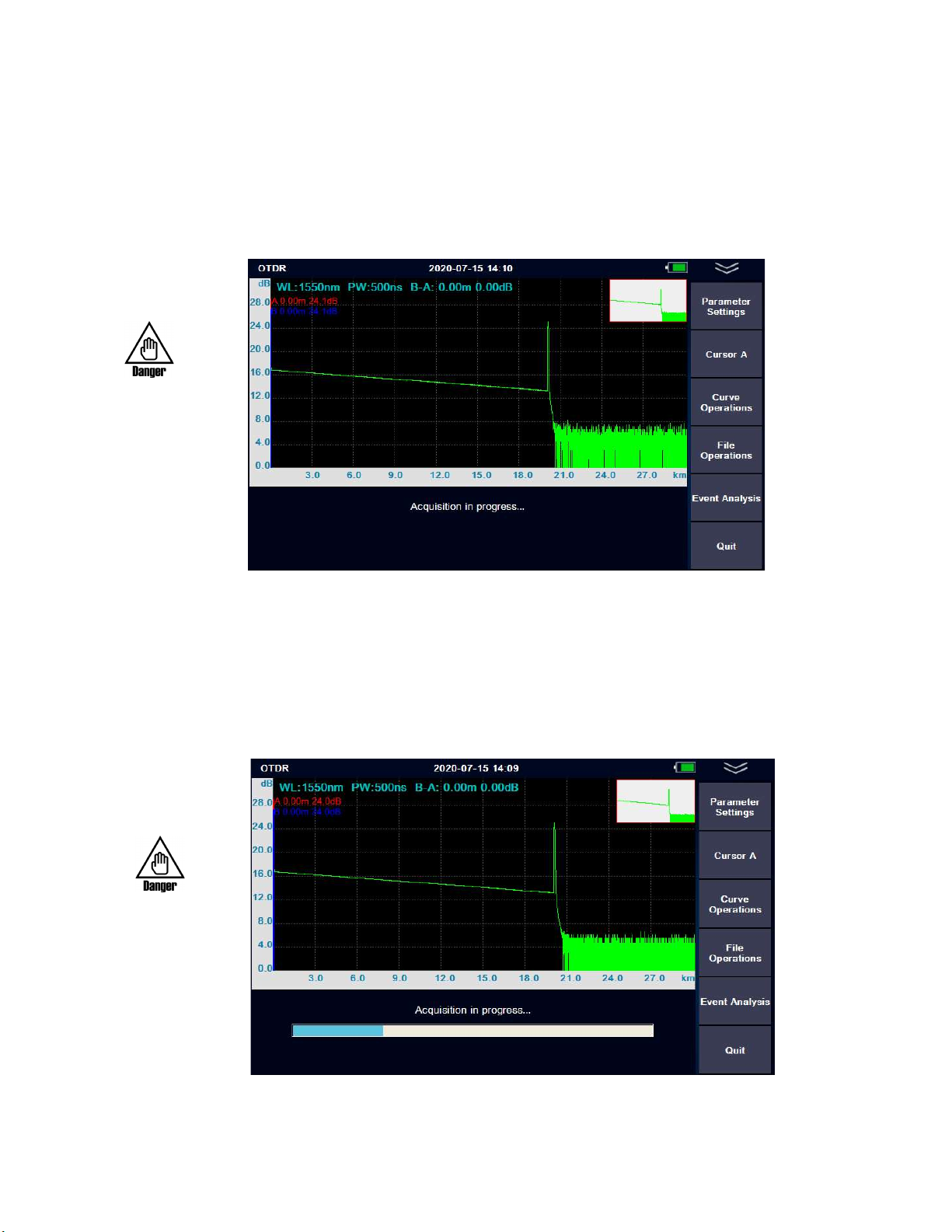
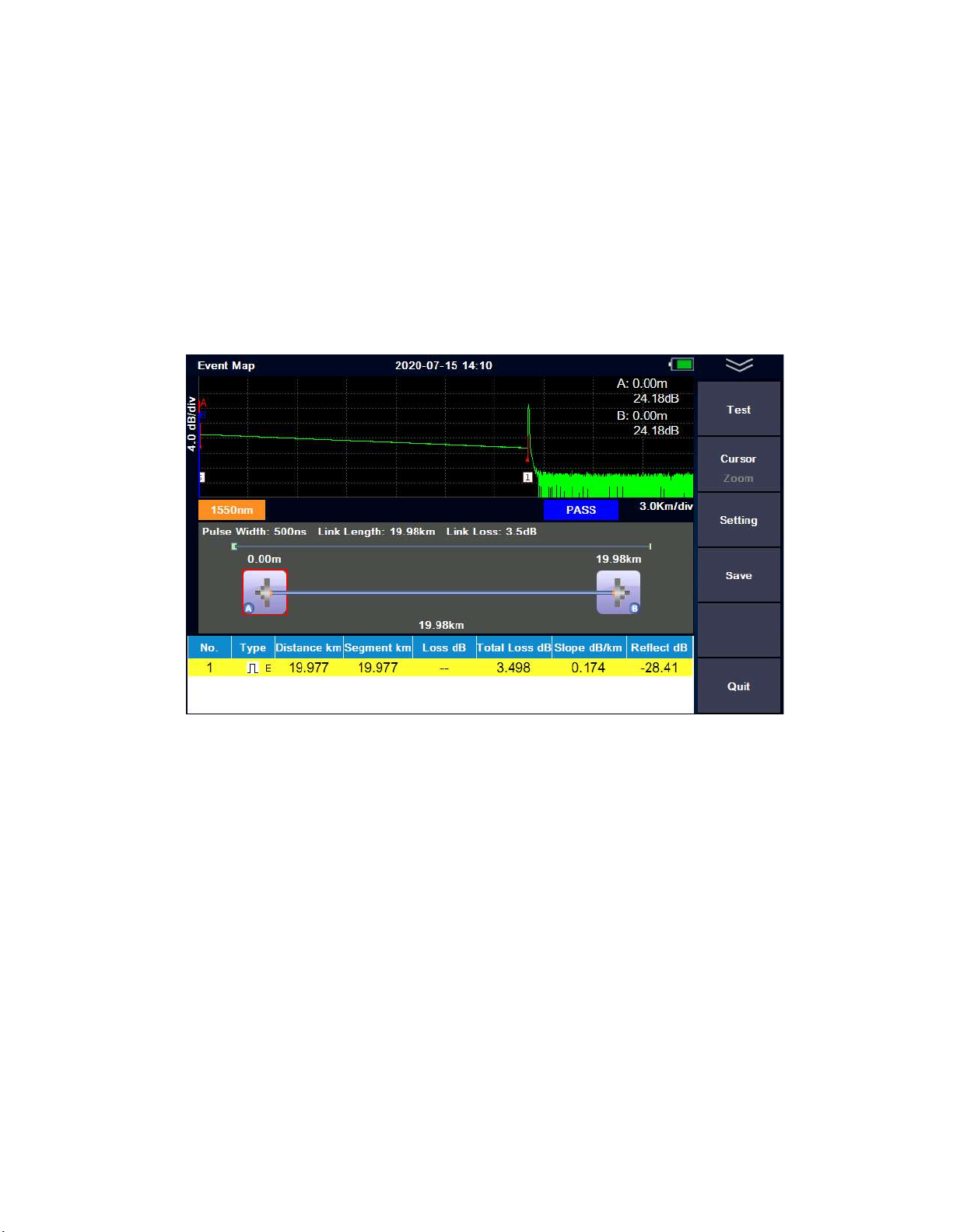
2.2 OTDR
On the OTDR panel is where test data will be displayed on the graph and event table below it. The
following is the meaning of each label in the OTDR interface:
Cursor A
Allows the user to have control of the “A” Cursor. Selecting it a second time allows the user
to have control of cursor “B”
Curve /Trace operation
Trace manipulation sub-menu, including: cursor, zoom and trace translation.
File operations
File operation submenu, including: open file, save file, multi trace operation and save file.
Event analysis
Trace analysis sub-menu, including: cursor, trace zoom, event list view, add and delete events
More (multi-trace operation and event analysis function description)
-Add event : The event list is added accordingly.
-Delete events: The event list will delete the event accordingly.
-Clear choice: When multi-trace line loads, clear the selected trace and event list.
-Remove other: When multi-trace lines are loaded, clear the list of traces and events other than
the selected trace.
-Clear all: Clear all measurement traces and event lists in the current measurement interface
9
ATLAS MINI OTDR User guide
REAL TIME MODE:
Parameter settings->Test time->Average mode press
【REAL/AVG 】
key enter the real-
time measurement mode. The current circuit is measured in real time and the
measurement parameters cannot be modified in the measurement mode. If the
parameters need to be modified, the test needs to be stopped first. Event analysis will not
be conducted during the real-time test, and event analysis will only be conducted after the test
is stopped.
REAL TIME MODE
Average mode
Parameter settings/Test time/XX seconds Press
【
REAL/AVG
】
key enter the real-time measurement
mode, The trace (or sometimes referred to as “Curve”) consisting of the average values measured
over a period of time can be displayed. The length of time can be edited in the "measurement
time" option in [SETUP].
Average mode
ATLAS MINI OTDR
User guide
10
When the measurement is finished, the measurement result will be automatically saved.
Under no circumstances shall the optical interface and the end of the tail fiber connected to the
optical interface be directed to the eye of the operator or other person. Otherwise, the eyesight
of the irradiated person can be damaged.
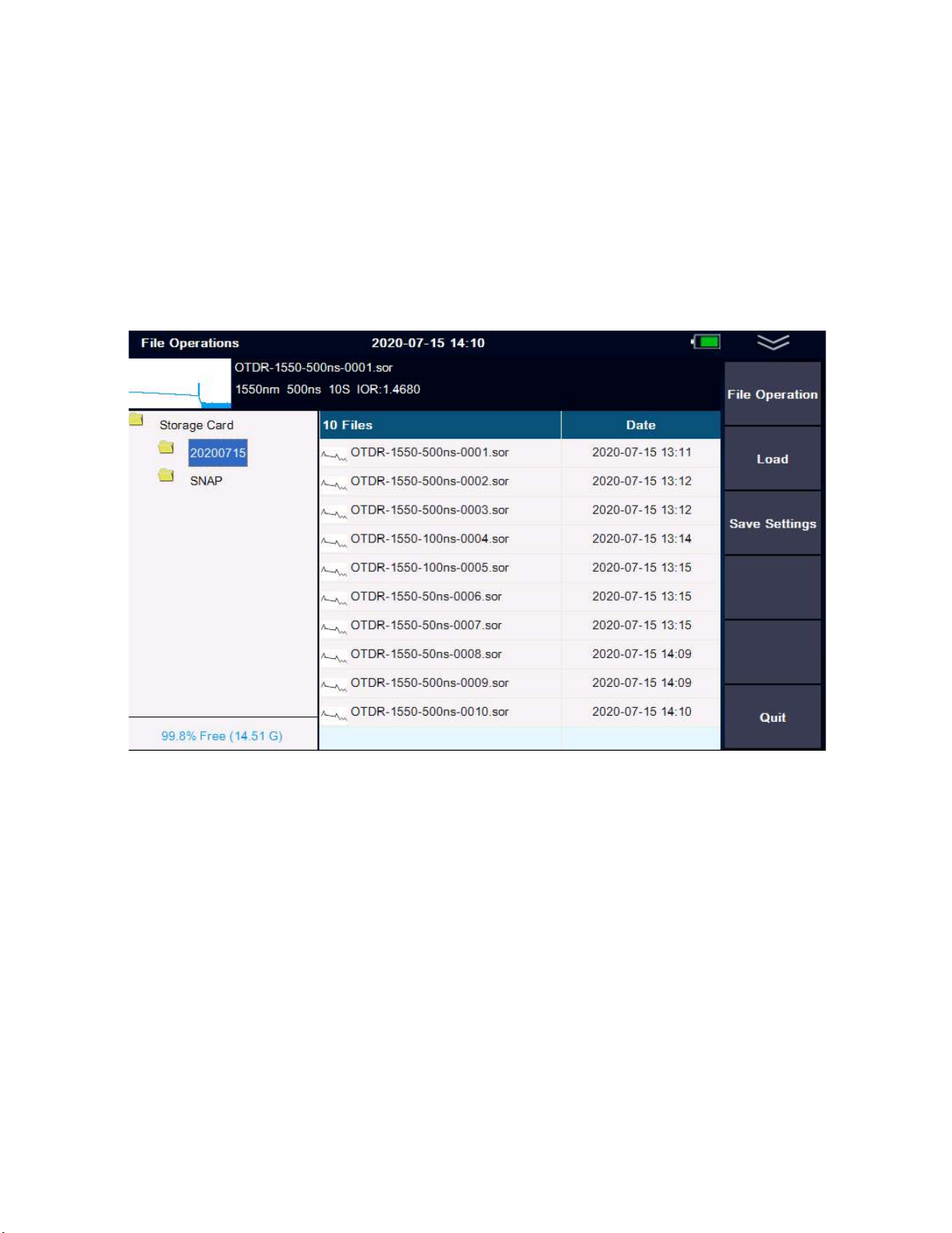
2.3 File storage
Press [FILE] to view and edit stored files
File operation
The menu provides a complete file storage call out function. The results of each measurement are
automatically saved to internal storage (configurable) and marked with time, date, serial number
and other information for easy reference. Users can name, number, comment on each
measurement trace, and generate complete reports through the reporting attached software
which is included on the SD memory card to be used on a PC. For more information on the PC
(computer) software, go to page 14.
User guide
11
ATLAS MINI OTDR
2.4 Graphical Event Map
Graphical event maps can be used to assist in viewing and troubleshooting fiber links for new technicians.
The event map translates the connection of the whole fiber link directly into the physical schematic
diagram, such as fusion splice connection, connector pair connection, optical splitter, launch and receive
fibers and macro-bends.
Some analysis parameters need to be set before using graphical event map measurements (the OTDR has
default classical values, if the user is not familiar with the link analysis parameters, it is recommended to
use the default values directly).
Event map
2.4.1 Pass/Fail Threshold
The pass/fail threshold parameter is used to judge whether the splice junction and connector pair connection
point are within the qualified range or exceed the threshold parameter. The schematic diagram shows red, is
values exceed threshold parameter, or green if the values are acceptable within parameters.

ATLAS MINI OTDR
User guide
12
The threshold parameter
2.4.2 Splitter loss Settings
In a PON network there is usually 1 x N splitters, but the loss of each splitter may be different. Therefore it is
necessary to limit the loss value of the splitter. If the value range is set incorrectly, the accuracy of the event
map will be affected.
Splitter loss Settings

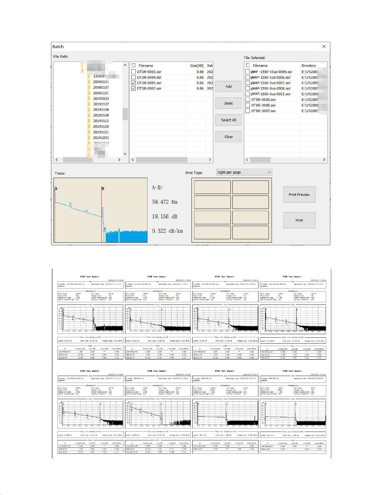
If the user needs to carry out multi
operation, the measurement data stored in the device after measurement can also be printed by
the software.
(For detailed operation of
desktop
desktop computer software)
Note: the software installation package and software operation instructions are stored in the SD
card of the device. Relevant files can be imported into the computer through the MINI USB cable.
Batch printing:
You can set the A/B cursor of each pict
the report.A/B cursor is located at the start and end events by default.
MINI OTDR
13
2.5 Computer softwar
ATLAS MINI OTDR
2.5 Computer software
e
If the user needs to carry out multi
-trace comparison, other furth
er analysis functions or remote
operation, the measurement data stored in the device after measurement can also be printed by
desktop
computer software, please refer to the operation manual of
Note: the software installation package and software operation instructions are stored in the SD
card of the device. Relevant files can be imported into the computer through the MINI USB cable.
You can set the A/B cursor of each pict
ure arbitrarily,
A/B cursor information will be printed on
the report.A/B cursor is located at the start and end events by default.
MINI OTDR
User guide
er analysis functions or remote
operation, the measurement data stored in the device after measurement can also be printed by
computer software, please refer to the operation manual of
Note: the software installation package and software operation instructions are stored in the SD
card of the device. Relevant files can be imported into the computer through the MINI USB cable.
A/B cursor information will be printed on
ATLAS MINI OTDR
User guide
14

User guide
15
ATLAS MINI OTDR
3. Other Features:
3.1 Visual Fault Locator (VFL)
VFL module(650nm)
VFL module
VFL module has two emission modes:
CW MODE: In this mode a continuous stream of visible red light is emitted.
2Hz MODE: In this mode, visible red light flashes at a frequency of 2Hz.
Press [Shutdown], [Quit] or [ESC] to turn off the VFL
When using the VFL module, do not aim the emitting laser at person’s eyes, it may cause
irreversible damage.
User guide
16
ATLAS MINI OTDR
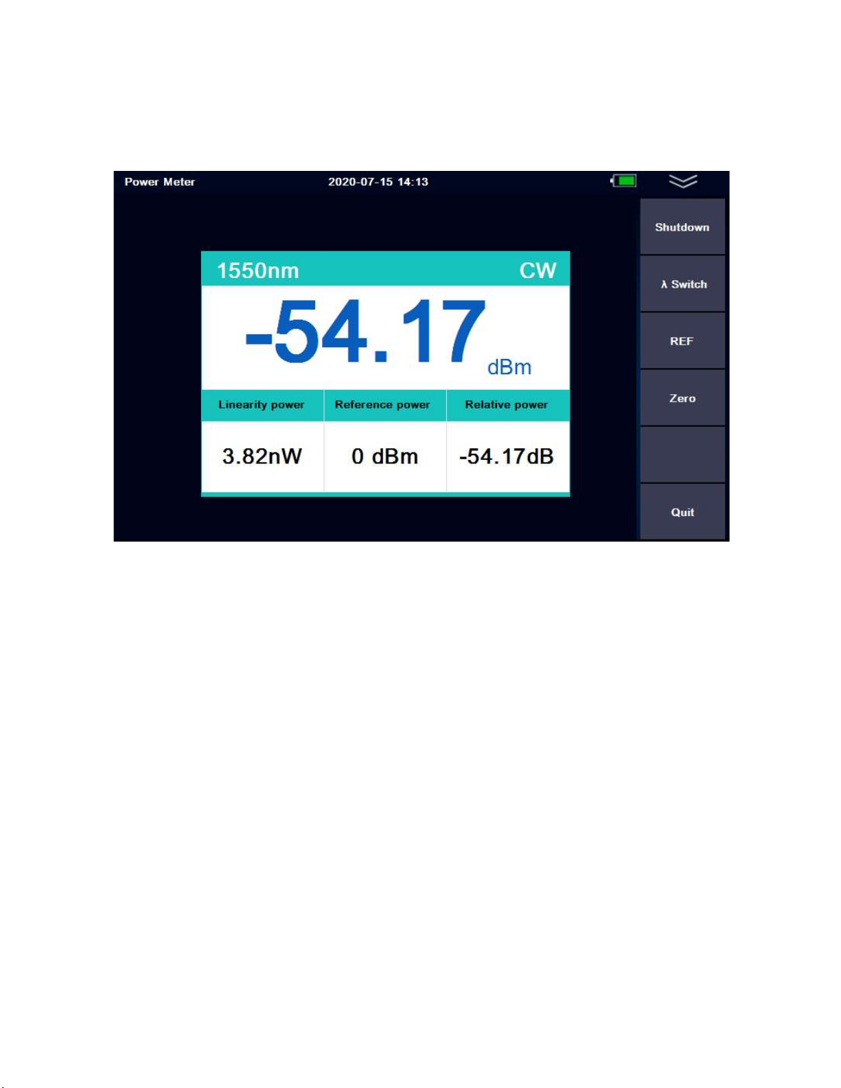
3.2 Optical Power Meter (OPM)
Unit: dB, dBm, uW or mW
OPM module
Start/Shutdown
Turn on and off optical power meter function.
Wavelength switching:
Press the "ʎ switch" TAB to switch the current wavelength.
Set as the reference value:
Press the "REF" TAB to set the current value to the optical power meter reference.
Clear zero:
Press the “Zero” TAB to restore the reference value set.
Frequency:
The power meter has a frequency identification function and can identify 270Hz / 1kHz / 2kHz.

User guide
17
ATLAS MINI OTDR
3.3 Laser source module
The light source module and OTDR use the same optical port.
.
Light source module
Start/Shutdown
Turn on or Turn off the light source module.
Wavelength Switch
Press“ʎ Switch”to change wavelength.
Frequency switching
Press the "frequency switch" TAB to switch the output frequency of the laser: Continuous Wave
(CW)/270Hz/1kHz/2kHz
Description of function and index of light source
1
)
The output power of the laser:-4dBm~-10dBm ± 2dB
2
)
Optimize laser stability time: 3 minutes
User guide
18
ATLAS MINI OTDR
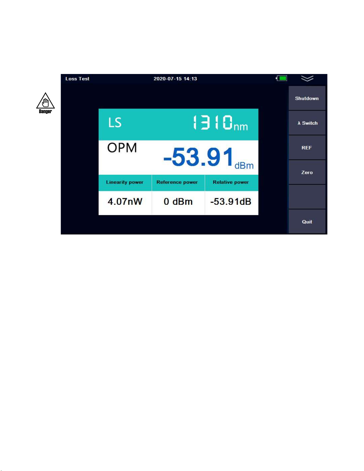
3.4 Optical Loss Test Set
When the unit is installed with both the stable light source and the optical power meter, the loss
test set module will be automatically activated.
Optical Loss Test Set Module Interface
Start/stop: Turn on and off the loss test set module.
ʎ Switch: Press the "ʎ Switch" TAB to switch the current wavelength.
REF: Set the reference value. Use this to get ready to test for dB loss
Zero: Restore the set reference value. Use this to reset your reference value for a new test
3.5 LED Flashlight
The instrument is equipped with a LED, which is convenient for users to operate in dark areas.
Operation method 1: In the start-up state, short press the "power key", you can turn the flashlight
on and off.
Operation method 2: In the startup state, there is a “LED” switch button in the pull-down dialog
box in the operation menu in the upper right corner to activate the flashlight switch.
ATLAS MINI OTDR
User guide
19
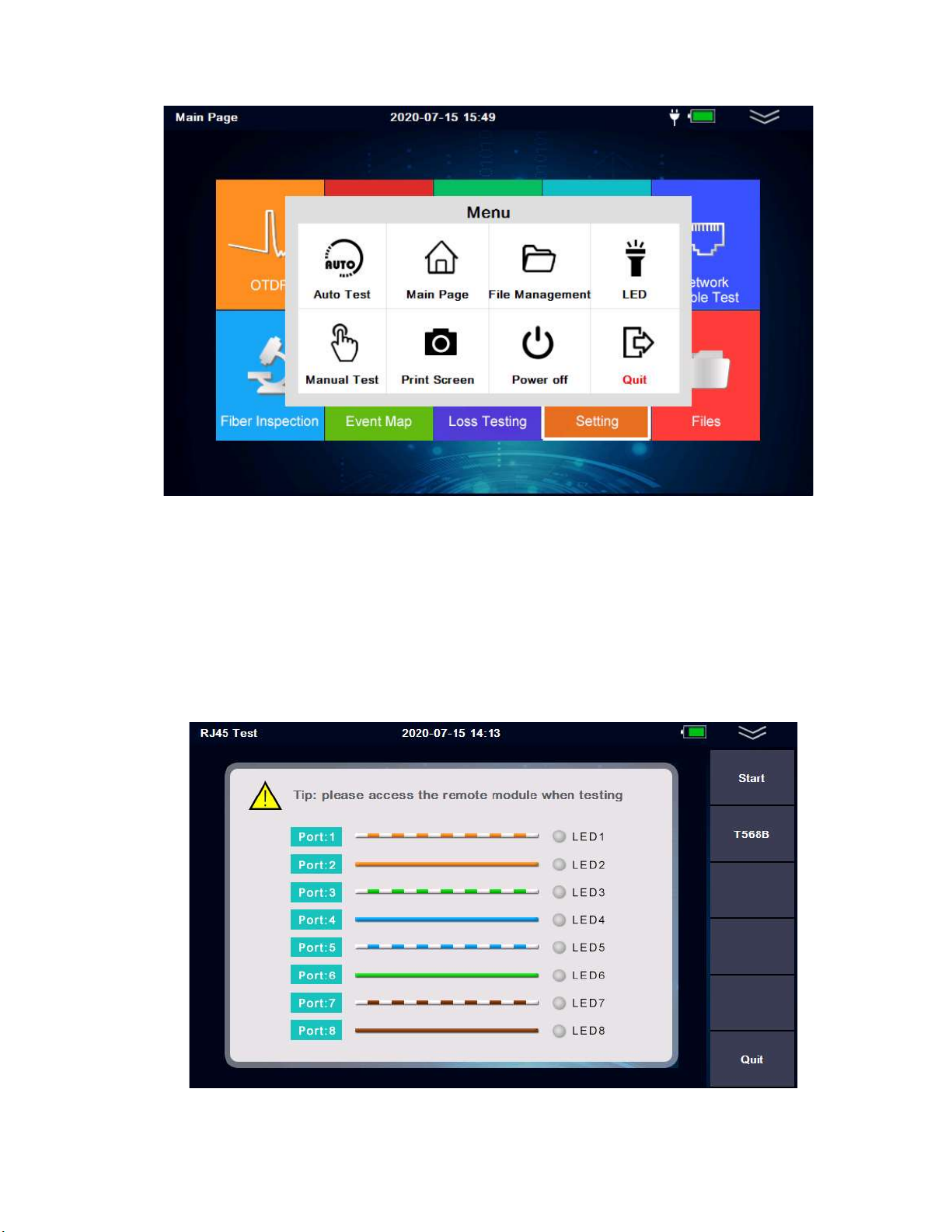
MENU
3.6 Network Cable Test module
This module is used for the line sequence test and line alignment test of RJ45 standard network
cable. It can check whether the network cable is connected and whether the line sequence is
correct, which is convenient for terminal installation and maintenance technicians to analyze the
network link condition. The module must match a cable test terminal. There are two test modes:
T568A and T568B
Network Cable Test
User guide
20
ATLAS MINI OTDR
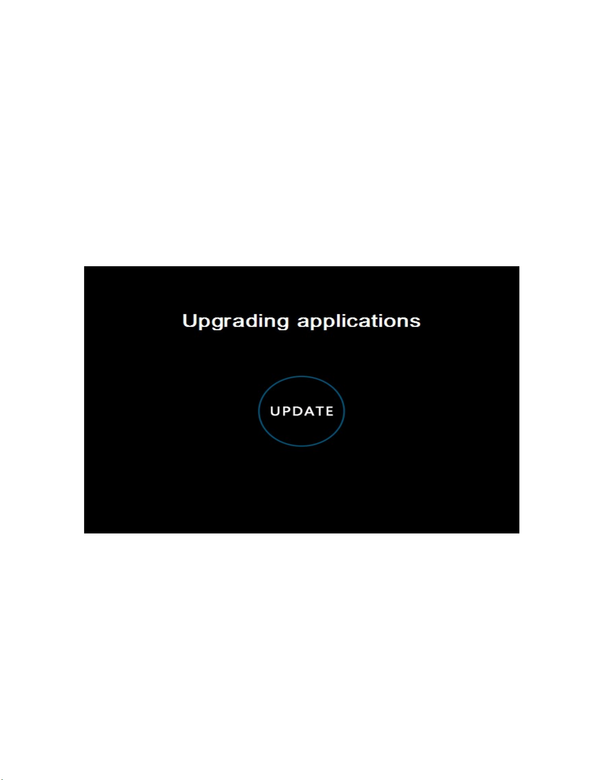
4. Software upgrade
Firmware updates are made by plugging a USB drive into the USB port (the upgrade software
must be in the root directory).
Steps:
1
)
Place the software upgrade package in the root directory of your USB flash drive.
2
)
Turn on the instrument and insert the USB disk into the USB port of the instrument.
3
)
The main interface-->System Settings-->Software upgrade
4
)
After entering the upgrade interface, the upgrade will be completed automatically
**Important Note**: during the upgrade, please do not turn off the power or unplug the USB
drive. These illegal operations may cause system software damage and the OTDR will not start
normally. Once this happens, user will have to contact FIS for system repair.
Table of contents
Other Fiber Instruments Sales Test Equipment manuals


