FIBER SENSYS SecurLAN Installation and operating instructions

Application Note
SecurLAN®
Optical Cutoff Switch
Installation
Rev. A
SUMMARY
Connected to the SecurLAN system, the Optical Cutoff Switch op-
tion enables the system or the operator to take protective action in
the event an intrusion attempt is detected at the physical level of a
network’s infrastructure. Unlike older versions of the hardware, the
new Optical Cutoff Switch is not only capable of disrupting the ow of
data through the compromised cable, but certain congurations of the
switch are also capable of re-routing data to a secured cable.
IntroductIon
The SecurLAN®Optical Cutoff Switch is an option that enables the Secur-
LAN system to take protective action in the event an intrusion attempt is
detected at a protected network data cable (a network conguration known
as a Protected Distribution System or PDS). Depending upon its congu-
ration, the Optical Cutoff Switch is able to either halt the ow of data or
re-route it to another cable.
Figure 1 - The SecurLAN System Block Diagram

2
SecurLAN®Optical Cutoff Switch Installation
Application Note
Compatible connector types
The Optical Cutoff Switch connects to the system through the Output Relay Module
(ORM). Alternatively, the Optical Cutoff Switch is capable of connecting to the Base
Unit Controller directly provided the Base Unit Controller’s port is congured as a “Gen-
eral Purpose I/O Port.”
descrIptIon
The Optical Cutoff Switch is compatible with either 1310/1550 nm single-mode or
850/1300 nm multimode optical networks, depending upon which option is ordered.
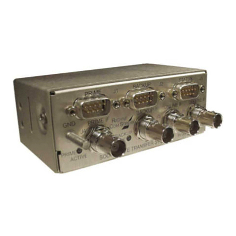
Figure 2 - The Optical Cutoff Switch
The Optical Cutoff Switch has 3 general congurations:
• A 1x1 switch with one pair of direct input-to-output ports
• A 2x2 switch with a dual pair of direct input-to-output ports
• A 1x3 switch with an input port connecting to one of 3 output positions (“Port A,”
“Port B,”, or “Off”)
Figure 3 - Optical Cutoff Switch Conguration Options
2x2 S
WITCH
1x3 S
WITCH
1x1 S
WITCH
SecurLAN
®
Optical
Cutoff Switch
1x1 Data Switch
Data
A
B
SecurLAN
®
Optical
Cutoff Switch
2x2 Data Switch
Data
Data
A
B
A
B
SecurLAN
®
Optical
Cutoff Switch
1x3 Data Switch
Data
Data
A
B
off
in
Each optical port is made to accept input from SC or ST-type connectors - specify con-
nector type when ordering.
Optical Cutoff Switch
congurations

SecurLAN®Optical Cutoff Switch Installation
3
Application Note
A tri-color LED next to each optical port indicates the status of data owing through the
port:
Table 1 - Status LED States
The Optical Cutoff Switch comes with a front panel designed to facilitate mounting
in our 4 U, 19-inch instrument rack, RK-210. The front panel measures 1.78 inches
across and 6.82 inches tall. Two captive screws in the upper and lower left-hand cor-
ners allow the user to mount the Optical Cutoff Switch in the instrument rack.
A 5-pin terminal block mounted on the rear panel of the Optical Cutoff Switch has con-
nection points for external power as well as input from the SecurLAN system.
Table 2 - Optical Cutoff Switch Rear Panel Pinout
Input power to the Optical Cutoff Switch is limited to 6-15 VDC, 10 mA. If input voltage
drops below 6 VDC, the normally-closed Optical Cutoff Switch opens, disrupting the
optical data ow. Input voltage over the 15 volt limit damages the switch.
Note: If the 15 volt maximum limit is exceeded, the status LEDs blink rapidly to warn
the user.
operatIng prIncIples
The Optical Cutoff Switch is designed to pass optical data from the input connector to
the output connector on its front panel. Inside the Optical Cutoff Switch, the optical path
from the input to the output connector is interrupted only by an internal optical switch.
When +6-15 VDC power is applied to the Optical Cutoff Switch, the internal switch is in
the “closed circuit” position and data is allowed to pass through uninhibited.
Status LEDs
Rear panel pinout
Input voltage limit
LED Color Indication
Green Data is transmitting through the
primary port OK
Red No data is transmitting
Amber Data is transmitting through the
alternate port OK
Pin Description
1 +6 - 15 VDC input power
2Ground
3 Input 1 (not used)
4Input 2 (1 x 3 conguration only)
5 Input 3

4
SecurLAN®Optical Cutoff Switch Installation
Application Note
Operating the switch
Figure 2 - Inside the Optical Cutoff Switch
With the Optical Cutoff Switch connected properly to the SecurLAN system, an alarm
condition causes a relay to close in either the ORM or the Base Unit Controller, plac-
ing a ground on the Input pin on the rear panel of the Optical Cutoff Switch. Placing
a ground on this pin shunts power away from the internal optical switch, causing the
internal switch to open and halt the ow of data.
When powered, the Optical Cutoff Switch operates according to the description in Table
3.
Table 3 - Normal Operating Positions of the Optical Cutoff Switch
Normal operating states
LED Color Normal (Powered) State Unpowered State
1 x 1 Closed Open
2 x 2 Both switches closed Both switches open
1 x 3 Port A Off

SecurLAN®Optical Cutoff Switch Installation
5
Application Note
operatIon
This section outlines steps for connecting and operating the Optical Cutoff Switch with
the SecurLAN system.
connectIng to the output relay Module (orM)
To connect the Optical Cutoff Switch to the ORM:
1. Connect +6-15 VDC from an external power supply to Pin 1 of the Optical Cutoff
Switch.
2. Connect the negative lead of the power supply to Pin 2 of the Optical Cutoff
Switch.
3. Select a relay on the ORM to use for activating the Optical Cutoff Switch. Keep-
ing track of the relay number, connect the common pin (“COM”) of the ORM
relay to Pin 2 (ground) of the Optical Cutoff Switch.
4. Connect the normally-open pin of the ORM to Pin 5 (“Input 3”) of the Optical
Cutoff Switch.
Figure 3 - Wiring up the Optical Cutoff Switch
Optical Cutoff Switch
connection points

6
SecurLAN®Optical Cutoff Switch Installation
Application Note
5. For 1x3 Optical Cutoff Switches, repeat Steps 3 and 4, connecting a second
relay on the ORM to Pin 4 of the Optical Cutoff Switch (“Input 2”). This second
relay is then used to move the internal switch between Port A, Port B, and the
Off position in accordance with Table 4.
Table 4 - Optical Cutoff Switch Input Truth Table
The maximum wiring distance between the power supply and the Optical Cutoff Switch
is 15 meters (50 feet) assuming 22 AWG, 8 conductor, shielded cable is used. Once
completed, the Optical Cutoff Switch is connected to the system as shown in Figure 4.
Maximum wiring distance
Input 3 Input 2 Switch State
1x1
High (disconnected) Closed
Ground (disconnected) Open
2x2
High (disconnected) Closed (both)
Ground (disconnected) Open (both)
1x3
High High Port A
Ground High Port B
High Ground Port A
Ground Ground Off

SecurLAN®Optical Cutoff Switch Installation
7
Application Note
Figure 4 - Optical Cutoff Switch Wiring Diagram

SecurLAN®Optical Cutoff Switch Installation
8
Application Note
For more information on installing and using the Optical Cutoff Switch option with
the SecurLAN system, please contact Fiber SenSys’ sales or technical support
team directly at +1-503-692-4430 or by email at info@bersensys.com.
2925 NW Aloclek Drive, Suite 130
Hillsboro, OR USA 97124
Phone: +1-503-692-4430
Fax: +1-503-692-4410
www.bersensys.com
Table of contents
