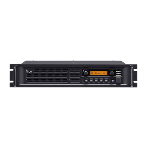
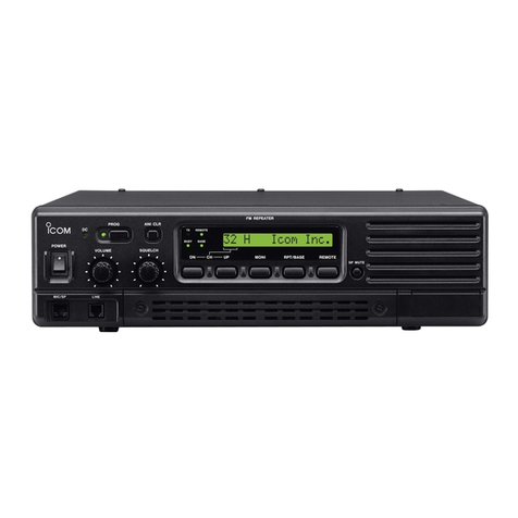
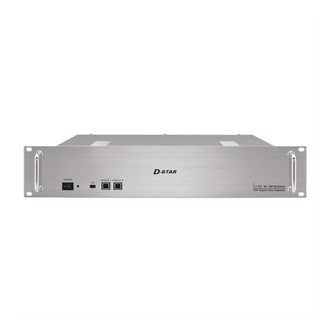
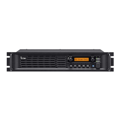
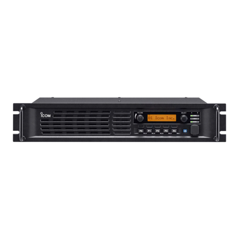
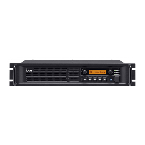
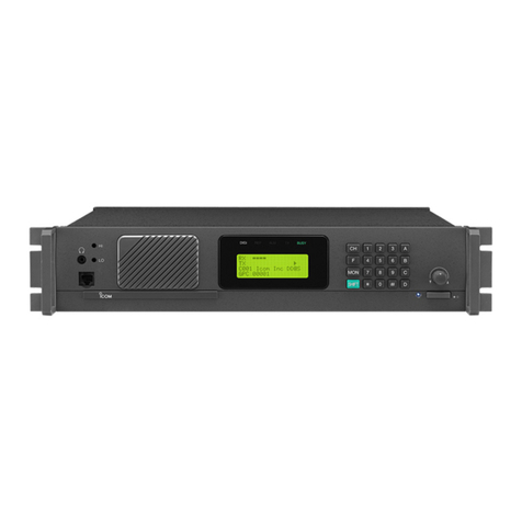
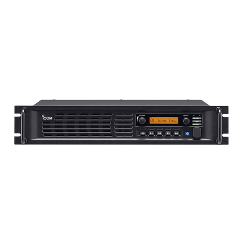
Icom ID-RP2C User manual

2001 NEW
DIGITAL REPEATER SYSTEM
id- rp2
Instruction Manual
NOTE:
This instruction manual is about the ID-RP2C with-
out the assist function. If you are using the function,
refer to the ID-RP2C instruction manual with the as-
sist function.

2001 NEW
IMPORTANT
READ THIS INSTRUCTION MANUAL
CAREFULLY before installing or operating the
repeater.
SAVE THIS INSTRUCTION MANUAL. This
manual contains important safety and operating
instructions for the ID-RP2 system.
EXPLICIT DEFINITIONS
i
WORD DEFINITION
RDANGER!
Personal death, serious injury or an ex-
plosion may occur.
RWARNING!
Personal injury, fire hazard or electric
shock may occur.
CAUTION Equipment damage may occur.
NOTE
If disregarded, inconvenience only. No risk
or personal injury, fire or electric shock.
PRECAUTIONS
RDANGER! ID-RP2 installation, is intended for professional
installation only. We are not responsible for any building
breakage, any damage resulting from a drop of the antenna
from a high place or unstable site or resulting from any
personal injury nor any accident in any other cases. Be sure
to consult an expert engineer for installations.
RWARNING RF EXPOSURE! This device emits Radio
Frequency (RF) energy. Extreme caution should be
observed when operating this device. If you have any
questions regarding RF exposure and safety standards
please refer to the Federal Communications Commission
Office of Engineering and Technology’s report on Evaluating
Compliance with FCC Guidelines for Human Radio
Frequency Electromagnetic Fields (OET Bulletin 65).
RWARNING HIGH VOLTAGE! NEVER attach an antenna
or internal antenna connector during transmission. This may
result in an electrical shock or burn.
RWARNING HIGH VOLTAGE! NEVER install the antenna
at any location where a person could easily touch the
antenna during transmission. This may result in an electrical
shock or burn.
RWARNING! NEVER apply AC to the [DC 13.8V IN]
connector. This could cause a fire or damage the repeater.
RWARNING! NEVER apply more than 16 V DC to the
[DC 13.8V IN] connector on the repeater. This could cause
a fire or damage the repeater.
RWARNING! NEVER let metal, wire or other objects touch
any internal part or connectors on the repeater. This may
result in an electric shock or this could cause a fire or may
damage the repeater.
RWARNING! NEVER operate or touch the repeater unit,
ID-RP2C, ID-RP2D and ID-RP2V, with wet hands. This may
result in an electric shock or may damage to the repeater
unit.
RWARNING! NEVER connect the repeater to a power
source using reverse polarity. This will damage the repeater.
Make sure the repeater power is turned OFF when connect-
ing a power supply.
DO NOT use or place the repeater unit, ID-RP2C, ID-RP2D
and ID-RP2V, in areas with temperatures below –10°C
(+14°F) or above +50°C (+122°F).
DO NOT place the repeater unit, ID-RP2C, ID-RP2D and
ID-RP2V, in excessively dusty environments or in direct
sunlight.
DO NOT place the repeater unit, ID-RP2C, ID-RP2D and ID-
RP2V against walls or putting anything on top of the units.
This will obstruct heat dissipation.
DO NOT use harsh solvents such as benzine or alcohol
to clean the repeater, as they will damage the repeater’s
surfaces. If the repeater becomes dusty or dirty, wipe it clean
with a soft, dry cloth.
DO NOT modify the repeater for any reason.
Place the repeater in a secure place to avoid inadvertent use
by children.
Use the specified fuse only.
For U.S.A. only
CAUTION: Changes or modifications to this repeater, not
expressly approved by Icom Inc., could void your authority to
operate this repeater under FCC regulations.
Icom is not responsible for the destruction or damage to
the Icom product, if the malfunction is because of:
• Force majeure, including, but not limited to, fires, earth-
quakes, storms, floods, lightning, other natural disasters,
disturbances, riots, war, or radioactive contamination.
• The use of Icom products with any equipment that is not
manufactured or approved by Icom.
Icom, Icom Inc. and Icom logo are registered trademarks of Icom
Incorporated (Japan) in Japan, the United States, the United
Kingdom, Germany, France, Spain, Russia, Australia, New Zealand,
and/or other countries.
Microsoft, Windows is either registered trademarks or trademarks
of Microsoft Corporation in the United States and/or other countries.
All other products or brands are registered trademarks or trademarks
of their respective holders.
ii
TABLE OF CONTENTS
FCC INFORMATION
This equipment has been tested and found to comply
with the limits for a Class B digital device, pursuant to
part 15 of the FCC Rules. These limits are designed to
provide reasonable protection against harmful interfer-
ence in a residential installation. This equipment gen-
erates, uses and can radiate radio frequency energy
and, if not installed and used in accordance with the
instructions, may cause harmful interference to radio
communications. However, there is no guarantee that
interference will not occur in a particular installation.
If this equipment does cause harmful interference to
radio or television reception, which can be determined
by turning the equipment off and on, the user is en-
couraged to try to correct the interference by one or
more of the following measures:
• Reorient or relocate the receiving antenna.
• Increase the separation between the equipment
and receiver.
• Connect the equipment into an outlet on a circuit dif-
ferent from that to which the receiver is connected.
• Consult the dealer or an experienced radio/TV tech-
nician for help.
IMPORTANT ............................................................. i
EXPLICIT DEFINITIONS........................................... i
PRECAUTIONS......................................................... i
FCC INFORMATION.................................................ii
1 SYSTEM OUTLINE.............................................. 1
■ID-RP2C............................................................ 1
■ID-RP2D............................................................ 1
■ID-RP2V............................................................ 1
■AH-108: 1.2 GHz Collinear antenna ................. 1
2 SUPPLIED ACCESSORIES ................................ 2
■Accessories for ID-RP2C ................................. 2
■Accessories for ID-RP2D/ID-RP2V................... 2
■Accessories for AH-108 .................................... 2
3 PANEL DESCRIPTIONS ................................. 3–5
■ID-RP2C (Front panel)...................................... 3
■ID-RP2C (Rear panel)....................................... 3
■ID-RP2D (Front panel)...................................... 4
■ID-RP2D (Rear panel)....................................... 4
■ID-RP2V (Front panel) ...................................... 5
■ID-RP2V (Rear panel)....................................... 5
4 INSTALLING AND CONNECTING.................. 6–8
■Attaching an “N” connector ............................... 6
■Power supply requirements .............................. 6
■Installing in a system rack................................. 6
■Attaching the rubber feet .................................. 6
■Grounding ......................................................... 6
■System connections.......................................... 7
■Antenna assembling ......................................... 8
DAH-108 .......................................................... 8
5 DRIVER INSTALLATIONS ............................ 9–17
■Microsoft® Windows®8.1 .................................. 9
■Microsoft® Windows®7 ................................... 12
■Checking the COM port ................................. 14
DMicrosoft®Windows®8.1............................. 14
DMicrosoft®Windows®7................................ 15
■Uninstalling the USB driver............................. 16
DMicrosoft®Windows®8.1............................. 16
DMicrosoft®Windows®7................................ 17
6 INSTALLING THE UTILITY SOFTWARE.... 18–20
■Installing.......................................................... 18
■Uninstalling the Utility software....................... 20
7 REPEATER SETTINGS............................... 21–26
■ID-RP2C setting.............................................. 21
DID-RP2C utility screen................................. 22
■Frequency setting for ID-RP2D....................... 25
■Frequency setting for ID-RP2V....................... 26
8 MAINTENANCE........................................... 27–28
■Troubleshooting .............................................. 27
■Cleaning.......................................................... 28
■Replacing fuses .............................................. 28
DOPC-1309 ................................................... 28
DOPC-1380 ................................................... 28
9 SPECIFICATIONS AND OPTIONS ............. 29–30
■Specifications.................................................. 29
DID-RP2C...................................................... 29
DID-RP2D/ID-RP2V....................................... 30
■Options ........................................................... 30
10 INFORMATION................................................. 31
■About CE and DOC......................................... 31
■Disposal .......................................................... 31
■Country code list ............................................. 31

2001 NEW
1SYSTEM OUTLINE
2001 NEW
1
A Digital Smart Technologies for Amateur Radio (D-
STAR) repeater can be constructed by combining the
following equipment, depending on your site plan.
ID-RP2C: Repeater controller
ID-RP2D: 1.2 GHz data repeater
ID-RP2V: 1.2 GHz digital voice repeater
In addition, the following options may also be required
for system repeater operations.
AH-108: 1.2 GHz Collinear antenna
■ID-RP2C
➥The ID-RP2C is a repeater controller and one con-
troller must be used in each repeater site.
The controller relays digital voice or data (traffic) sig-
nals for repeater operation.
➥A total of four interface connectors for local repeater
connections are available.
Both digital voice and data repeaters can be con-
nected as desired.
• Typical configuration:
One data repeater
One digital voice repeater
Two extra for additional repeaters.
NOTE: Connecting only 1 or 2 repeaters for the
same frequency band is recommended
to avoid interference.
➥One Ethernet port (10Base-T) is available for setting
the operating frequency, repeater site call sign, IP
address and operation monitoring, using the PC
and the ID-RP2C utility software.
Or, a gateway control PC can be connected if de-
sired.
■ID-RP2D
➥The ID-RP2D is a 1.2 GHz data (128 kbps) repeater
and connects to the ID-RP2C.
*The ID-RP2D never functions as a stand-alone repeater
without the ID-RP2C, because no relay function is built-in.
➥The ID-RP2D and ID-RP2V utility software, sup-
plied with the ID-RP2C, and a PC are required for
both receive and transmit frequency settings.
➥Repeater operation is performed in simplex mode
on the same frequency for data mode. However,
different frequencies between transmit and receive
can be set in simplex mode.
■ID-RP2V
➥The ID-RP2V is a 1.2 GHz digital voice and slow-
speed data repeater (4.8 kbps) and connects to the
ID-RP2C.
*
The ID-RP2V never functions as a stand-alone repeater
without the ID-RP2C, because no relay function is built-in.
NOTE: No audio CODEC is performed in the ID-
RP2V, thus the ID-RP2V receives and
transmits 4.8 kbps serial data only.
➥Different frequencies are used for each transmis-
sion and reception in semi-duplex mode.
➥The ID-RP2D/V utility software, supplied with the
ID-RP2C, and a PC are required for both receive
and transmit frequency settings.
■AH-108: 1.2 GHz Collinear an-
tenna
➥Two collinear antennas are built-in and better isola-
tion is provided than two separated antennas.
About the ID-RP2C Utility software:
The ID-RP2C boxed with this instruction manual
requires the utility software revision 2.2 or later.
The utility software revision 2.0 or earlier is not
compatible.

2
2
SUPPLIED ACCESSORIES
2001 NEW
■Accessories for ID-RP2C
w
e
r
q
q Power cable (OPC-1380; approximately. 3 m; 10 ft) .. 1
wCD (USB driver, Utility software)........................... 1
eRubber feet ........................................................... 4
rSpare fuses (FGB01 30A) ...................................... 2
■Accessories for ID-RP2D/ID-RP2V
r
w
e
q
q Power cable (OPC-1309; approximately. 1 m; 3.3 ft)
... 1
wControl cable (OPC-1069) approximately. 3 m; 9.8 ft).. 1
eRubber feet ........................................................... 4
rSpare fuses (FGB10A) ........................................... 2
NOTE: Coaxial cables, USB and LAN cables and
other hardware needed for installation, that
are not listed in this manual as supplied,
must be purchased separately.
■Accessories for AH-108
qwe
rt y
ui
q Pole clamps ......................................................... 8
wBolts (M8×160) ....................................................... 4
eFlat washers (M8) ............................................... 12
rNuts (M8) .............................................................. 8
tSpring washers (M8) ............................................. 8
yRubber vulcanizing tape (approximately. 60 cm; 2 ft) 1
uRadials ................................................................. 4
iNuts (M6) .............................................................. 4

3
3
PANEL DESCRIPTIONS
2001 NEW
■ID-RP2C (Front panel)
qPOWER SWITCH [POWER]
Push to turn ON the power.
The LED indicator located at right lights when the
power is turned ON.
w10BASE-T CONNECTOR [10BASE-T] (p. 24)
Connects a PC with LAN cable to set the details of
the repeater site, such as the call sign, IP address.
A Gateway server can also be connected to this
connector.
qw
■ID-RP2C (Rear panel)
qPOWER CONNECTORS
[LOCAL RPT— DC13.8V OUT] (p. 7)
Outputs 13.8 V DC for local repeater.
Connects the ID-RP2D/V with the supplied DC
power cable (OPC-1309; supplied with the ID-RP2D/V).
The same voltage as the supplied voltage to
[DC13.8V IN] connector is output regardless of the
[POWER] switch condition on the front panel.
w[LOCAL RPT— CONT I/O] (p. 7)
Input/output ports for local repeater to received or
transmitted serial data routing.
Connects the ID-RP2D/V with the supplied control
cable (supplied with the ID-RP2D/V).
ePOWER CONNECTOR [DC 13.8V IN] (p. 7)
DC power input connector for the ID-RP2 system.
Connects a 13.8 V DC power supply unit with the
DC power cable (OPC-1380; supplied with the ID-
RP2C).
rGROUND TERMINAL [GND] (p. 10)
Connects to a ground to prevent electrical shocks,
TVI, BCI and other problems.
qw e r

4
3
PANEL DESCRIPTIONS
■ID-RP2D (Front panel)
qPOWER SWITCH [POWER]
Push to turn ON the power.
The LED indicator located at right lights when the
power is turned ON.
wHIGH/LOW POWER SELECT SWITCH [H/L]
Select either High (approximately 10 W) or Low
(approximately 1 W) output power.
eSERVICE CONNECTOR [SERVICE] (p. 25)
Connects a PC with an A-B type USB cable to set
the both transmit and receive frequencies.
(User supplied cable)
qwe
■ID-RP2D (Rear panel)
qANTENNA CONNECTOR [ANT] (p. 7)
Connect the optional AH-108 1.2 GHz Collinear
antenna.
When both the ID-RP2D and ID-RP2V is com-
posed in a site, an antenna filter, such as band-
pass filter, resonator, or so, should be installed be-
tween the ID-RP2D and antenna to protect the ID-
RP2D reception from interference of the ID-RP2V
downlink signal.
wCOOLING FAN
ePOWER CONNECTOR [DC13.8V] (p. 7)
Connects to the ID-RP2C with the supplied DC
power cable (OPC-1309) to be supplied the DC
power.
r[CONT I/O] (p. 7)
Connects to ID-RP2C with the supplied control
cable for received or transmitted serial data com-
munication.
tGROUND TERMINAL [GND] (p. 6)
Connects to a ground to prevent electrical shocks,
TVI, BCI and other problems.
qwe r t

5
3PANEL DESCRIPTIONS
2001 NEW
■ID-RP2V (Front panel)
qPOWER SWITCH [POWER]
Push to turn ON the power.
The LED indicator located at right lights when the
power is turned ON.
wHIGH/LOW POWER SELECT SWITCH [H/L]
Select either High (approximately 10 W) or Low
(approximately 1 W) output power.
eSERVICE CONNECTOR T [SERVICE T] (p. 26)
Connects a PC with an A-B type USB cable to set
the transmit frequency. (User supplied cable)
rSERVICE CONNECTOR R [SERVICE R] (p. 26)
Connects a PC with an A-B type USB cable to set
the receive frequency. (User supplied cable)
qwe r
■ID-RP2V (Rear panel)
qRECEIVE ANTENNA CONNECTOR [ANT] (p. 7)
Connect the optional AH-108 1.2 GHz Collinear
antenna separately, or through a duplexer.
w
TRANSMIT ANTENNA CONNECTOR [ANT] (p. 7)
Connect the optional AH-108 1.2 GHz Collinear
antenna through a duplexer.
eCOOLING FAN
NOTE: Keep the area around the fan free from
obstacles.
rPOWER CONNECTOR [DC13.8V] (p. 7)
Connects to the ID-RP2C with the supplied DC
power cable (OPC-1309) to supply the DC power.
t[CONT I/O] (p. 7)
Connects to the ID-RP2C with the supplied control
cable for serial data communications.
yGROUND TERMINAL [GND] (p. 6)
Connects to a ground to prevent electrical shocks,
TVI, BCI and other problems.
qerw t y

2001 NEW
4
6
INSTALLING AND CONNECTING
■Attaching an “N” connector
Use 50 Ωconnectors and coaxial cable.
Use “N” type connectors between the repeater and the
antennas.
Slide the nut, washer
,
rubber gasket and clamp
over the coaxial cable,
then
cut the end of the cable
evenly.
Strip the cable and fold
the
braid back over the clamp.
Tin the center conductor
.
Install the center
conductor
pin and solder it.
Carefully slide the plug
body into place aligning the
center conductor pin on the
cable. Tighten the nut
onto
the plug body.
q
w
e
r
15 mm (0.59 in) 6 mm (0.24 in) 3 mm (0.12 in)
15 mm
3 mm 6 mm
No space
Solder hole
Be sure the center conductor is
the same height as the plug body.
Clamp Center
conductor
Washer
Nut Rubber gasket
■Power supply requirements
Make sure that the DC power supply that is used
with the ID-RP2 system is meet the following
requirements:
Output voltage: 13.8 V DC ±15%
Currentcapacity: At least the total current
consumption of the connected
equipment, with consideration for
current fluctuations.
■Installing in a system rack
The ID-RP2C/D/V are designed to be installed in a
standard EIA 19-inch rack.
Use the supplied bolts with the rack when fixing the
ID-RP2C/D/V.
We recommend using a rack that has rails because the
weigh of the ID-RP2D and ID-RP2V is approximately
6.2 kg (13.7 lbs) and approximately 7.5 kg (16.5
lbs), respectively.
■Attaching the rubber feet
For desktop installations, attach the supplied rubber
feet onto the bottom of the ID-RP2C/D/V as shown
below.
■Grounding
To prevent electrical shock, television interference
(TVI), broadcast interference (BCI) and other problems,
ground the transceiver through the GROUND terminal
on the rear panel.
For best results, connect a heavy gauge wire or strap
to a long earth-sunk copper rod.
Make the distance between the [GND] terminal and
ground as short as possible.
RWARNING: NEVER connect the [GND] a gas
or electric pipe, since the connection could cause
an explosion or electric shock.
q• Cross section
w

7
4INSTALLING AND CONNECTING
2001 NEW 2001 NEW
Antenna
filter
Duplexer
ID-RP2V
Coaxial cables
(purchase separately)
ID-RP2D
ID-RP2C
OPC-1380
(supplied w/ID-RP2C)
OPC-1309
(supplied w/ID-RP2D/V)
OPC-1309
(supplied w/ID-RP2D/V)
Control cable
(supplied w/ID-RP2D/V)
Control cable
(supplied w/ID-RP2D/V)
AH-108*
AC outlet
AC power cable
External DC power
supply 13.8 V
Black
_
Red
+
*Not available in European countries
as of November 2017.
■System connections

8
4
INSTALLING AND CONNECTING
2001 NEW
■Antenna assembling
DAH-108
Pole
(30–60 mm)
Spring washer
Flat washer
Nut
Plating area
Nut Radial
AH-108
Pole clamps
Pole clamps
AH-108
qAttach the nut (M6) to the radial, then attach the ra-
dial to the AH-108.
wAttach the supplied bolts, pole clamps, spring wash-
ers, flat washers and nuts to the AH-108 as illus-
trated at left.
CAUTION!: The pole clamps must be attached
to the plating area only. Attachment to other part
may cause damage of the AH-108 due to
strength shortage.
eFix the AH-108 to the pole using with the supplied
pole clamps, spring washers, flat washers and
nuts.
(Not available in European countries)

5
9
DRIVER INSTALLATIONS
2001 NEW 2001 NEW2001 NEW
Use an A-B type USB (Universal Serial Bus) cable be-
tween the ID-RP2 and your PC. So, the USB driver
installation is required for the PC.
In addition, individual USB driver installations are re-
quired for each connector, because the communica-
tion port numbers are different.
The instruction that follow describe the installation of
the ID-RP2D [SERVICE] connector as an example. NOTE:
The repeater unit connection may not be recognized
by the PC if the USB cable is too long. Use as short
a USB cable as possible.
qStart Windows.
• Quit all other applications if any are running.
• When installing the driver, log in as the administrator.
wInsert the CD that is supplied with the ID-RP2C (Ap-
plication CD) into the CD drive.
• If you downloaded the USB driver, skip this step and go
to the next step.
e
Connect the PC and the ID-RP2D [SERVICE] connec-
tor with an A-B type USB cable (User supplied).
rMove the mouse pointer to the bottom left corner of
the desktop.
Move the mouse pointer
around here.
tRight-click the Microsoft icon, and then click “Device
Manager.”
Click
Right-click
yThe “Device Manager” window appears, then make
sure a warning symbol “ ” is displayed, as shown
below.
NOTE: Although the warning symbol “ ” indicates that
the driver installation has failed, continue the proce-
dure.
■Microsoft® Windows®8.1
IMPORTANT!
A different USB driver from the ID-1 is used for the
ID-RP2 system.
Uninstall the USB driver for ID-1 first, then install
the USB driver for the ID-RP2 system, if the USB
driver for the ID-1 is installed in the PC.

10
2001 NEW2001 NEW
10
5
DRIVER INSTALLATIONS
uRight-click on the device icon with the warning sym-
bol “ ,” and then click “Update Driver Software...” on
the menu.
wClick
qRight-click
iThe window shown below will appear.
Click “Browse my computer for driver software.”
Click
oThe “Browse for driver software on your computer”
will appear.
Click [Browse...].
Click
!0 Select the “DRIVER” folder in the application CD,
or the unzip driver file (downloaded driver file), and
then click [OK].
Click
Select
!1 Click [Next] to start the installation of “ID-RP2D
SERVICE” driver software.
Click
!2 When the Windows Security screen appears, click
[Install] to continue.
Click

11
5DRIVER INSTALLATIONS
2001 NEW 2001 NEW
!3 After the installation is completed, the “Windows
has successfully updated your driver software” will
appear.
Click [Close].
Click
!4 Again, right-click on the device icon with the warn-
ing symbol “ ” in the “Device manager,” and then
click “Update Driver Software...” on the menu.
!5 Repeat uto !3, to install the “ID-RP2D SERVICE”
driver software.
!6 Eject the CD from the CD drive, and then restart the
PC.
■Microsoft®Windows®8.1— Continued

12
2001 NEW
5
DRIVER INSTALLATIONS
■Microsoft® Windows®7
qStart Windows.
• Quit all other applications if any are running.
• When installing the driver, log in as the administrator.
wInsert the CD that is supplied with the ID-RP2C (Ap-
plication CD) into the CD drive.
• If you download the USB driver, skip this step and go to
the next step.
eConnect the PC and the ID-RP2D [SERVICE] con-
nector with an A-B type USB cable (User supplied).
Then the dialog shown below will appear.
rThe “Device driver software was not successfully in-
stalled” will appear soon.
tMove the mouse pointer to the bottom left corner of
the desktop.
Click the Windows “START” icon, right-click “Com-
puter” in the <Start> menu, and then click “Proper-
ties.”
qClick
wRight-click
eClick
yThe “Control Panel Home” window will appear.
Click “Device Manager.”
Click
uThe “Device Manager” window appears, then make
sure a warning symbol “ ” is displayed, as shown
below.
NOTE: Although the warning symbol “ ” indicates that
the driver installation has failed, continue the proce-
dure.
iRight-click on the device icon with the warning sym-
bol “ ,” and then click “Update Driver Software...” on
the menu.
Right-click
Click
oThe window shown below will appear.
Click “Browse my computer for driver software.”
Click

13
5DRIVER INSTALLATIONS
2001 NEW 2001 NEW
!0 The “Browse for driver software on your computer”
will appear. Click [Browse...].
Click
!1 Select the “DRIVER” folder in the application CD,
or the unzip driver file (downloaded driver file), and
then click [OK].
Click
Select
!2 The “Browse for driver software on your computer”
will appear again.
Click [Next] to start the installation of “ID-RP2D
SERVICE.”
Click
!3 When the Windows Security screen appears, click
[Install] to continue.
Click
!4 After the installation is completed, “Windows has
successfully updated your driver software” will ap-
pear as shown below. Click [Close].
Click
!5 The dialog “Device driver software was not success-
fully installed” will appear again.
!6 Repeat ito !4, to install the “ID-RP2D SERVICE”
driver software.
!7 Eject the CD from the CD drive, and then restart the
PC.
■Microsoft®Windows®7— Continued

14
2001 NEW
5
DRIVER INSTALLATIONS
■Checking the COM port
DMicrosoft®Windows®8.1
qStart Windows.
• When opening the Device Manager, log in as the admin-
istrator.
wConnect the PC and the ID-RP2D [SERVICE] con-
nector with the USB cable.
eMove the mouse pointer to the bottom left corner of
the desktop.
Move the mouse pointer
around here.
rRight-click the Microsoft icon, and then click “Device
Manager.”
• The “Device Manager” window appears.
wClick
qRight-click
tDouble-click “Ports (COM&LPT)” on the “Device
Manager” screen to check the COM port number.
• When the driver is completely installed, “ICOM ID-RP2D
SERVICE (COMM)” is displayed. The screen shows the
USB serial COM port number “4.”
Double-click
• The COM port number is displayed instead of “M.”
If the repeater has two COM ports, two COM port
numbers are displayed.
• Depending on the PC environment, the COM port
number may differ.
• If “!” or “×” is displayed on the “Device Manager”
screen, the driver may not be properly installed. In
this case, first uninstall the USB driver, then rein-
stall it.
After the driver installation, check the driver availability
and the COM port number.
In this section, checking the COM port number of the
ID-RP2D [SERVICE] connector is used for instruction
example.

15
5DRIVER INSTALLATIONS
2001 NEW 2001 NEW
■Checking the COM port— continued
DMicrosoft®Windows®7
qStart Windows.
• When opening the Device Manager, log in as the admin-
istrator.
wConnect the PC and the ID-RP2D [SERVICE] con-
nector with the USB cable.
eMove the mouse pointer at the left-bottom corner of
the desktop.
Click the Windows “START” icon, right-click “Com-
puter” in the <Start> menu, and then click “Proper-
ties.”
qClick
wRight-click
eClick
rThe “Control Panel Home” window will appear.
Click “Device Manager.”
• The “Device Manager” window appears.
Click
tDouble-click “Ports (COM&LPT)” on the “Device
Manager” screent o check the COM port number.
• When the driver is completely installed, “ICOM ID-RP2D
SERVICE (COMM)” is displayed. The screen shows the
USB serial COM port number “4.”
Double-click
• The COM port number is displayed instead of “M.”
If the repeater has two COM ports, two COM port
numbers are displayed.
• Depending on the PC environment, the COM port
number may differ.
• If “!” or “×” is displayed on the “Device Manager”
screen, the driver may not be properly installed. In
this case, first uninstall the USB driver, then rein-
stall it.

16
5
DRIVER INSTALLATIONS
2001 NEW
■Uninstalling the USB driver
DMicrosoft®Windows®8.1
qStart Windows.
• When uninstalling the driver, log in as the administrator.
w
Connect the PC and the ID-RP2D [SERVICE] connec-
tor with the USB cable.
eMove the mouse pointer to the bottom left corner of
the desktop.
Right-click the Microsoft icon, and then click “Device
Manager.”
• The “Device Manager” window appears.
rDouble-click “Ports (COM&LPT)” on the “Device
Manager” screen.
• “ICOM ID-RP2D SERVICE (COMM)” appears.
tRight-click “ICOM ID-RP2D SERVICE (COMM)” and
then click “Uninstall.”
qRight-click
wClick
yThe “Confirm Device Uninstall” window will appear.
Check “Delete the driver software for this device.”
and then click [OK].
Click
uDouble-click “Universal Serial Bus controllers” on
the “Device Manager” screen.
• “ICOM ID-RP2D SERVICE” appears.
Double-click
iRight-click “ICOM ID-RP2D SERVICE” and then
click “Uninstall.”
qRight-click
wClick
oThe “Confirm Device Uninstall” window will appear.
Check “Delete the driver software for this device.”
and then click [OK].
Click
!0 Restart the PC.

17
5DRIVER INSTALLATIONS
2001 NEW
DMicrosoft®Windows®7
qStart Windows.
• When uninstalling the driver, log in as the administrator.
w
Connect the PC and the ID-RP2D [SERVICE] connec-
tor with a USB cable (A-B type: purchase separately).
eMove the mouse pointer at the left-bottom corner of
the desktop.
Click the Windows “START” icon, right-click “Com-
puter” in the <Start> menu, and then click “Proper-
ties.”
rThe “Control Panel Home” window will appear.
Click “Device Manager.”
• The “Device Manager” window appears.
tDouble-click “Ports (COM&LPT)” on the “Device
Manager” screen.
• “ICOM ID-RP2D SERVICE (COMM)” appears.
yRight-click “ICOM ID-RP2D SERVICE (COMM)” and
then click “Uninstall.”
qRight-click
wClick
uThe “Confirm Device Uninstall” window will appear.
Check “Delete the driver software for this device.”
and then click [OK].
Click
iDouble-click “Universal Serial Bus controllers” on
the “Device Manager” screen.
• “ICOM ID-RP2D SERVICE” appears.
Double-click
oRight-click “ICOM ID-RP2D SERVICE” and then
click “Uninstall.”
qRight-click
wClick
!0 The “Confirm Device Uninstall” window will appear.
Check “Delete the driver software for this device.”
and then click [OK].
Click
!1 Restart the PC.
■Uninstalling the USB driver— continued
This manual suits for next models
3
Table of contents
Other Icom Repeater manuals

Icom
Icom iFR5200H User manual

Icom
Icom FR5000 Operating instructions

Icom
Icom X BAND 50 User manual

Icom
Icom IC-FR5000 Series User manual

Icom
Icom id- rp2 User manual

Icom
Icom FR3000 User manual

Icom
Icom IC-FR3000 Series User manual

Icom
Icom iC-FR5000 User manual

Icom
Icom IC-FR4000 Series User manual

Icom
Icom IC-RP4520 User manual