FiberHome AN5506-04-FA User manual

FiberHome AN5506-04-FA
Instruction
Version FiberHome AN5506-04-FA
1. AN5506-04-FA Router power status
2. Internet connection Settings
3. WAN, Wireless Settings
4. DHCP Settings
5. Bridge Mode Settings
6. Forward Port Settings
7. Dynamic DNS Settings
8. Power Checking
9. Product version, Hardware and software Checking
10. Firmware Upgrading
11. Restoring to Default
12. Ping and Traceroute
13. Hardware Installation
14. Technical Specification
15. Product Overview
16. Packing List

1. AN5506-04-FA Router power status
หมายเลข
ชื่อสัญลักษณ์
สถานะไฟ
รายละเอียด
1
POWER
Steady
green
The terminal is powered on.
Steady
orange
The device is powered by a backup battery.
Off
The power supply is cut off.
2-3
Off
Off
The GPON terminal is prohibited by the upper-layer device, contact the
service provider for help.
Blinks twice a
second
Off
The GPON terminal attempts to set up a connection with its upper-layer
device.
Steady on
Off
A connection is set up between the GPON terminal and its upper-layer
device.
Off
Blinks
once two
seconds
The GPON terminal is not connected to optical fibers or does not receive
optical signals.
Blinks twice a
second
Blinks
twice a
second
The GPON terminal is a rogue terminal, contact the service provider for
help.
Blinks once
two seconds
Blinks
once two
seconds
The hardware is faulty.
Off
Off
The GPON terminal is prohibited by the upper-layer device, contact the
service provider for help.
4
Internet
Steady on
Able to connect to the Internet
Off
Unable to connect to the Internet
Blinking
The device is in the process of receiving / sending Internet data.
5
USB
USB connection status indicator
6
LAN1 - LAN4
Steady on
The Ethernet connection is in the normal state.
Blinking
Data is being transmitted on the Ethernet port.
Off
The Ethernet connection is not set up.
7
VOIP
VoIP connection indicator
8
Phone1-
Phone2
Indicator light connecting to VoIP
9,11
WIFI1,WIFI2
Wireless connection Indicator light If it is in use, sending/receiving data, the light will be flashing
green.
10,12
WPS1,WPS2
Steady on
The device has an unencrypted wireless connection, it is ready to use
Blinking
The device has an unencrypted wireless connection, it's ready to use and Currently
connected
Off
The device is not connected to WPS.

2. Internet connection Settings
There are 2 type to set the Internet connection
Type 1. Shortcut
- Open the browser and enter 192.168.1.1/3bb
- In the Quick Configuration page that is displayed, enter Username/Password that you can check from
installation report
- Enter validate code as shown.
- Click Apply
- After finished, enter URL Website to access Internet
Type 2. General
- Open the browser and enter 192.168.1.1
- In the login window, enter the username, password (They are located on the sticker attached to the bottom of the
router)
- Enter the Validate Code as shown.
- Click Login to enter the WAN, Wireless settings
Sample picture: The username and password are located on the sticker attached to the bottom of the router.

3. WAN, Wireless Settings
3.1 WAN settings
When you login to the system, you will see various menu.
Follow these steps:
- Click Network(1) Click BroadBand Settings(2) Screen showing Internet Settings
Follow these settings(3)
- Service Type ;Choose INTERNET
- Connection Type ;Route
- VLAN ID ;33
- Priority ;0
- MTU ;1492(set between 1280-1492)
- IP Mode(4); IPv4 (Choose by device’s capacity that customer use for example IPv4,IPV6 or
IPV4&IPV6 )
- WAN IP Mode(5); Choose PPPoE
- Enter Username/Password(6)You can check from installation report
- Click Apply(7)
- After finished, enter URL Website to access Internet
3.2 Wireless Settings
There are 2 step to set wireless connection
Step 1: Set all for Wireless 2.4G or Wireless 5G
- Click Network(1) Click Wlan Settings(2)
- Click Basic(3) for Wireless 2.4G or 5G Basic(4) for Wireless 5G (You can choose to set both or just one
signal)
Follow these settings(5)

- Radio ON/Off ; Choose RADIO ON to open WiFi signal
- Network Mode ; 802.11 b/g/n (Choose the signal channel that you want)
- Frequency Bandwidth ; 40 MHz (Choose the signal’s broadness that you want )
- Frequency (Channel) ; AutoSelect (Choose the signal that you want)
- Guard interval ; Set usage time and signal quality that you want
(Short ; to use near device / Long ; to use far from device)
- Click Apply(6) after that go to step 2 to set password
Step 2 : SSID Settings for Wireless 2.4G or Wireless 5G
- Click Advanced(7)for Wireless 2.4G or 5G Advanced(8) for Wireless 5G (You can choose to set both
or just one signal)
- SSID Choice(9) ;1 (Choose the required number of signals)
; Choose Enable to open the signal
- SSID Name(10) ; Named that you want (not more than 32 characters)
- Passphrase(11) ;Enter the required password (8-63 characters can enter both letters and numbers
depend on Security Mode)
- Click Apply(12) to record Wireless settings
- After finished, enter URL Website to access the internet
4. DHCP Settings
DHCP Settings and IP Address management is IP management and distribution that do not give duplicate IP
to protect the problem when you using
- Click Network(1) --> Click DHCP Server(2) --> screen showing DHCP Service
Follow these settings(3)
- Type ; Choose Server

- DHCP Start IP ; Set the begin IP Address that you want to use
- DHCP End IP ; Set the end IP Address that you want to use
- DHCP Subnet Mask ; 255.255.255.0 You can change or use as Default
- Click Apply(4)
- DHCP Settings finished
5. Bridge Mode Settings
Click Network(1) --> Click BroadBand Settings(2) Screen showing Internet Settings
Follow these settings(3)
- Service Type ; Choose INTERNET
- Connection Type ; Choose Bridge
- VLAN ID ; VLAN ID NODE
- Priority ;0
- Click Apply(4)
- Set up the router that you want to connect to Internet, then connect both device by connecting Lan cable
to the Prepared WAN
- Bridge Mode Settings finished, you can access the internet

6. Forward Port Settings
Forward Port Settings is Port setting for IP Address to use with other device required internal LAN to connect from
external LAN such as Mobile phone, Notebook or Computer etc
- Click Application(1) --> Click Port Forwarding(2) --> Screen showing Port Forwarding
- Click Add(3) to set other settings to Forward Port
The system will show screen to set other settings as follows(4)
- WAN ; Choose INTERNET_R_VID_33
- Description ; 3BBTEST (Named that you want)
- Public Port ; 8080 (It is the inside Port number that use to view camera)
- IP ; 192.168.1.1 (It is the inside IP number that use to view camera )
- Private Port ; 8080 (It is the outside Port number that use to view camera )
- Protocol ; Choose TCP (Named that you want)
- Enable ; Set to be Enable
- Click Apply(5)
- When done, the setting’s information will show above(6)
- You can use CCTV after Forward Port settings finished
- In case if you want to set more Port numbers click Add(7) To add additional port numbers and the
information provided will show more results
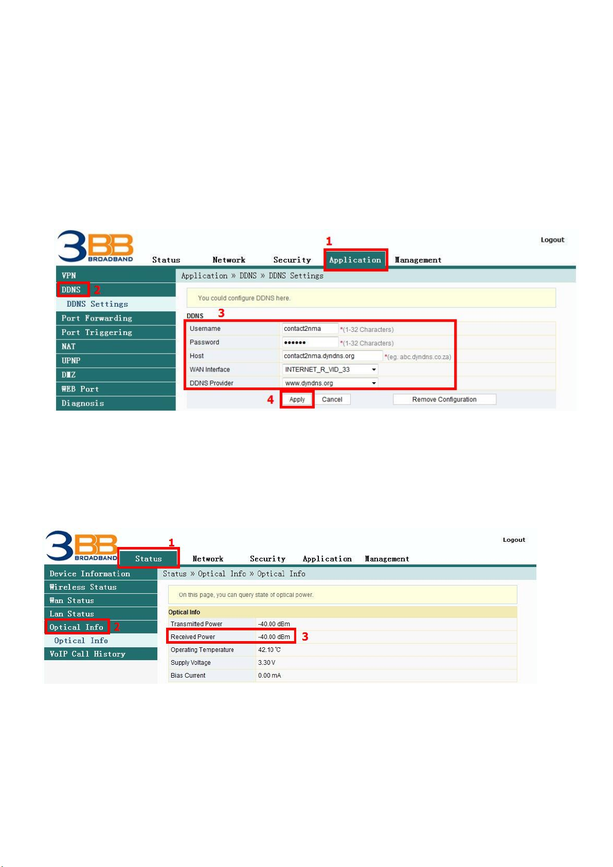
7. Dynamic DNS
Example: You apply Dyndns’s Host by use “contact2nma.dyndns.org” name, that is a domain that you can
use to view the camera from any point that no need to remember IP’s received from service providers.
- Click Application(1) --> Click DDNS(2) --> Screen showing DDNS Settings
The system will show the screen to fill in as follows(3)
- Username/Password ; As customer defined on the web of DDNS service provider (not more than 32
characters)
- Host ; contact2nma.dyndns.org (The name given on the web of DDNS service
provider.)
- WAN Interface ; INTERNET_R_VID_33 (Choose the required WAN Name)
- DDNS Provider ; www.dyndns.org (Choose a registered DDNS provider)
- Click Apply(4)
- DDNS settings finished
8. Power Checking
To check Optical Power when you have internet problem such as low speed or unstable that Optical Power
not more than -28
-Click Status(1) -->Click Optical Info(2) --> Screen showing Optical Power
- Received Power(3) ; Check Received Power not more than -28
- Power checking finished

9. Product version, Hardware and software Checking
- Click Status tab(1) Device Information(2) Product version, Hardware and software Checking(3)
10. Firmware Upgrading
It is Upgrading Firmware of device to be a new version to fix a problem of using such as internet unstable
or not compatible with other devices
- Click Management tab(1) Click Device Management(2) Click Local Upgrade(3)
- Click Browse…(4) Choose the required file after that the system will upgrade automatically
- After upgrade finish, you can Login to other settings
11. Restore to Default
There are two steps can restore to Default
Step 1 Hardware (Device reset)
- Press the Router Hardware(Reset) button and hold for 10 seconds, after that the router will restart
to be default
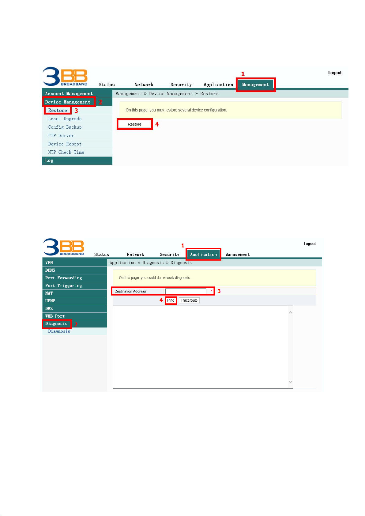
Step 2 Software(System Reset)
- Click Management(1) --> Device Management(2) --> Click Restore(3)
- Click Restore(4) Restore factory defaults
- Restore Default finished
12. Ping and Traceroute
12.1 How to Ping Test
Ping Test is using in case of connection test between ONT and destination website to check that
website, if it can use normally
- Click Application(1) -->Click Diagnosis(2) --> Screen showing Diagnosis
- Destination Address(3) ; fill in IP, Host Name or Website
- Click Ping(4) to start connection test
12.2 Traceroute Test
You can use Traceroute to check Server route connection use in case of cannot ping (the destination
website cannot be connected)
- Click Application(1) -->Click Diagnosis(2) --> Screen Showing Diagnosis
- Destination Address(3) ; fill in IP, Host Name or Website
- Click Traceroute(4)

Note :
- If ONT and the destination website can be connected will show connection such as Reply from and usage times.
- If ONT and the destination website cannot be connected will show “Ping request could not find host Please check
the name and try again”
13. Hardware Installation
Step 1 : Connect the optical fiber cable to the PON port of the GPON Terminal. (11)
Step 2 : Connect LAN cable from Port Lan of GPON Terminal to LAN Port of Computer. (6)
Step 3 : Connect the AC Adapter to the Power Port. (DC-IN)(9)
Step 4 : Press the ON/OFF button to turn on the device (8)
The following table describes the interface of the device:
No.
Port/Button
Description
1
Button
5G WPS
WPS2
The Wps1 buttom to enable or disable
the 5 Wi-Fi Protected Setup function
2
Button
5G
wireless
WLAN2
The WLAN1 button to enable or
disable the 5 WLAN function.
3
Button
2G WPS
WPS1
The Wps1 buttom to enable or disable
the 2.4 Wi-Fi Protected Setup funtion
4
Button
2G
wireless
WLAN1
The WLAN1 button to enable or
disable the 2.4 WLAN function.

5
Port Tel
Phone1,Phone2
Indicates VoIP telephone ports (RJ-
11), used to connecting to the ports
on telephone sets
6
Port
Network
LAN1 - LAN4
The USB interface connecting to the
USB storage device
7
Port
USB
USB1 , USB2
Interface connecting to the power
adapter.
8
Button
Power
ON/OFF
The Power interface connecting to the
DC Power adapter or the storage
battery.
9
Port
Power
Power
Press the button for a short time to
reset the device; press the button for
a long time (longer than 10s) to
restore the device to the default
settings and reset the device.
10
Button
Reset
Reset
The fiber interface connecting to the
optical fiber.
11
Port
Optical
PON
The USB interface connecting to the
USB storage device
14. Technical Specification
Type
Item
Description
Mechanical
parameter
Dimension
37
mmx252mmx178mm(HxWxD)
Weight
570 g approximately
Power supply
parameter
DC
DC 12V/2.5A
Power consumption
parameter
Power consumption
<15W
Environmental
parameter
Operating temperature
-5°C to - 45°C
Storage temperature
-40°C to -70°C
Environmental humidity
10% to 90% , non-condensing
15. Product Overview
product
Function
AN5506-04-FA
- 4 GE Interfaces
- 2 Phone Interfaces
- Wi-Fi Interfaces (2.4GHz, 5GHz )
- USB Interfaces
16. Packing List
Item
Quantity
GPON Terminal
1
Power Adapter
1
Ethernet Cable
1
Phone Cable
1
Quick Start
1
Other manuals for AN5506-04-FA
1
Table of contents
Other FiberHome Wireless Router manuals


