Fiberplex FAK-2981 User manual

USERMANUAL
FireAlarmKit
FAK‐2981/FAK‐2982

WarningforYourProtection
1.Readtheseinstructions.
2.Keeptheseinstructions.
3.Heedallwarnings.
4.Followallinstructions.
5.Donotusethisapparatusnearwater.
6.Cleanonlywithadrycloth.
7.Donotblockanyoftheventilationopenings.Installinaccordancewiththemanufacturer’sinstructions.
8.Donotinstallnearanyheatsourcessuchasradiators,heatregisters,stoves,orotherapparatus(includingamplifiers)thatproduceheat.
9.Onlyuseattachments/accessoriesspecifiedbythemanufacturer.
10.Unplugthisapparatusduringlightningstormsorwhenunusedforlongperiodsoftime.
11.Referallservicingtoqualifiedservicepersonnel.Servicingisrequiredwhentheapparatushasbeendamagedinanyway,suchaspower‐supply
cordorplugisdamaged,liquidhasbeenspilledorobjectshavefallenintotheapparatus,theapparatushasbeenexposedtorainormoisture,does
notoperatenormally,orhasbeendropped.
Theapparatusshallnotbeexposedtodrippingorsplashing.Noobjectsfilledwithliquids,suchasvases,shallbeplacedontheapparatus.
“WARNING:Toreducetheriskoffireorelectricshock,donotexposethisapparatustorainormoisture.”
GeneralInstallationInstructions
Pleaseconsiderthesegeneralinstructionsinadditiontoanyproduct‐specificinstructionsinthe“Installation”chapterofthismanual.
Unpacking
Checktheequipmentforanytransportdamage.Iftheunitismechanicallydamaged,ifliquidshavebeenspilledorifobjectshavefallenintothe
unit,itmustnotbeconnectedtotheACpoweroutlet,oritmustbeimmediatelydisconnectedbyunpluggingthepowercable.Repairmustonlybe
performedbytrainedpersonnelinaccordancewiththeapplicableregulations.
InstallationSite
Installtheunitinaplacewherethefollowingconditionsaremet:
Thetemperatureandtherelativehumidityoftheoperatingenvironmentmustbewithinthespecifiedlimitsduringoperationofthe
unit.Valuesspecifiedareapplicabletotheairinletsoftheunit.
Condensationmaynotbepresentduringoperation.Iftheunitisinstalledinalocationsubjecttolargevariationsofambient
temperature(e.g.inanOB‐van),appropriateprecautionsmustbetaken.
Unobstructedairflowisessentialforproperoperation.Ventilationopeningsoftheunitareafunctionalpartofthedesignandmust
notbeobstructedinanywayduringoperation(e.g.‐byobjectsplaceduponthem,placementoftheunitonasoftsurface,or
improperinstallationoftheunitwithinarackorpieceoffurniture).
Theunitmustnotbeundulyexposedtoexternalheatsources(directsunlight,spotlights).
AmbientTemperature
UnitsandsystemsbyFiberPlexaregenerallydesignedforanambienttemperaturerange(i.e.temperatureoftheincomingair)of+5...+40°C.
Whenrackmountingtheunits,thefollowingfactsmustbeconsidered:
Thepermissibleambienttemperaturerangeforoperationofthesemiconductorcomponentsis0°Cto+70°C(commercial
temperaturerangeforoperation).
Theairflowthroughtheinstallationmustallowexhaustairtoremaincoolerthan70°Catalltimes.
Averagetemperatureincreaseofthecoolingairshallbeabout20C°,allowingforanadditionalmaximum10C°increaseatthe
hottestcomponents.
Ifthecoolingfunctionoftheinstallationmustbemonitored(e.g.forfanfailureorilluminationwithspotlamps),theexhaustairtemperaturemust
bemeasureddirectlyabovethemodulesatseveralplaceswithintheenclosure.
Warranty,ServiceandTermsandConditionsofSale
ForinformationaboutWarrantyorServiceinformation,pleaseseeourpublished‘TermsandConditionsof
Sale’.Thisdocumentisavailableonfiberplex.comorcanbeobtainedbyrequestingitfrom
[email protected]orcalling301.604.0100.

Disposal
DisposalofPackingMaterials
Thepackingmaterialshavebeenselectedwithenvironmentalanddisposalissuesinmind.Allpackingmaterial
canberecycled.Recyclingpackingsavesrawmaterialsandreducesthevolumeofwaste.Ifyouneedto
disposeofthetransportpackingmaterials,recyclingisencouraged.
DisposalofUsedEquipment
Usedequipmentcontainsvaluablerawmaterialsaswellassubstancesthatmustbedisposedof
professionally.Pleasedisposeofusedequipmentviaanauthorizedspecialistdealerorviathepublicwaste
disposalsystem,ensuringanymaterialthatcanberecycledhasbeen.Pleasetakecarethatyourused
equipmentcannotbeabused.Afterhavingdisconnectedyourusedequipmentfromthemainssupply,make
surethatthemainsconnectorandthemainscablearemadeuseless.
Disclaimer
Theinformationinthisdocumenthasbeencarefullycheckedandisbelievedtobeaccurateatthetimeof
publication.However,noliabilityisassumedbyFiberPlexforinaccuracies,errors,oromissions,norforlossor
damageresultingeitherdirectlyorindirectlyfromuseoftheinformationcontainedherein.
Introduction
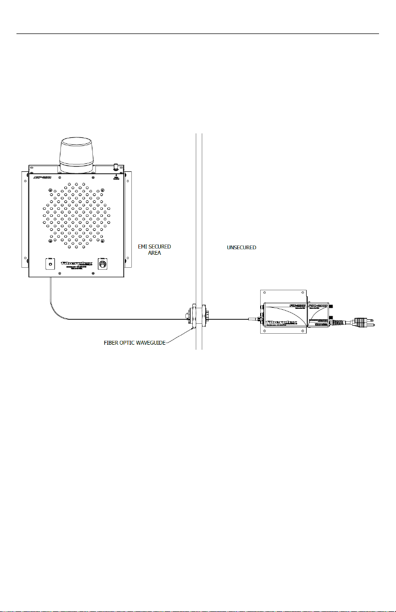
TheFAK‐2981andFAK‐2982areacompletebundledpackageforFireAlarmannunciation
applicationswith(FAK‐2981)orwithout(FAK‐2982)awarningstrobe.Thepackageincludes:
1xFOI‐2981:OpticalTransmitter
1xFOI‐4982:OpticalReceiver
1xADP‐2981ORADP‐2982:AmplifiedSpeakerwithorwithoutStrobe
1xPSQ‐2909:PowersupplyforFOI‐2981
1xWMA‐3002:WallMountAdapterforFOI‐2981
1xFC‐VM2TT1‐0‐8:FiberCable,Multimode,Simplex,ST‐ST,8mlength
TheunitutilizesFiberPlexFOIseriesmodulestoextendPublicAddressandMassNotification
systemsviafiber.Externalaudiosignalssuchasvoiceannouncements,music,adoorbellbuzz,etc.
arefirstconnectedtotheFOI‐2981.ThisFOIunitthentransmitsthesignalviaafiberopticlinkto
aFOI‐4982,convenientlyhousedandpoweredbyanADPunit.FromtheretheFOI‐4982drivesup
to10ADPunitsinadaisychain.
EachADPunitisequippedwithanACline‐poweredsupplytodrivetheamplifierandsupplyDC
powertoanattachedFOImodule.
TheADP‐2981alsocontainsastrobeannunciator,usefulforareaswithhighbackgroundnoiseor
thosewithhearingdifficulties.Aknobontopoftheunitcontrolsthevolumethresholdthatthe
audiomustexceedforthestrobetoflash.
KeyFeatures
CompletebundledpackageforFireAlarmannunciationapplications.
ADPunitsmaybelinkedonacopperaudiodaisy‐chainscheme,upto10unitslong,withnounit
configurationrequired.
UsingtheFOI‐7280,ADPunitscanbefiberdaisy‐chained
ThefiberopticisolatorisaccessibleandremovablethroughthefrontoftheADPenclosure.
Standardregionally‐appropriatepowercordsareincludedwitheachunit.
TheACmainsfuseisofacommontypeandreadilychangedwithoutdisassemblyoftheunit.
TheADPunitcanbemountedatadownwardangletofacilitatebettersoundprojectionwhen
mountedneartheceiling.
TheADPenclosureisdurable,corrosionresistantaluminumalloywithananodizedfinish.
GettingStarted
InitialInspection
Immediatelyuponreceipt,inspecttheshippingcontainerfordamage.Thecontainershouldbe
retaineduntiltheshipmenthasbeencheckedforcompletenessandtheequipmenthasbeen
checkedmechanicallyandelectrically.Iftheshipmentisincomplete,ifthereismechanical
damage,oriftheunitfailstooperatenotifyFiberPlexandmaketheshippingmaterialsavailable
forthecarrier'sinspection.
TypicalApplication
Figure1TheFAK‐2981asitistypicallyused,shownwithaFiberPlexWaveguide(notincluded)
MountingtheADPUnit
MounttheemptyADPunitusingfastenersappropriatetoyourwallorshelfconstruction
standard.Allfour(4)mountingpointsMUSTbeutilized.Ensurethatthereexistsadequate
clearanceforthepowercableandopticalfiberrun.Theunitshouldbelocatedinanenvironment
whereanambienttemperaturebetween0°and50°Cmaybemaintained.TheADPmaybe
mountedinanyorientation,providedthespeakerachievesacceptablesoundpropagationandthe
strobeisvisible.Theslotsinthemountingbracketsmaybeutilizedtoadjustthespeakerangle
downward.Toadjusttheangle,loosenthe4screwsthatattachthebracketstotheADPunit,
positiontothedesignedangleandtightenscrews.
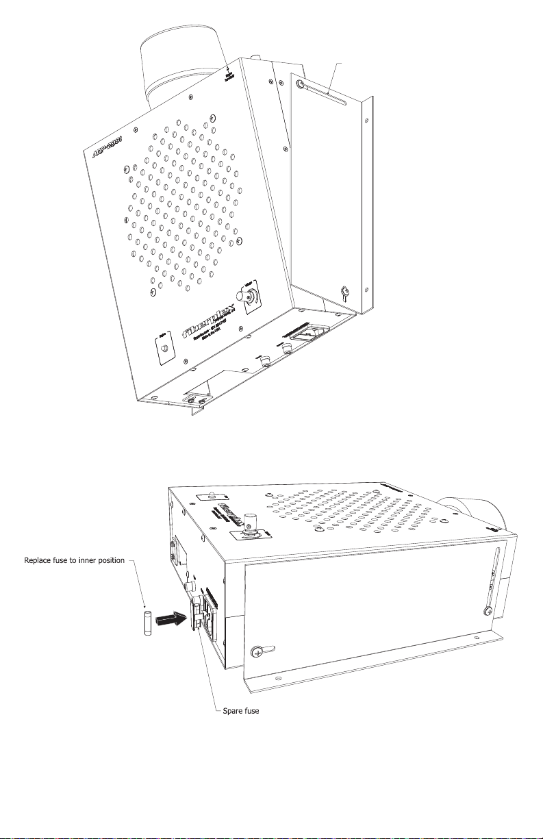
Figure2MountingtheADPUnit
Figure3FuseInstallationonanADP
SLOTS FOR ANGLED
MOUNTING

GettingStarted
PowerRequirementsandMounting
TheADPmodulewillacceptvoltagesfrom100‐240VAC,50/60Hz.Maximumpowerconsumption
is19W.TheADPmoduleconvenientlysuppliespowertoanyinstalledFOIunitviaabackplane
connector.AlthoughtheFOIcommunicationsmodulesaredesignedtobehotswappable,itis
optimalpracticetoinsertamoduleintotheADPpriortotheapplicationofACpower.
TheFOI‐2981acceptspowerfromtheincludedPSQ‐2909forfullrangeACoperation.Toassemble
thePSQ‐2909totheFOI‐2981,alongwiththeoptionalWMA‐3002mountingbracket,matethe
twomodulesasshownbelowandtightenthetwothumbscrewsonthePSQ.
Figure4FOI‐2981withWMA‐3002andPSQ‐2909
FuseReplacement
Toaccessthefuse,disconnectthepowercord,thenslideopenthecompartmentonthepower
inletandreplacethefuse.Thepowersupplyisprotectedbyasingle0.25Atime‐delayfuse
(Littlefusemodel218.250Slo‐Blo).Asparefuseisstoredontheouterpositionofthefuseholder.
Replacementfusesmusthavetherequiredcurrentratingandmustbeofthespecifiedtype.Use
ofrepairedfusesand/orbypassofthefuseholdersareprohibitedandwillvoidthewarranty.

InstallingFOIModules
ThecurrentgenerationofADPmoduleisdesignedtoacceptsize4FOImodulessuchasthe
FiberPlexFOI‐4982,butitisbackwardscompatiblewiththeolderFOI‐2982.Touseoneofthese
oldermodules,contactFiberPlexandrequestacompatibilityspacer.Thisspacerisafoampad
withanadhesivebackingthatcanbeaffixedtoeithertheinsideoftheADP,ordirectlytotheFOI
moduleitself.ThiswillensurethattheFOI‐2982slideseasilyintoplaceandfitsproperly.Please
notethatoldergenerationofADPmodulesareNOTcompatiblewiththenewerFOI‐4982.
Figure5InsertionofstandardSize4FOIModule
Figure6InsertionoflegacySize2FOIModule
Banana Plug Installed to FOI
FOI-2982 Compatibility Spacer
Features
ADP‐2981/2982Indicators/Connections
Figure7ADP‐2981bottomface(left)andtopface(right)
ModuleRetentionPlate–AfterFOImoduleisinstalled,slideplateoverandtightenscrewstosecurethe
FOIModuleinplace.
FOIModuleSlot–SlideFOIModuleintothisslotandpressfirmlyuntilpowerconnectorfullyengages.
ThefaceofthemoduleshouldbeflushwiththebottomplateoftheADP.
RCAInputJack–LinelevelaudioinputjackwhichreceivessignalfrominstalledFOIModuleoranother
ADPmoduleinadaisychain.
RCAOutputJack–LinelevelaudiooutputjackwhichpassesaudiosignaltothenextADPinadaisy
chain.
3‐pinIECACPowerInlet–AcceptsACmainspowertotheunit
StrobeSensitivityAdjustmentKnob(ADP‐2981only)–Adjuststhevolumethresholdoftheinputsignal
atwhichthestrobeannunciatoractivatestopreventbackgroundnoiseorinterferencefromactivating
thestrobelight.
StrobeLight(ADP‐2981only)–Flasheswheninputaudioexceedsthesetthreshold.
1
10
2
345
67
2
1
3
4
5
7
6
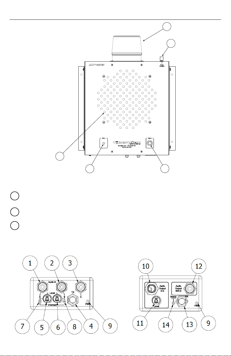
Figure8ADP‐2981frontface
8‐inchLoudspeaker–Producessounduptoa109dBmaximumsoundpressurelevel.
StatusIndicatorLED–IlluminateswhentheunitispoweredonandanFOImoduleisinserted.
VolumeAdjustmentKnob–Controlstheoutputoftheloudspeaker.
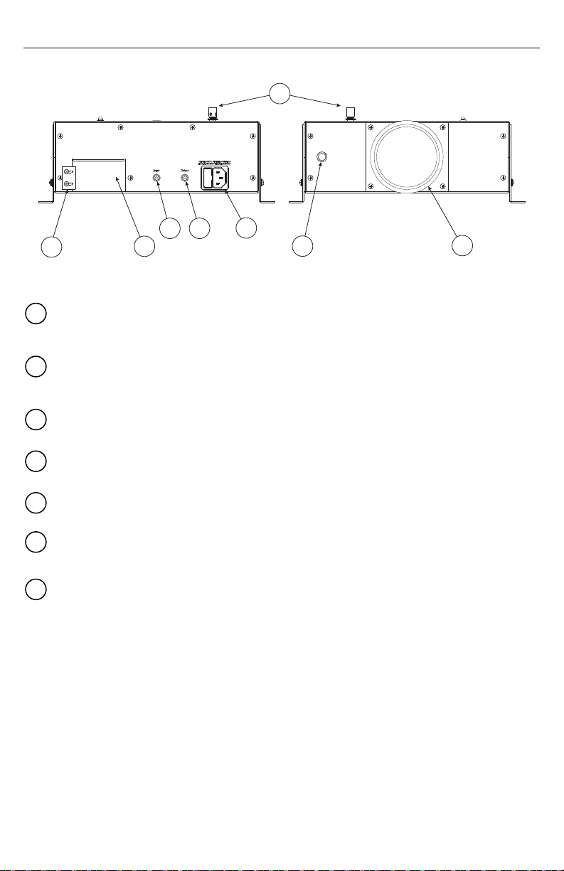
FOI‐2981andFOI‐4982Indicators/Connections
Figure9FOI‐2981(left)andFOI‐4982(right)FrontFace
8
910
6
7
8
10
9

AudioInput“A”& AudioInput“B”Jacks–Theseconnectorsacceptaudioinputsignals.Whenan
audiosignalisdetectedonthe“A”input,itwillbegivenprecedenceoveranysignalonthe“B”input,which
willbeinterrupteduntilthe“A”inputsignalends.
DoorbellOperationInputJack–AdoorbellbuzzerisgeneratedwhenthisRCAjackisgrounded.
OpticalTransmitPort–ThisSTconnectorisusedtosendtheaudiosignaloveramultimodefiberoptic
cable.
LevelAdjustmentSwitch“A”& LevelAdjustmentSwitch“B”–Theserotaryswitchesadjustthe
audiosignallevelforaudio inputs“A”and“B”.
OverloadIndicatorLED“A”& OverloadIndicatorLED“B”–TheseLEDswillilluminatewhenever
theaudioinputsignallevelis toohigh.TheLevelAdjustmentSwitchesmustbeturned
counterclockwiseuntiltheseLEDsarebothoff.Otherwise,audioclippingmayoccur.
PowerIndicatorLED–LEDwhichindicatesthepresenceofDCpowerintheunit.IfthisLEDisoff,check
thatthepowersupplyisoperatingproperly.IfusingaPSQseriespowersupplyunit,separatethePSQ
fromtheFOIunitfor30seconds,thenreconnectthemtoresettheinternalfusewithintheFOIunit.
AudioOutputJack8Ω–ThisRCAjacktransmitstheaudiosignaltoanyconnected8Ωspeaker.
OutputLevelAdjustmentSwitch–Thisrotaryswitchadjuststheaudiosignallevel.
AudioOutputJack600Ω–ThisRCAjacktransmitstheaudiosignaltoaconnectedADP‐2981orADP‐
2982.
OpticalReceivePort–ThisSTconnectorreceivestheaudiosignalfromtheconnectedFOI‐2981orFOI‐
2983.
ReadyIndicatorLED–LEDwhichilluminateswhenanopticalsignalofsufficientsignalstrengthis
detected.IfthisLEDisnotilluminated,checktheopticalconnectionsandverifythattheunitattheother
endofthefibercablehaspower.
Figure10FOIRearFace
CircularDCPowerConnection–DCpowerentryforeachunit.ThisisaLEMOconnectordesignedto
interfacewitheitheraPSQpowermoduleoranRMCchassis.
1 2
3
4
5 6
7 8
9
10
11
12
13
14
15
This manual suits for next models
1
Table of contents
Popular Fire Alarm manuals by other brands

Zeta Alarm Systems
Zeta Alarm Systems INFINITY ID2 installation manual

System Sensor
System Sensor 22051TLE-RF-26 Installation and maintenance instructions

Pittway
Pittway Notifier AM2020 troubleshooting guide

Ampac
Ampac ZoneSense user manual

Kidde
Kidde VM-1 Technical reference manual

LST
LST SIM016-3 Specification sheet


