INIM Electronics Praesidia series User manual
Guide to networking
1
FIRE DETECTION AND EXTINGUISHANT SYSTEM
EN 54-2
EN 54-4
EN 54-21
EN 12094-1 0832
0832-CPR-F1342
cert. N.991K
GUIDE TO NETWORKING

2Warranty
Fire detection and extinguishant system
Warranty
INIM Electronics s.r.l. (Seller, Our, Us) warrants the original purchaser that this product shall be free from defects in
materials and workmanship under normal use for a period of 24 months. As INIM Electronics s.r.l. does not install this
product directly, and due to the possibility that it may be used with other equipment not approved by Us; INIM
Electronics s.r.l. does not warrant against loss of quality, degradation of performance of this product or actual damage
that results from the use of products, parts or other replaceable items (such as consumables) that are neither made nor
recommended by INIM Electronics. Seller obligation and liability under this warranty is expressly limited to repairing or
replacing, at Seller's option, any product not meeting the specifications. In no event shall INIM Electronics s.r.l. be liable
to the purchaser or any other person for any loss or damage whether direct of indirect or consequential or incidental,
including without limitation, any damages for lost profits, stolen goods, or claims by any other party caused by defective
products or otherwise arising from the incorrect or otherwise improper installation or use of this product.
This warranty applies only to defects in parts and workmanship relating to normal use. It does not cover:
• damage arising from improper maintenance or negligence
• damage caused by fire, flood, wind or lightning
•vandalism
• fair wear and tear
IINIM Electronics s.r.l. shall, at its option, repair or replace any defective products. Improper use, that is, use for purposes
other than those mentioned in this manual will void the warranty. Contact Our authorized dealer, or visit our website for
further information regarding this warranty.
Limited warranty
INIM Electronics s.r.l. shall not be liable to the purchaser or any other person for damage arising from improper storage,
handling or use of this product.
Installation of this Product must be carried out by qualified persons appointed by INIM Electronics. Installation of this
Product must be carried out in accordance with Our instructions in the product manual.
Copyright
The information contained in this document is the sole property of INIM Electronics s.r.l.
No part may be copied without written authorization from INIM Electronics s.r.l.
All rights reserved.

Guide to networking
Table of contents 3
Table of contents
Warranty.......................................................................................................................... 2
Limited warranty........................................................................................................... 2
Copyright........................................................................................................................ 2
Table of contents ......................................................................................................... 3
Chapter 1 General information ....................................................................................................5
1.1 Manufacturer's details .....................................................................................................................5
1.2 About this manual ............................................................................................................................5
Chapter 2 Introduction to networking .......................................................................................6
2.1 Network connection mode...........................................................................................................6
Chapter 3 The Hornet+ network ................................................................................................. 7
3.1 Physical layer .....................................................................................................................................7
3.2 Use of optic fiber connections.....................................................................................................8
3.3 Supervision of the Hornet+ network ..........................................................................................8
3.4 Commissioning of a Hornet+ network ......................................................................................8
3.5 Sharing the events on the Hornet+ network..........................................................................10
3.6 Activation of groups of outputs in the Hornet+ network.................................................... 11
Chapter 4 TCP/IP ........................................................................................................................... 12
4.1 Physical Layer.................................................................................................................................. 12
4.2 Limits and precautions..................................................................................................................12
4.3 Supervision of the TCP/IP network ...........................................................................................12
4.4 Commissioning the TCP/IP network ........................................................................................12
4.5 Sharing the events on the TCP/IP network............................................................................. 13
4.6 Activations of groups of outputs on the TCP/IP network ...................................................13
Chapter 5 Repeater based on TCP/IP ...................................................................................... 14

4Table of contents
Fire detection and extinguishant system

Guide to networking
General information 5
Chapter 1
General information
1.1 Manufacturer's details
Manufacturer: INIM ELECTRONICS s.r.l
Production plant: Centobuchi, via Dei Lavoratori 10
Comune: 63076, Monteprandone (AP) - Italy
Tel.: +39 0735 705007
Fax: +39 0735 704912
E-mail: [email protected]
Web: www.inim.biz
The persons authorized by the manufacturer to repair or replace the parts of this system, hold authorization to work on
INIM Electronics brand devices only.
1.2 About this manual
Manual code: DCMNINE0PRAESIDIA
Version: 100
This manual describes the procedures for the configuration, commissioning and maintenance of the Praesidia fire-
detection system.
1.2.1 Terminology
Control panel, System, Device: The main supervisory unit or any constituent part of the fire detection system.
Left, Right, Behind, Above, Below: Directions as seen by the operator when directly in front of the mounted device.
Qualified personnel: Persons whose training, expertise and knowledge of the products and laws regarding security
systems, are able to create, in accordance with the requirements of the purchaser, the most suitable solution for the
protected premises.
Select: Click on a specific item on the interface (drop-down menu, options box, graphic object, etc.).
Press: Push a button/key or tap on a video button on a touchscreen or display.
1.2.2 Graphic conventions
Following are the graphic conventions used in this manual.
Note: The notes contain important information relating to the text.
Conventions Example Description
Text in Italics
Refer to paragraph
1.2.2 Graphic
conventions
Directs you to the title of a chapter, section,
paragraph, table or figure in this manual or
other published reference.
<text> <AccountCode> Editable field
[Uppercase letter] or
[number] [A] or [1] Reference relating to a part of the system
or video object.
6Introduction to networking
Fire detection and extinguishant system
Chapter 2
Introduction to networking
Praesidia fire-detection control panels are capable of operating in an interconnected network.
This document describes the interconnection modes, the available functions and also how to start a network of Praesidia
control panels. For this purpose the term “network node” will be used in reference to each of the control panels
connected in the network.
The connection of several control panels in a network allows:
• the exchange of information among the various control panels; viewing, from any node, the events that have
occurred on other nodes in the network, or sub-networks defined during system configuration;
• the management of functions among control panels; from any node, credentials permitting, you can operate on each
of the control panels in the network (in order to enable, disable, interact with each and every element);
• the sharing of activation groups; it is possible to share the output groups within the network in order to associate
activations with conditions detected on various nodes;
• the supervision of the entire network; by connecting to a single node it is possible to supervise the entire network by
means of the appropriate supervision software (e.g. supervisory software with graphic maps);
• the configuration of the entire network; by connecting to a single node it is possible to configure the entire network
via the appropriate configuration software;
• the maintenance and diagnostics of the entire network; by connecting to a single node it is possible to use the
diagnostic and maintenance functions provided by the configuration software.
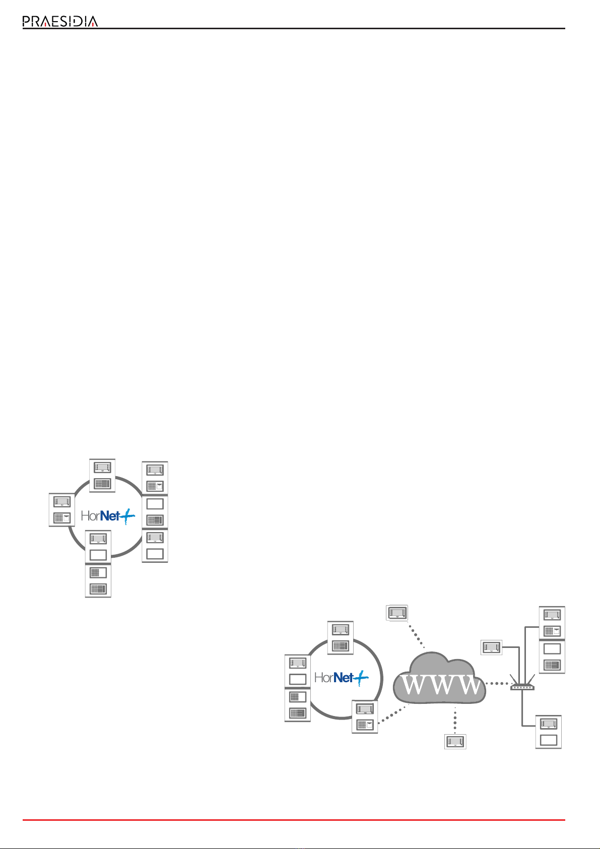
2.1 Network connection mode
The network connection of Praesidia control panels can be achieved in two ways:
Connection via a HORNET+ network
The Hornet+ network is based on an RS485 physical layer (convertible in optical
fiber by means of appropriate converters) structured in a ring. This structure
allows you to interconnect up to 48 control panels.
A group of control panels interconnected through a Hornet+ network is
identified as a “cluster”.
Connection based on TCP/IP
Use of an Ethernet connection, based on TCP/IP
protocol, as the cluster-interconnect allows you to build
up to 20 clusters.
A cluster can be made up of a single control panel or an
FPMCPU module configured as a repeater panel.
LAN
Router
Internet
Guide to networking
The Hornet+ network 7
Chapter 3
The Hornet+ network
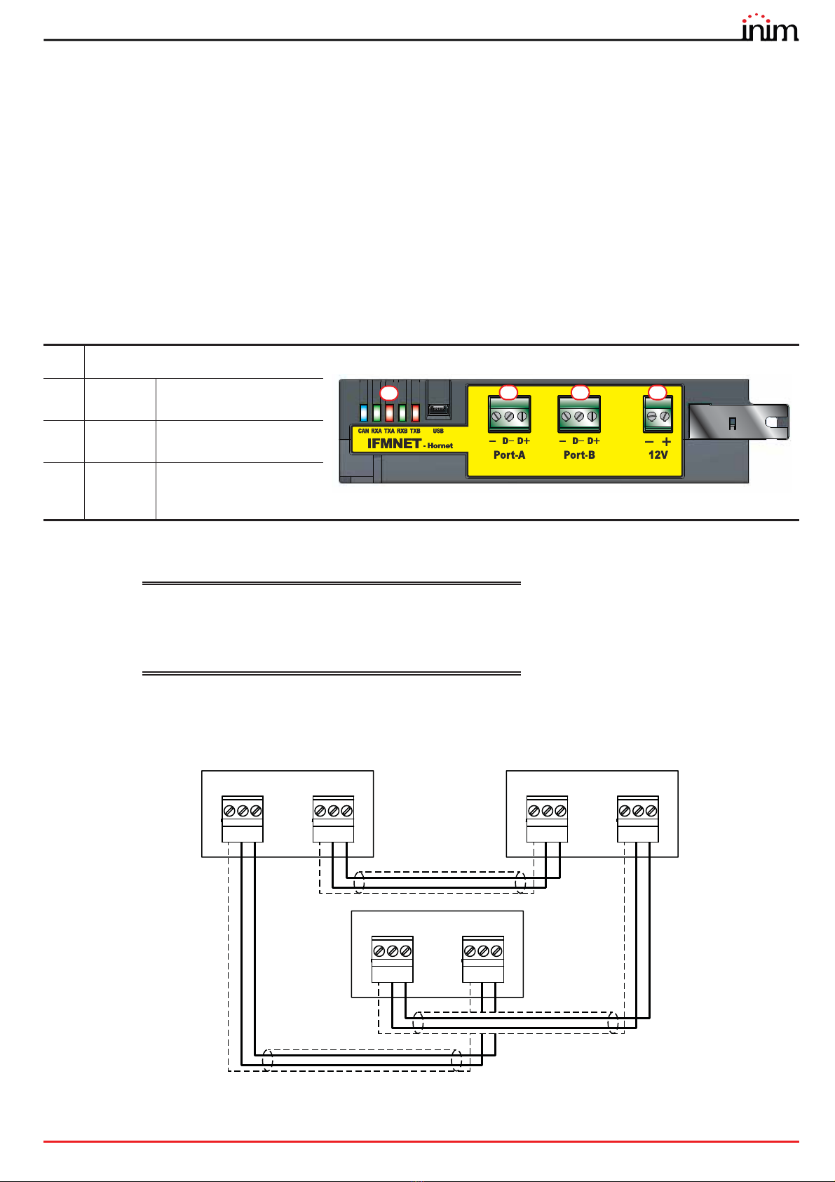
3.1 Physical layer
The connection of several control panels in Hornet+ network is based on an RS485 network, which must be structured
in ring topology in order to guarantee the appropriate fault tolerance along the cable lines.
Each control panel connected in HORNET+ network must be equipped with an IFMNET module.
The connection of two or more control panels in a Hornet+ network can be achieved by means of two RS485
communication ports ([B], [C]).
Cables: 2 wire shielded cable
Typical impedance 12Ohm
Maximum length 1000m (between two successive control
panels)
Compliant with local laws and regulations in force
The connection must be a loop connection and must respect the direction of the wiring: the terminals on the terminal
board of PORT-B must be connected with their counterparts on the terminal board of PORT-A of the next control panel;
whereas, the terminals on the terminal board of PORT-A must be connected to their counterparts on the terminal board
of PORT-B of the previous control panel.
[A] Status LED
[B] Port-A Connection terminal for
port A
[C] Port-B Connection terminal for
port B
[D] 12V
Terminals for the power
supply to the RS485/fiber
converter
AB C D
21
Port-A
3
D-
-
D+
21
Port-B
3
D-
-
D+
21
Port-A
3
D-
-
D+
21
Port-B
3
D-
-
D+
21
Port-A
3
D-
-
D+
21
Port-B
3
D-
-
D+

8The Hornet+ network
Fire detection and extinguishant system
3.2 Use of optic fiber connections
The connection of the various nodes in the HORNET+ network can be achieved through optic fiber using the
appropriate converters, as in the following example.
In cases where a fiber optic cable is used over long BUS lengths, it is necessary to use a RS485/fiber converter (non-INIM
brand product). The module IFMNET has a 12V output (paragraph 3.1 - [D]) for the power supply to the converter in use.
3.3 Supervision of the Hornet+ network
Once the Hornet+ network is configured, in the event of interruption of a single connection, each node will signal the
fault but the network will continue to function, albeit at a reduced speed.
In the event of a lost node (complete shutdown or fault on the IFMNET module) all the other nodes in the network will
signal the fault.
3.4 Commissioning of a Hornet+ network
Once several control panels have been connected in a Hornet+ network, as indicated in the diagrams shown in the
previous paragraphs, it will be necessary to work through the following points.
1. Supply power to each node in the network.
2. Configure the IFMNET module of each node in the cluster.
Work through the following points for each control panel:
2.1 Access the configuration menu
To access the configuration menu it is necessary to first access the programming phase of the control
panel () and then tap on the Configure button which appears on the screen.
Alternatively, it is possible to tap directly on the configuration status icon.
Entry of a valid access code is necessary In both cases.
21
Port-A
3
D-
-
D+
21
Port-B
3
D-
-
D+
21
Port-A
3
D-
-
D+
21
Port-B
3
D-
-
D+
21
12V
21
Port-A
3
D-
-
D+
21
Port-B
3
D-
-
D+
21
12V
12VRx/Tx 12VRx/Tx
Converter Converter
Optic fiber

Guide to networking
The Hornet+ network 9
2.2 Once the configuration menu has been accessed, the control
panel screen will provide a layout of the control panel and its parts
([A]).
Select the IFMNET module ([B]).
The module configuration section will open.
2.3 Set the communication speed to be used by the Hornet+
network.
The diagram at the side shows the theoretical maximum distances
reachable with an RS485 based on the communication baud rate/
speed.
The data refers to an ideal communication achieved through a
perfectly adapted line.
Note: The set communication speed must be the same for
all nodes in the same Hornet+ cluster).
2.4 Assign a univocal address to each node in the cluster.
The valid addresses are from 1 to 48. Address “0” is equivalent to the
disconnection of the control panel from the network.
As soon as a Hornet+ address is assigned, the IFMNET module activates the blue LED to indicate that the control panel is
in the cluster and has started to communicate with the other control panels. The LEDs on the IFMNET module indicate
activity on the two communication channels.
3. From a PC running the Praesidia-Config configuration software, you must read the network configuration in order to
have the consistent data on the PC and thus proceed with the configuration in accordance with the needs of the
installation
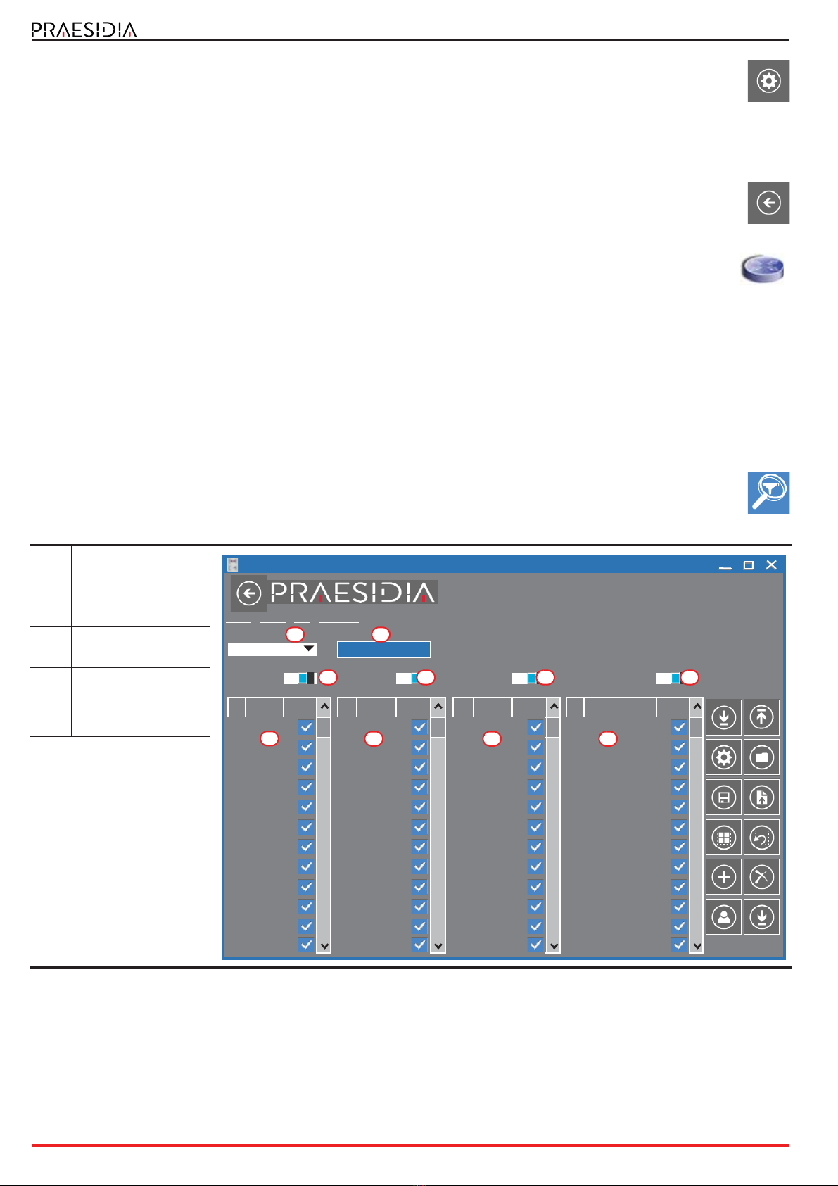
3.1 Start the Praesidia-Config.configuration software.
The interface of the Praesidia-Config software is presented in the following way:
[A] Software revision, current date
and time
[B] Button to go up to the system
layer
[C] Layer
[D] Read button
[E] Write button
[F] Settings button
[G] Control panel image
1):
1):
1):
6HW
(VF
$FFHVV
OHYHO
A
B
100K
10K 1M 10M 100
10K
1K
100
10
Cable
Length (m)
Baud rate/Speed
(Mbps)
Baud rate limit for
RS485 cabling
35$(6,',$
6\VWHP!3DQHO
G
A
CD
B
F
E
10 The Hornet+ network
Fire detection and extinguishant system
3.2 Click-on the Settings button ([F]).
In the window that opens, select the communication channel to be used for access to the control panel of
the cluster the PC is connected to (SERIAL), or to the control panel connected to the Ethernet network
intended for use as the access point to the entire cluster (IP).
- IP - if selected, you must enter the IP address and the port of the control panel. There is also a button that launches
a test on the set channel and parameters.
-SERIAL - if selected, you must select the serial port used.
3.3 Navigate to the visualization of the system at network layer using the appropriate button ([B]).
3.4 Click-on the Read button ([D]) to read the system configuration. Once the Read procedure ends, the
entire control-panel network will be shown.
The control panel the PC connected to for the read operation, and to which the "gateway" functions are
assigned, will be identified by the symbol here at the side. The control panel with this function is the one that
allows the interconnection with any other clusters via IP.
3.5 At this point it is possible to select each control panel, edit the parameters and rewrite the edited configuration
on the system by means of the Write button ([E]).
3.5 Sharing the events on the Hornet+ network
It is possible to define which events from other control panels are to be displayed for each node of the Hornet+ network
by duly configuring the Events filter section.
This section can be reached by selecting a control panel from the Hornet+ network shown on the display, and from this
by clicking-on the FPMCPU module image.
The Praesidia allows you to program up to 5 events filters through the programming section of the FPMCPU
frontplate module, by accessing the Events Filter section by means of the appropriate button.
Each event is defined by 4 categories of factors by which it is characterized:
•clustergroup
• control panel in the Hornet+ network
• zone of origin
• label (type)
In order to setup a filter, after selecting it, you must first indicate its composing events, by enabling the factors that
characterize it, that is the type and origin.
[A] Filters selection
programming field
[B] Button to change the
priority of the events
[C] Category of event
factors
[D]
Buttons to enable all
the factors of the
corresponding
category
35$(6,',$
6\VWHP!3DQHO!&38!(YHQWVILOWHU
(YHQWV)LOWHU
)LOWHU (YHQWVSULRULW\
(YHQWVUHFHLYHGIURP
6HOHFWDOO 2Q 6HOHFWDOO 2Q 6HOHFWDOO 2Q 6HOHFWDOO 2Q
1 &OXVWHU 1 3DQHO 1 =RQHV 1 /DEHO
&OXVWHU 3DQHO =RQH (9$&8$7,21
&OXVWHU 3DQHO =RQH (9$&8$7,215(67
&OXVWHU 3DQHO =RQH $/$50
&OXVWHU 3DQHO =RQH $/$505(6725(
&OXVWHU 3DQHO =RQH 35($/$50
&OXVWHU 3DQHO =RQH 35($/$505(672
&OXVWHU 3DQHO =RQD ($5/<:$51,1*
&OXVWHU 3DQHO =RQH ($5/<:$51,1*5
&OXVWHU 3DQHO =RQH 683(59,6,21
&OXVWHU 3DQHO =RQH 683(59,6,215(67
&OXVWHU 3DQHO =RQH /22323(1
&OXVWHU 3DQHO =RQH /22323(15(672
C
A B
D
C CC
DD D

Guide to networking
The Hornet+ network 11
The events coming from the network are acknowledged and shown on the display only when they satisfy all the enabled
factors of at least one of the 5 filters.
The control panel self-configures at filter n°0. This setting accepts any event, from any zone, belonging to any control
panel of any cluster, therefore, such a filter accepts all events from the entire network.
3.6 Activation of groups of outputs in the Hornet+ network
The Hornet+ system allows the activation of outputs connected to a specific network node when certain conditions are
verified on other nodes.
The configuration of such activations is possible by means of the appropriate programming of the groups of outputs.
Each of the 240 groups of each control panel can be configured as: “Hornet+ group”.
The option required is reachable via the programming section of the FPMCPU frontplate module, by accessing
the “Outputs group” section by means of the appropriate button.
Once the Hornet+ group option is activated, in the parameters section of the selected group ([B]), the group will be the
same for all the control panels in Hornet+ network. The outputs associated with the group will activate regardless of
control panel they are connected to. In the same way, the devices of any network control panel can activate the shared
group.
If you enable the Hornet+ group option on a network control panel, the software will ask if you want to share the group
with all the control panels in the network. If your answer is affirmative, the software will automatically enable the option
on all the control panels in network and on the selected group.
[A] List of groups of
outputs
[B]
Programming
parameters of the
selected group
[C]
]List of devices that
activate the selected
group
[D]
List of devices
activated by the
selected group
35$(6,',$
6\VWHP!3DQHO!&38!*URXSV
2XWSXWVJURXSODEHO
*URXS
*URXS *URXS
$FWLYDWLRQGHOD\V
$FWLYDWLRQWLPHV 3XOVH
,ILQSUHDODUPVWDWXVSDVVDXWRPDWLFDOO\WRDODUPVWDWXVDIWHUV
*URXS *URXS
+RUQHWJURXS &OXVWHUJURXS
(PHUJHQF\/DPS)XQFWLRQDO7HVW (PHUJHQF\/DPS5HVW0RGH
(PHUJHQF\/DPS%DWWHU\7HVW 1RWHVW
*URXS *URXS
'HYLFHVWKDW$&7,9$7(WKHJURXS 'HYLFHV$&7,9$7('E\WKHJURXS
*URXS *URXS
/RRS
%XWWRQ
/RRS
6PRNH'HW
/RRS
%XWWRQ /DPS /DPS /DPS
C
B
A
D

12 TCP/IP
Fire detection and extinguishant system
Chapter 4
TCP/IP
4.1 Physical Layer
To interconnect several clusters together via TCP/IP protocol, it is necessary that at least one control panel is connected
to the Ethernet network.
This control panel will be indicated as the “gateway” of the cluster and will manage information sharing among
the clusters, as well as the supervision of the TCP/IP network integrity. The icon of this control panel will show
the symbol here at the side.
If instead the icon of a control panel acquires the symbol here beside, it means it is connected to the network
with it own IP address.
4.2 Limits and precautions
The connection of several clusters via the Ethernet network is based on hardware that is not supplied by INIM
Electronics. Therefore, if the connection in the network is based on TCP/IP, it is the sole responsibility of the project
manager who designs the installation to evaluate the use made of it (supervision, display of cross events, cross
activations, etc.). Therefore, it is necessary to define the eventual characteristics of the Ethernet network, introducing,
where appropriate, switches capable of managing dual paths with automatic fault recovery capacity, wiring with different
paths, and to take all the necessary precautions to ensure that the Ethernet physical layer provides fully secure and
redundant capabilities.
4.3 Supervision of the TCP/IP network
Once the TCP/IP network has been configured, if connectivity to a cluster is lost (complete shutdown or FPMCPU
module fault) all the remaining nodes in the network will signal the fault.
4.4 Commissioning the TCP/IP network
For the configuration of a control panel network based on TCP/IP protocol, proceed in accordance with the following
points:
1. On each cluster of control panels perform the Hornet+ network setup operation (where present) as described in the
previous chapter.
2. Make sure that each cluster is equipped with an FPMCPU module
connected to the Ethernet network.
If more than one control panel per cluster is connected to the Ethernet
network, it is necessary to select the one that will serve as the gateway
to the cluster ([A]). In such cases you must make a note of the IP
addresses of each gateway.
3. Ensure that the IP address of each control panel and its net mask ([B])
are configured in such a way that they belong to the same class of
addresses as the others.
4. Using a PC, running the Praesidia-Config configuration software, connected to the same Ethernet network
and configured with a netmask consistent with the control panels, click-on the Settings button.
1HWZRUN ,3
%DFNXSSDQHO
1HWPDVN
*DWHZD\
(VF3RUW
2.
$FFHVV
OHYHO
B
A
Guide to networking
TCP/IP 13
5. Select “IP” as the communication channel and
enter the address of the first gateway on the list
([C]).
6. By means of the Check connection button ([D]) it
is possible to test the communication in order to
verify that the TCP/IP parameters TCP/IP are
configured correctly.
7. Go up through the Praesidia installation until you reach the highest layer, by means of the button on the top-
right of the window (paragraph 3.4 - [B]).
8. Click-on the Add button to add a new cluster. The software will show the new cluster,
comprising a single control panel, added to those already configured.
Repeat the operation for each cluster that you intend adding to the network.
9. For each added cluster, enter the IP address as follows:
9.1 Double click-on the control panel of the cluster.
9.2 When you reach the control panel layer click-on the Settings button.
9.3 In the window that opens, select “IP” and enter the address.
9.4 Check the communication capacity by means of the Check connection button ([D]).
9.5 Return to the “System” layer and proceed in the same way for the successive clusters.
10. Once the address has been assigned and the communication capacity tested on the gateway of each
cluster, proceed with the read operation by going up to the System layer and clicking-on the Read button.
The read operation can be simplified by indicating to the software which cluster to read, by means of the appropriate
option from the Settings window, selected on the “System” layer ([E]).
Once the read operation terminates (this operation may take several minutes depending on the size of the system), the
software will show the clusters complete with all their components. At this point the software will have read all the
elements of the network and will contain the actual data of each control panel.
However, warning icons will be shown to indicate that it is necessary to perform a write operation in order to
communicate to each component in the network the existence of all the other elements.
11. To set the programming of the entire installation click-on the Write button. This operation may take quite
some time due to the quantity of data that has to be transfered/written for each single control panel.
If you intend to write only the networking settings, you must first double click-on the network icon. In this
way you will access the Network configuration section, where you can click-on the Write button.
4.5 Sharing the events on the TCP/IP network
By appropriately configuring the Events filter section as described in paragraph 3.5 Sharing the events on the Hornet+
network, it is possible to define which events coming from other control panels are to be visualized for each node in the
network. Please refer to the said paragraph for instructions.
4.6 Activations of groups of outputs on the TCP/IP network
The Praesidia allows the activation of outputs connected to a specific node in the TCP/IP network when verified
conditions on other nodes occur.
The configuration of these activations is possible through the appropriate programming of the groups of outputs. Each
of the first 240 groups of each control panel can be configured as “Cluster group”.
The option required for this operation can be found in the programming area of the FPMCPU frontplate module,
after accessing the “Outputs group” section follow the instructions in paragraph 3.6 Activation of groups of
outputs in the Hornet+ network.
Once the Cluster group option is enabled, available in the parameters section of the selected group, the group
programmed in this way will be the same for all the control panels connected in the TCP/IP network. The outputs
associated with the group will activate regardless of control panel they are connected to. In the same way, the devices of
any network control panel can activate the shared group.
&RPPXQLFDWLRQ 9DULRXV
&RPPXQLFDWLRQFKDQQHOFOXVWHU[[[ &RQWUROSDQHO\\\
7\SHRIFRQQHFWLRQ
,3 ,3 &KHFNFRQQHFWLRQ
3RUW
6(5,$/ 6HULDOSRUW
*$7(:$<
5HDG:ULWHVHWWLQJV &OXVWHU]]]
C
D
E

14 Repeater based on TCP/IP
Fire detection and extinguishant system
Chapter 5
Repeater based on TCP/IP
If you intend to configure a Praesidia control-panel repeater on a TCP/IP network, it is necessary to have an FPMCPU
module.
After proper installation of the module, you must connect the Ethernet cable then proceed with the configuration
process, first via the repeater touch screen then, successively, via the Presidia-Config programming software.
Via the display
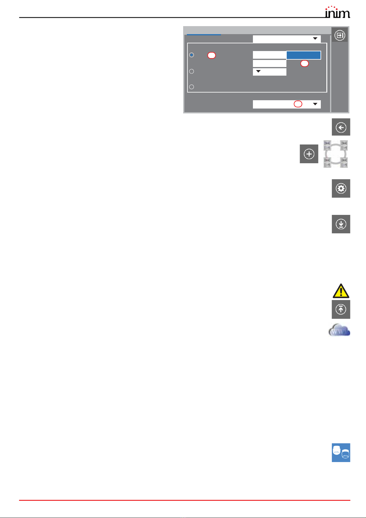
First of all you must assign an IP address to the repeater:
1. Press the Programming button on the home page of the display and
enter an access code valid for level 3 (code “00004” at default)
2. Access the Network section and assign a valid IP address ([A],
192.168.1.121 at default).
3. Press the OK button [A] to exit and save.
After doing so, it is necessary to check that the address of the repeater is “0”.
To do this it is necessary to access the Programming section, as indicated
above, then access the Configuration section.
The configuration process continues through the control pane programming software.
Via Praesidia-Config
To configure an IP repeater, it is necessary to start from a solution that already exists.
1. Go up to the “System” section [A] and
click-on the Add button [B].
2. On the window that opens, double click-
on the repeater icon. The repeater will be
added at the side of the first cluster in the
top part of the section [C].
The warning icons [D] inside clusters 1 and 2
indicate that it is necessary to perform a write
operation in order to communicate to each
component in the network the existence of
the other elements.
Therefore, you must select the type of
communication connection with the
repeater.
3. Click-on the icon of the repeater [C] and
then on the Settings button [E]. The
respective window will open.
1HWZRUN ,3
%DFNXSSDQHO
1HWPDVN
*DWHZD\
(VF3RUW
2.
$FFHVV
OHYHO
B
A
35$(6,',$
6\VWHP
&OXVWHU &OXVWHU
&OXVWHU
C
B
A
E
D
D

Guide to networking
Repeater based on TCP/IP 15
4. Select “IP” as the communication channel and enter
the IP address of the repeater and the
communication port (6001) [F]..
5. The Check connection button [G] will allow you to
test the communication and verify that the TCP/IP
network parameter are configured correctly.
At this point you must associate the repeater
with a control panel.
6. Access the repeater programming screen
by double clicking-on the respective icon
and perform a read operation using the
Read button [H].
7. Select, in the respective programming
fields [I], the cluster and the control panel
you want to associate the repeater with.
8. Using the [J] button, return to the
“System” section. You will note that the
icon of the repeater is positioned at the
side the cluster it is associated with.
9. Access the “Network Configuration” section by double clicking-on the icon in the centre of the
window.
10. In the clusters list on the left [K], the
“Gateway not defined” message will
be shown in the field corresponding
to the repeater being configured.
Click on the “Gateway not defined”
message to open a dropdown
menu where you can select an IP
address for the repeater.
11. In the same list, first click-on the
cluster the repeater is associated
with [L] and then on the relative
control panel underneath [M].
12. In the column on the right, in the
row of the cluster the repeater is
associated with [N], check that the
cluster and the control panel (you
want to associate the repeater with)
are correct.
13. Click-on the Write button [O].
If everything is correct, all the control panels in the network and their relative IP repeaters will go into programming status.
&RPPXQLFDWLRQ 9DULRXV
&RPPXQLFDWLRQFKDQQHOFOXVWHU &RQWUROSDQHO\\\
7\SHRIFRQQHFWLRQ
,3 ,3 &KHFNFRQQHFWLRQ
3RUW
6(5,$/ 6HULDOSRUW
*$7(:$<
5HDG:ULWHVHWWLQJV &OXVWHU]]]
F
G
35$(6,',$
6\VWHP!3DQHOGLVSOD\
5HDFWLYDWHVLOHQFHGVRXQGHUVDI
(YDFXDWLRQEXWWRQPRGH
(YDFXDWLRQDWOHYHO
'RQRWXQGR6LOHQFHPRGHRQQHZDODUP
2Q
,QVWDQWDODUPRQVHFRQGSUHDODUP
2II
%X]]HUVLOHQFHG
2Q
/RFNUHVHWWLPHDIWHUH[WLQFWLRQPLQ
5HIHUHQFHFOXVWHU
&OXVWHU
5HIHUHQFH&RQWUROSDQHO
&RQWUROSDQHO
\\\
H
I
J
35$(6,',$
6\VWHP!1HWZRUN&RQILJXUDWLRQ
&RQWUROSDQHOODEHO &RQWUROSDQHO
5HRUJDQL]H1HWZRUN ,3
3RUW &RQWUROSDQHO
&OXVWHU +RUQHWJDWHZD\ 1HWPDVN &RQWUROSDQHO
&OXVWHU 3DQHO[ &OXVWHU &RQWUROSDQHO
&OXVWHU 3DQHO\
&OXVWHU5HSHDWHU,3 3DQHO] 1 /DEHO ,3 &OXVWHU 3DQHO
&OXVWHU
&OXVWHU
&RQWUROSDQHO[ &RQWUROSDQHO]
&OXVWHU
&OXVWHU
&OXVWHU
&RQWUROSDQHO\ 5HSHDWHU\
&OXVWHU
O
K
M
L
N
DCMNINE0PRAESIDIA-100-20170310

18
Fire detection and extinguishant system
Centobuchi, via Dei Lavoratori 10
63076 Monteprandone (AP) Italy
Tel. +39 0735 705007 _ Fax +39 0735 704912
ISO 9001 Quality Management
certified by BSI with certificate number FM530352
Table of contents
Other INIM Electronics Fire Alarm manuals


Popular Fire Alarm manuals by other brands


Ampac
Ampac FireFinder II Series Installation & operation manual

Notifier
Notifier AFP-300 Programming manual

Mircom
Mircom MS-700ID SERIES operating instructions

Wheelock
Wheelock MB Series installation instructions

Honeywell
Honeywell NOTIFIER FireWarden-100-2 instruction manual

Fire-Lite Alarms
Fire-Lite Alarms MS-9200 Technical manual


