Fiberplex TTM User manual
USERMANUAL
6PositionTrussMountEnclosureforTDSeries
Moduleswith16ChannelModularFrontPanel
TTM

WarningforYourProtection
1.Readtheseinstructions.
2.Keeptheseinstructions.
3.Heedallwarnings.
4.Followallinstructions.
5.Donotusethisapparatusnearwater.
6.Cleanonlywithadrycloth.
7.Donotblockanyoftheventilationopenings.Installinaccordancewiththemanufacturer’sinstructions.
8.Donotinstallnearanyheatsourcessuchasradiators,heatregisters,stoves,orotherapparatus(includingamplifiers)thatproduceheat.
9.Donotdefeatthesafetypurposeofthepolarizedorgrounding‐typeplug.Apolarizedplughastwobladeswithonewiderthantheother.A
groundingtypeplughastwobladesandathirdgroundingprong.Thewidebladeorthethirdprongisprovidedforyoursafety.Iftheprovidedplug
doesnotfitintoyouroutlet,consultanelectricianforreplacementoftheobsoleteoutlet.
10.Protectthepowercordfrombeingwalkedonorpinched,particularlyatplugs,conveniencereceptacles,andthepointwheretheyexitfromthe
apparatus.
11.Onlyuseattachments/accessoriesspecifiedbythemanufacturer.
12.Useonlywiththecart,stand,tripod,bracket,ortablespecifiedbythemanufacturer,orsoldwiththeapparatus.Whenacartisused,use
cautionwhenmovingthecart/apparatuscombinationtoavoidinjuryfromtip‐over.
13.Unplugthisapparatusduringlightningstormsorwhenunusedforlongperiodsoftime.
14.Referallservicingtoqualifiedservicepersonnel.Servicingisrequiredwhentheapparatushasbeendamagedinanyway,suchaspower‐supply
cordorplugisdamaged,liquidhasbeenspilledorobjectshavefallenintotheapparatus,theapparatushasbeenexposedtorainormoisture,does
notoperatenormally,orhasbeendropped.
Theapparatusshallnotbeexposedtodrippingorsplashing.Noobjectsfilledwithliquids,suchasvasesordrinkcups,shallbeplacedonthe
apparatus.
“WARNING:Toreducetheriskoffireorelectricshock,donotexposethisapparatustorainormoisture.”
GeneralInstallationInstructions
Pleaseconsiderthesegeneralinstructionsinadditiontoanyproduct‐specificinstructionsinthe“Installation”chapterofthismanual.
Unpacking
Checktheequipmentforanytransportdamage.Iftheunitismechanicallydamaged,ifliquidshavebeenspilledorifobjectshavefallenintothe
unit,itmustnotbeconnectedtotheACpoweroutlet,oritmustbeimmediatelydisconnectedbyunpluggingthepowercable.Repairmustonlybe
performedbytrainedpersonnelinaccordancewiththeapplicableregulations.
InstallationSite
Installtheunitinaplacewherethefollowingconditionsaremet:
Thetemperatureandtherelativehumidityoftheoperatingenvironmentmustbewithinthespecifiedlimitsduringoperationofthe
unit.Valuesspecifiedareapplicabletotheairinletsoftheunit.
Condensationmaynotbepresentduringoperation.Iftheunitisinstalledinalocationsubjecttolargevariationsofambient
temperature(e.g.inanOB‐van),appropriateprecautionsmustbetaken.
Unobstructedairflowisessentialforproperoperation.Ventilationopeningsoftheunitareafunctionalpartofthedesignandmust
notbeobstructedinanywayduringoperation(e.g.‐byobjectsplaceduponthem,placementoftheunitonasoftsurface,or
improperinstallationoftheunitwithinarackorpieceoffurniture).
Theunitmustnotbeundulyexposedtoexternalheatsources(directsunlight,spotlights).
AmbientTemperature
UnitsandsystemsbyFiberPlexaregenerallydesignedforanambienttemperaturerange(i.e.temperatureoftheincomingair)of+5...+40°C.
Whenrackmountingtheunits,thefollowingfactsmustbeconsidered:
Thepermissibleambienttemperaturerangeforoperationofthesemiconductorcomponentsis0°Cto+70°C(commercial
temperaturerangeforoperation).
Theairflowthroughtheinstallationmustallowexhaustairtoremaincoolerthan70°Catalltimes.
Averagetemperatureincreaseofthecoolingairshallbeabout20C°,allowingforanadditionalmaximum10C°increaseatthe
hottestcomponents.
Ifthecoolingfunctionoftheinstallationmustbemonitored(e.g.forfanfailureorilluminationwithspotlamps),theexhaustairtemperaturemust
bemeasureddirectlyabovethemodulesatseveralplaceswithintheenclosure.
GroundingandPowerSupply
Groundingofunitswithmainssupply(classIequipment)isperformedviatheprotectiveearth(PE)conductorintegratedinthreepinPhoenix™
connector.Unitswithbatteryoperation(<60V,classIIIequipment)mustbeearthedseparately.Groundingtheunitisoneofthemeasuresfor
protectionagainstelectricalshockhazard(dangerousbodycurrents).Hazardousvoltagemaynotonlybecausedbydefectivepowersupply
insulation,butmayalsobeintroducedbytheconnectedaudioorcontrolcables.
Thisequipmentmayrequiretheuseofadifferentlinecord,attachmentplug,orboth,dependingontheavailablepowersourceatinstallation.If
theattachmentplugneedstobechanged,referservicingtoqualifiedpersonnel.

Warranty,ServiceandTermsandConditionsofSale
ForinformationaboutWarrantyorServiceinformation,pleaseseeourpublished‘TermsandConditionsof
Sale’.Thisdocumentisavailableonfiberplex.comorcanbeobtainedbyrequestingitfrom
[email protected]orcalling301.604.0100.
Disposal
DisposalofPackingMaterials
Thepackingmaterialshavebeenselectedwithenvironmentalanddisposalissuesinmind.Allpackingmaterial
canberecycled.Recyclingpackingsavesrawmaterialsandreducesthevolumeofwaste.Ifyouneedto
disposeofthetransportpackingmaterials,recyclingisencouraged.
DisposalofUsedEquipment
Usedequipmentcontainsvaluablerawmaterialsaswellassubstancesthatmustbedisposedof
professionally.Pleasedisposeofusedequipmentviaanauthorizedspecialistdealerorviathepublicwaste
disposalsystem,ensuringanymaterialthatcanberecycledhasbeen.Pleasetakecarethatyourused
equipmentcannotbeabused.Afterhavingdisconnectedyourusedequipmentfromthemainssupply,make
surethatthemainsconnectorandthemainscablearemadeuseless.
Disclaimer
Theinformationinthisdocumenthasbeencarefullycheckedandisbelievedtobeaccurateatthetimeof
publication.However,noliabilityisassumedbyFiberPlexforinaccuracies,errors,oromissions,norforlossor
damageresultingeitherdirectlyorindirectlyfromuseoftheinformationcontainedherein.

Introduction
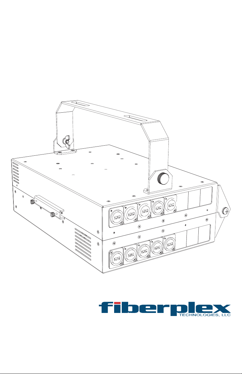
ComplementingtheflexibilityoftheFiberPlex‘TDSeries’offiberopticmodules,theTTMprovidesconnection,
mounting,power,andcablemanagementforupto6frontfacingTDmodulesinacompactandruggedTruss
Mountablealuminumenclosure.Eachofthe16channelsofthemodularTTMfrontpanelcanaccommodate
anyNeutrik™DSeriesconnector,LCandSTbarrelconnectors,DB9connectors,etc.Theunusedpositionsare
simplyfilledbyinsertingblankpanels.Additionally,theTTMhas4additionalmodularchannelsontherearof
theunitforgreaterflexibility.Therearconnectorsallowforcableattachmentinopposingdirectionswithout
worryingaboutbendingthefiber‐opticcables,whilealsohelpingtokeepthecablingneatandorganized.The
integratedkey‐holemountingholesonthebottomoftheTDunitslocksecurelyonmatingstudswhilearear
retentionbarholdsthemsecurelyinplace.A6positionpowerwiringharnessandincludedpoweradapter
providepowerandapositiveearthgroundtothemodulesvia3positionPhoenix™lockingpowerconnectors.
Managingallthatcablingandfibercanbetedious;theTTMallowsasimplesolutiontoputmaximumcapacity
andflexibilityintoasingletrussmountedunit.
KeyFeatures
Providesmountingandpowerforupto6singlewideTDSeriesmodules,orupto2
doublewideand2singlewidemodules
Perfectforconnectingtotrussmountedequipment
Accommodatesupto16connectorpositions
PlatesavailableforstandardNeutrik™DSeriesconnectors,LCandSTbarrels,DE‐9,etc
Reconfigureinminutes
Securelyseatsmoduleswithpositiveretentionbar
IntegratedACpowersupplyandwiringharnessincluded
Convenientcabletrayforcleaninstallation
GettingStarted
InitialInspection
Immediatelyuponreceipt,inspecttheshippingcontainerfordamage.Thecontainershouldberetaineduntil
theshipmenthasbeencheckedforcompletenessandtheequipmenthasbeencheckedmechanicallyand
electrically.Iftheshipmentisincomplete,ifthereismechanicaldamage,oriftheunitfailstooperatenotify
FiberPlexandmaketheshippingmaterialsavailableforthecarrier'sinspection.
ChassisMounting
TheTTMcanbeopenedbyunscrewingthetwothumbscrewsalongthelatch,andswingingthechassisopen
aboutthehinges.Topreventpinchinginjury,keepfingersawayfromtheopenedgeswhenclosingthechassis.
Mountthechassistoanystandardtrusssectionusingtwotrussclamps,alsoknownasCheeseboroughclamps,
(notincluded)oftheappropriatesize.TheTTMmountingbracketisdesignedtoaccommodatetrussclamps
withM10mountingbolts.Theseclampsshallbeaffixedtotheswivelbracketofthechassis,withtheM10
mountingboltthrougheachslot.Therotationalalignmentcanthenbeadjustedbylooseningthetwowing
nutswherethebracketjoinsthechassis,movingtheTTMtothedesiredposition,andthentighteningthe
wingnutsandthetrussclampstoholditinplace.Thechassisshouldbelocatedinanenvironmentwherean
ambienttemperaturebetween0°and50°Ccanbemaintained,withallventsunobstructed.
PowerRequirements
Anycombinationof6FiberPlexTDSeriesModulescanbemountedinaTTM.EachTDmodulecandrawas
muchas6Watts,andtheventilationfancandrawupto1.5Watts,foratotalmaximumpowerconsumption
of37.5Watts.Powerissuppliedtotheindividualmodulesthroughapre‐wiredPowerHarnessthatconnects
theonboardpowersupplytothemodulesusing3pinPhoenix™connectors.PowerissuppliedtotheTTMas
ACmainspower(100to240V,universal)throughaNeutrikPowerCONTRUE1connectorontherearofthe
enclosure.
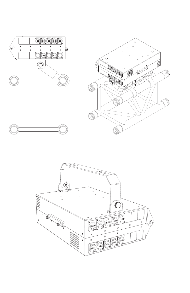
MountingOptions
Figure1TrussMountusingCheeseboroughClamps(notincluded)
Figure2Portable"DropBox"

Features
Figure3:TTMOpen
TTMEnclosure–ThehingedtraysoftheTTMaremadefromruggedaluminumandneatlyfoldclosed,
givingitalowprofilewhilemountedtoatruss.Theunithas6pairsofstudspressedintothebaseto
matewiththekeyholesonTD‐Seriesmodules.
FiberPlexTD‐SeriesModules(NotIncluded)–TheTTMcanaccommodateupto6TD‐Seriesmodulesor
twodouble‐widemodulesandtwoadditionalsingle‐widemodules.
RetentionBar& RetentionScrews–OncetheTD‐Seriesmodulesaresecurelyseatedonthe
pressedstuds, theretentionbarslidesinbehindthemtosecurethemodulestightlyinplace.
Tworetentionscrewsarethentightenedtoholdthebar.
CableTieDown–Sixtie‐wrapbasesareaffixedwithintheenclosuretoallowforcleanmanagementof
cablingtotheTD‐Seriesmodules.Tie‐wrapscanbeusedtosecurecablebundlesagainsttherearand
insidehingefacetopreventpinchingofthecablewhenclosingtheassembly.
BackShellRelief–ThebarprovidesclearancenotchesforthePhoenix™backshellsinstalledonthe
wiringharnessorindividualpowerconnections.Thesereliefcutsalsoeaseinsertionofthepower
connectionswhiletheretentionbarisinplace.
PowerSupplyBox–TheAC‐DCconverter,agroundpin,andtheACwiringarecompletelycontained
withinthepowersupplyboxtopreventelectrocution.Thishigh‐efficiencypowerunitcansupplyenough
powertorunallsixTDmodulesatfullloadandprovidesover‐current,over‐voltage,andshortcircuit
protection.
1
14
2
5
7
12 11
9
3
10
13 6
15 16
1
2
3 4
6
5
7
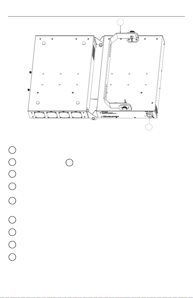
Figure4TTMOpen,Bottom
PowerCONTRUE1Connector–ACpowerentryfortheunit.Thisconnectormateswithastandard
PowerCONACplugtoreceiveinputpowerwithaflexiblevoltagerangeof100to240VAC.
PowerHarnesswith(6each) Phoenix™PowerConnectors–TheTTMcomesstandardwitha6‐
positionwiringharness.This harnessreceivesitspowerfromtheintegratedpowersupply.
ConnectorPositionBlankingPlates–Theseplatesfillunusedconnectorspaceinthefrontoftheunit.
I/OConnectorPositions–InputandOutputconnectorstotheTD‐Unitsareprovisionedhere.
RearConnectorPlates–Theunitcanbeequippedwithupto4I/Oconnectorsintherear,allowingfor
easybidirectionalconnection.Pleasenotethattheseplatesaredifferentlysizedandnotinterchangeable
withthefrontI/Oconnectorplates.
EnclosureLatch–Theunitissecurelyclosedscrewingthetwocaptivescrewsinthelatchbracketinto
holesontheoppositeenclosurehalf.
Hinge–Thereinforcedaluminumhingesallowtheunittosmoothlyswingopenforeasyserviceand
reconfiguration,andswingclosedforacompactprofileduringuse.
VentilationFan–Theunitcomesequippedwithaquietrunning50mmfantoremoveanyexceess
heatedairinsidetheenclosure.
Swivelbracket–Attachedtotheenclosureisaswivelablemountingbracket.Trussclampsaremounted
inthetwoslots.Theswivelpositionofthebracketcanbeadjustedbylooseningthethumbscrews,then
squeezingthetwosidestogethertofreethepositioningpins.Whilesqueezing,rotatethebracketintothe
desiredposition,thenletgoandtightenthethumbscrews.Optionally,wingnutscanbescrewedontothe
thumbscrewsandjammedagainstthemountingbracketthreadstoprovidevibrationresistance.
8
17
8
9 10
11
12
13
14
15
16
17

InstallingTDModules
1. OrienttheTDSeriesmodulewiththerear
(powerside)facingtherearoftheTTM
2. Alignthelargeopeningofthekeyholeonthe
bottomtotheTDmodulewiththepressed
studsontheMountingTray
3. LowertheTDmoduleoverthestudsuntilthe
moduleisflatonthetrayandslidetothefront
oftheMountingTrayuntilthemodulestops
4. Repeatsteps1‐3untilalldesiredmodulesare
installed.
5. LowertheRetentionBarflatonthetraysothat
itisontherear(power)sideoftheTDmodules
andstraddlesthethreadedstandoffs
6. PushtheRetentionBarforwarduntilitissecure
againsttheTDmodules,thereshouldonlybea
tinyshiftasittightensagainsttheunit.Tighten
theRetentionScrews.Repeatsteps5and6for
thethreemodulesontheotherhalfofthe
enclosure.

7. ConnectthePhoenix™powerconnector
fromthePowerHarnessatintoitsmating
connectorontheTDmoduleineach
position.
8. InstallloadedTTMontotrusswith
appropriateCheeseboroughclamps.
ReconfiguringFrontConnectors
1. Unscrewandremovetheupperpositioningand
holdingbracketsbyremovingthe7retainingscrews.
Notethatthescrewthatprotrudesthroughthehinge
bracketisslightlylongerthantheothers.
2. Slightlyloosenthe4screwsholdingthebottommountingplatetoreleasethe
modularconnectorplates.
3. Replaceandrearrangeconnectorplatesasneeded,
takingcaretoorientthechamferededgestowards
thefrontoftheenclosure.
4. Replaceandtheupperpositioningbracketusingtwoscrewsas
shown.
5. Tightendownthescrewswhichholdthelowerholdingbracket.
6. Replacetheupperholdingbracketandtightenall
screws.

Specifications
Figure5TTMDimensions,CaseOpen
20.65
[524.6]
21.48
[545.5]
2.78
[70.7]
1.81
[46.0]
14.28
[362.6]
Table of contents


