Chziri ZVFG7 series User manual

ZVFG7 SERIES
ϵÁÐ
ZVFP7 SERIES
ϵÁÐ
³¬Ì©µçÆ÷
INVERTER USER'S MANUAL
ÉϺ£³¬Ì©µçÆ÷ÓÐÏÞ¹«Ë¾
INVERTER

Foreword
Thank you very much for your purchase of ZVFG7
and ZVFP7 series of inverters.
This manual introduces the installation, operation,
function setting, trouble shooting and etc. of inverters.
Ensure that this manual is made available to the final
user and keep it handy for future reference.
If there is any doubt or question, please contact the
Technical Service Center of Company.
Incorrect installation or use may result in damage or other
accidents. Do read all instructions in detail before installing
or operating.

Directory
Article 1.Safety Instruction 4
1.1 The indication of safty symbol 5
1.2 Caution of electric 5
1.3 Caution of Installation and connection item 5
1.4 Caution of Operation 6
1.5 Caution of enviroment 7
Article 2 Introduction to Products 8
2.1 Checking after you got the Inverter 9
2.2 Symbol andtype reference 9
2.3 specification 10
2.4 standard technique 11
Article 3 Installation and Connection 12
3.1 Installation of Inverter 13
3.2 Connecting of Inverter 14
Article 4 Control panel and display 21
4.1 Control panel 22
4.2 Operation of control panel 24
4.3 The content of dispay 27
Article 5 Run-in test 28
5.1 Run-in test 29
5.2 Operation of run 30
Article 6 Reference on Function Data 31
6.1The fleet of function data 32
6.2Detail reference of function data 39
Article 7 Trouble diagnosis and treatment 58
7.1Trouble and the reason 59
7.2 Familiar trouble diagnosis and treatment 60
7.3Motor abnormity and treatment 64
Article 8 Repairing and Maintenance 66
8.1Repair and maintain 67
8.2 Transport and deposited 68
Article 9 Exterior dimension and installing dimension
69
9.1 Exterior dimension and installing dimension 70
Directory
Article 10 Quality guarantee 72
10.1Quality guarantee 73
Appendix
Appendix AOperation panel 74
Appendix B Trig unit .brake resistance 75
Appendix C Reference of surrounding equipment 76

1.1
1.2
1.3
1.4
1.5
1.1
1.2
1.3
Indications of Safety Symbols 5
Cautions for Electrical Work 5
Cautions for Installing and Wiring 5
Cautions for Operation 6
Cautions for Working Ambient 7
Article 1
This article mainly introduces cautions for installation, wiring,
operation, operating conditions and electrical work. To avoid
any errors that may result in damage to equipment or injury to
personnel, do read carefully all of the instructions in this article.
Indications of Safety Symbols
To use and operate the inverter correctly, do read and clearly understand
the following symbols in this manual before installing and operating it, and
follow the instructions exactly.
WARNING: This symbol callsyour attention toavoid any incorrect
operation that can result in serious damage to the
equipment or death to personnel.
CAUTION:This symbol callsyour attention toavoid any incorrect
operation that can result in damage to the inverter or
other equipment.
Caution of electric
The ground terminal must be reliably, properly and independently grounded
to ensure security.
The electronic components inside the inverter arevery sensitive to static.
Do keep your hands off thecircuit board and never put foreign matter inside
the inverter before taking antistatic measures. Otherwise, there is an
equipment failure.
Do not touch any active components in the inverter, for high voltage remains
in it when the indicator light isON after the power cut.
Cautions for Installation and connection
The installation and connection of inverter should be operated by qualified
electricians. Read this instruction manual in detail before installing and wiring.
Wait at least five (5) minutes after turning OFF the power supply before wiring.
Otherwise, there is the danger of electricshock.
Be sure that the main circuit iscorrectly wired. Three-phase 200V or 400VAC
input power must be connected to the terminals labeled R, S and T. Single
phase input power must be connected to terminals labeled L1 and L2. The
output power should be connected to terminals marked U, V and W. Otherwise,
there is serious damage to the inverter.
The output terminals (U, V, W) should be connected to the motor directly. Do
not install electromagnetic contactor, switch, capacitor or surge suppressor
between the terminal and the motor.Otherwise, it may result in inverter failure
and device damage.
Be sure to install the inverter on flame-resistant material such as a steel plate,
for heat will be produced during the running ofinverter. The surfaceof plate must
be flat or even. Otherwise, the base of inverter might be easily broken.
Be sure to install an exhaust fanor other ventilation equipment in the casein
which the inverter is installed, so as to keepthe ambient temperature less
than +40 .
Safety Instruction
Article 1 Safety Instruction

1.4 1.5
Cautions for Operation
Be sure to turn ON the input power supply only after closing the case. While
the inverter is energized, be sure not to open the case. Otherwise, there is the
danger of electric shock.
Be sure not to operate the inverter with wet hands. Otherwise, there is the
danger of electric shock.
Be sure not to disconnect power or install an electromagnetic contactor between
inverter and power to start or stop the inverter. Otherwise, it could reduce the
service life of inverter.
If the Retry Mode is set, please put a warning sign like KEEP CLEAR in
an eye-catching place before the equipment to avoid sudden restart of the
equipment after a trip stop that may result in injury to personnel.
Set an appropriate status of forward orreverse according to your specific
requirements. Otherwise, the motor may counter rotate.
Do not modify the set parameter value for inverter if there is no special
requirement, for the factory default setting has been done properly. Otherwise,
it may cause damage to the inverter or equipment due to error parameter.
The heat sink base, the braking resistanceand other heating elements will
have high temperature in running. Be carefulnot to touch them.
The operation of inverter can be easily changed from low speed to high speed.
Be sure to check the capability and limitations of the motor before operating the
inverter. Otherwise, the motor may get burned.
Cautions for operating ambient
It is strongly recommended not to use the
inverter in the following places that have:
direct exposure
to sunlight
corrosive gas
and liquid
Salt
gasoline and air mist
high humidity with relative
humidity>90% or dew
condensation
iron dust or foam
strong vibration extreme cold
over heat
Electromagnetic
wave (i.e., Welding
machine)
radioactive material
flammable material
Article 1 Safety InstructionArticle 1 Safety Instruction

2.1
2.2
Z VF 7
G
P
2 022
4
015
015=1.5kw
Introduction to Products
Article 2
Check the inverter immediately after you get it 9
Instruction on the nameplate and type 9
Product Specifications 10
Standard Technical Specifications 11
2.2.1 Instruction on the nameplate 9
2.2.2 Instruction on the nameplate 9
This article is a brief introduction of Inverter,main items
are name plate reference.type reference,the gerneral technique
and the checking item after you got the Inverter.
Checking after you got the Inverter
The Inverter has been inspected strictly and keep the Inverter
shock resistent.crash resistent ,maybe the accident happened in the
transport,so please open the carton and check it as soon as you got the
products.
Checking item:
1. check theInverter destroied or not.
2. Packing box concluding a piece of Inverter,a brochure.
3. Check the name plate ,be sure that the Inverter is your ordered.
The reference of name plate and type
2.2.1 Reference ofname plate
MODEL: ZVFG7-4015 1.5KW 2HP
INPUT: 3PH 400V 50/60Hz
OUTPUT: 3PH 0-400V 3.7A
Freq. Range: 0-400Hz
S / N: 0408001
AC Motor Drives Model.
Input Spec.
Output Spec.
Freq .Range.
Seri No. Bar Code.
2.2.2 Reference oftype
Maimum motoradapter power:022=2.2k w
Voltage ofinput:2=200v
4=400v
The code ofdesign
G means typeof ventilating(constant angular force)
P means typeof fan drive .water pump(square angularforce)
Converter adjustment
Code of enterprise
Article 2 Introduction to Products
S stands for single phase input, and
T stands for three-phase input.
S/T
INVERTER
2.3
ZVFG7-2015T/S
ZVFG7-2022T/S
ZVFG7-4007T
ZVFG7-4015T
ZVFG7-4022T
ZVFG7-4037T
ZVFG7-4055T
ZVFG7-4075T
ZVFG7-4110T
ZVFG7-4150T
ZVFG7-4185T
ZVFG7-4220T
ZVFG7-4300T
ZVFG7-4370T
ZVFG7-4450T
ZVFG7-4550T
ZVFG7-4750T
ZVFG7-4930T
ZVFG7-41100T
1.5
2.2
0.75
1.5
2.2
3.7
5.5
7.5
11
15
18.5
22
30
37
45
55
75
93
110
7
10
2.5
3.7
5
8.5
13
18
24
30
39
46
58
75
90
110
150
170
210
2.4
0 30%
0.0 5.0 Hz
1 12KHz
IP20
Product Specifications
220
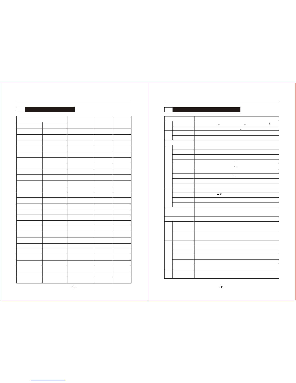
Standard Technical Specifications
Input
Item Reference
Input voltage
Input frequency
Output voltage
Output frequency
Single phrase 200V +15% three phrase 400V+20%
50/60 Hz+5%
Three phrase 0~inputvoltage
0.1~400Hz
Campacity of overload
ZVF-G7:150%rated current one minute ZVF-P7:
120%Rated current one minute
Control function
Adjustment
Output Accuracy
Space voltage complexor SVPWM control
Max output frequency +0.1%
Output frequency
resolution factor
Data setting:0.1Hz analog setting:Max frequency *0.1%
angular force lifting
angular force
compensation
Speed/release time
PWM carrier frequency
V/F curve line
Mutistep run
Straight and S curve line .eight section
speed/release the time.set range 0.1~999.9s
Set the V/F curve arbitrarily
DC brake frequency 0.0~25.0Hz.torque 0~30%.time 0.0~25.0S
Run function
Run control
Frequency setting
Input signal
Output signal
Panel control .terminal control exterior
Panel key ,analog voltage or potentiometer .
analog current .terminal exterior lift/down
Positive. Reverse command,multi speed command,run command,
accident input,reset command,count input and so on.
Accident warning output (250V/2A contact),open electric pole output
Other function Diagram run.PID.restart after transient stop,restart after accident,
frequency down up,data locking.crawl function.absorbing function and so on.
Protection function
Overcurrent protection.over voltage protection.under voltage protection.
overload protection.over heat protection.output short circuit protection
Dispaly
Run
accident
Output frequency.output current.output voltage.DC bus bar voltage.speed .
PID feedback.PID aim data.counter data
Overc urrent.over voltage.under voltage.overload.over heat.output shirt
circuit.system abnormality.fault of diagram code.accident exterior.depsoit
fault.data fault and so on
Enviroment
Exterior connecting meter
Work place
altitude
Temperature.humidity
shake
Deposit temperature
Analogue frequency teller.analogue ammeter(ImA).analogue volmeter(DC10V)
Indoor,avoid the sunshine,without dust ,without combustible and corrosion gas
Below 1000 meters
Temperature:-10 degree~+40 degree humidity:20%~90%RH(with water drip)
Below 0.5G
-20 degree~+60 degree
Force fan cold
Function
Protect grade
Manner of cooling
ZVFP7-4110T
ZVFP7-4150T
ZVFP7-4185T
ZVFP7-4220T
ZVFP7-4300T
ZVFP7-4370T
ZVFP7-4450T
ZVFP7-4550T
ZVFP7-4750T
ZVFP7-4930T
ZVFP7-41100T
ZVFG7-2037T/S
ZVFG7-2055T
ZVFG7-2075T
ZVFG7-2110T
ZVFG7-2150T
ZVFG7-2185T
ZVFG7-2220T
3.0 13
Output
Article 2 Introduction to ProductsArticle 2 Introduction to Products
Three-phase 200V 15%
220
220
220
Type of Inverter
Input Voltage
(v)
Max Adapter
Moter(kw)
Rated output
current(A)
ZVFG7-2007T/S 0.75 4
220
means type of
ventilating
means type of fan
drive .water pump
220
220
220
220
220
380
380
380
380
380
380
380
380
380
380
380
380
380
380
380
380
380
5.5
7.5
11
15
18.5
22
33
65
75
90
49
25

3.1.1
3.1.2
3.1.3
3.2.1
3.2.2
3.2.3
3.2.4
3.1
3.2
3.1
150mm above
150mm above
50mm above 50mm above
1 2 3
Installation and Connection
Article 3
Installation of Inverter 13
Caution of enviroment 13
Caution of installation 13
Install space and direction 13
Connecting of Inverter 14
Standard connecting diagram 14
key electric way connecting 15
connecting of control 18
The listof complement electricity 20
Good or badenviroment is theneccessory item for the Inverter.
In that case,be sure to install it correctly.The installation job are charge
for the electrician.Pleasepay attention tothe caution item.
Installation of Inverter
3.1.1 Caution ofenviroment
Under the 1000meters of altitude
Temperature.humidity: Temperature:-10 degree ~+40 degree h umidity:
20%~90%RH(with water drip)
Without dirct sun shine.no water drip .noevapour.dust and oil place
Indoor,avoid t he sunshin e,without dust ,without combustible and corrosion
gas
No granule of metal or foam ofmetal place
No shake .no electro magnetic interference place
3.1.2 Caution ofinstallation
The board must be plat,otherwise it will make the base breaken
off .
There will be heat when the Inverter run,so it is better to install
the Inverter on the steel board and other fire-resisted material.
If you install the Inverter in the cabinet,please install the pan
in additional,be sure to keep the enviroment below+40degree;
Caution:
Caution:
Caution:
3.1.3 Install spaceand direction
In order to keep cool the Inverter well and maintainwell,you would
better keep the enough space for the Inverter and install it vertically.
If you install two piececs in a cabinet ,please install it in horiz ontal
dioposition (No.2 picture);if itis neccessory to install together up and
down,in order to avoid the overheat,please add a division board(No.3
picture)
Article 3 Installation and Connection
Wind output Wind output
Wind input Wind input
Wind input
Wind input
Wind output
Wind output

3.2
DC-
DB P
DC+
U
V
W
TA
TB
TC
Y1
Y2
COM
R
S
T
COM
STF
STR
EMS
RST
X1
X2
X3
X4
COM
10V
VRC
+ I
Braking resistance
AFM
COM
+12
DC0-10V or 0-1mA
+12V output
Inverter connecting
3.2.1 Standard connecting diagram
brakeing unit electric reactor
Motor
Three phrase
Input
Power
Potentiometer input
or analogue voltage
input(DC0-10V)
Analogue current input
(4~20mA)
accident relay output
(AC250/2A)
muti light rootoutput 1
muti light rootoutput 2
Public terminal
Positive rotation/stop
Reverse rotation/stop
Accident exterior
Reset after accident
Muti speedX1
Muti speedX2
Muti speedX3
Crawl
Analogue signal output
Note: The factory set the connecting diagram;
Indicate the key terminal, indicate the control terminal
3.2.2 Key electricconnecting
Caution of the key electric conneting
Dangerous: Be sure the key electirc connecting correct.Three-phase
200V or 400V input have to connect R.S.T terminal blocks,
(single phrase 220V input have to connect the terminal block
L1.L2),output have to connect the terminal block U.V.W,
otherwise it will destroy the Inverter.
Dangerous: It is forbidden to connect the wire when the Inverter is in
use.Be sure to operate it when cut off the power after five
minutes .
The terminal block for output (U.V.W) must be connect to
the motor directly,do not install magnetic starter .switchgear.
power capacitor and surge protetsive device with it.other
wise it will destroy the Inverter;
Attention:
It only switching the motor or power after the Inverter stoped.
Attention:
Attention:
Attention:
It is forbidden earth other currentloaded equipment.Be sure
earth seprately and the wire must be as short as possible.
It must be earth well,avoid the electric shock . the fire or
reduce the sound.It is forbidden that it connect a circuit with
many Inverter earth.
Attention:
Attention:
Attention:
Earth has match the international requirement.
Be sure to connect the wire with the press terminal, keep the
connecting contact.
After comp leted the connecting ,please check it whether
impurity in it,and be sure that the connecting cor rect. No le akage
and wrong connecting.No circuit between the terminal and the
connector.
Article 3 Installation and ConnectionArticle 3 Installation and Connection
WrongRight Wrong

ZVFG7 4075T 4110T
GND R ST U V P
WDB
ZVFG7 4185T 4300T
ZVFP7 4220T 4370T
R ST V WU
DC-
DB P
RST
UVW
DB¡¢P
P¡¢DC-
P¡¢DC+
ZVFG7 4300T 41100T
ZVFP7 4450T 41320T R ST DC+ DC-
PW
U V
ZVFG7 2007S 2022S
GND L1 L2 V P
WDB
U
ZVFG7 4115T 4150T
ZVFP7 4150T 4185T R ST V WU
DC-
DB
P
earth single phrase input connecter brake resisitance
The key terminal
three phrase input
earth connecter brake resisitance
three phrase input
earth brake unit connecter
three phrase input
earth brake unit connecter
three phrase input
earth connecterreactor
Main circuit terminal reference
Mark Title of terminal Function reference
Input terminal of Inverter Connect the Three-phase
Output terminal of Inverter
Connect the three
phrase motor
Brake terminal
Connect exterior
resistence of braking
DC bus bar terminal Connect external braking unit
External reactor terminal Connect the DC reactor external
Earth terminal earth
Reference of main circuit connecting
Three phrase input terminal (R.S.T) connect freely,
Output terminal (U.V.W) connect the three phrase motor,if you find the
rotating reverse ,please adjust the two phrase arbitrary,
The Inverte r below 15KW concluding the brake unit,if you need to
connect the brakeing resistance,please connect the it between DBand Por
+ -;
BR and BR
The Inverte r with out the int ernal brake unit,in order to increase the
braking ability ,it can be incraese a braking unit between terminal Pand DC+.
If the wire between the motor and the Inverter is too long,especiall y the
low frequency out put,the rotate torque will fall down or the accident will
happened in the condition of the component s act error.So it would better
that the length no exceeding 50 meters(200V is 30 meters),other wise
please consider plus output side ACreactor.
The connecting which between Inverter and the motor would better put
in metal pipe.
brake resistance
brake resistance
Article 3 Installation and ConnectionArticle 3 Installation and Connection
L1 L2 Input terminal of Inverter Connect the singlephase
BR+ BR- Brake terminal
Connect exterior
resistence of braking
P DB
P DC-
P DC+
ZVFG7 4007T 4040T
ZVFG7 2007T 4055T
ZVFG7 2075T 2110T
ZVFG7 2150T 2220T
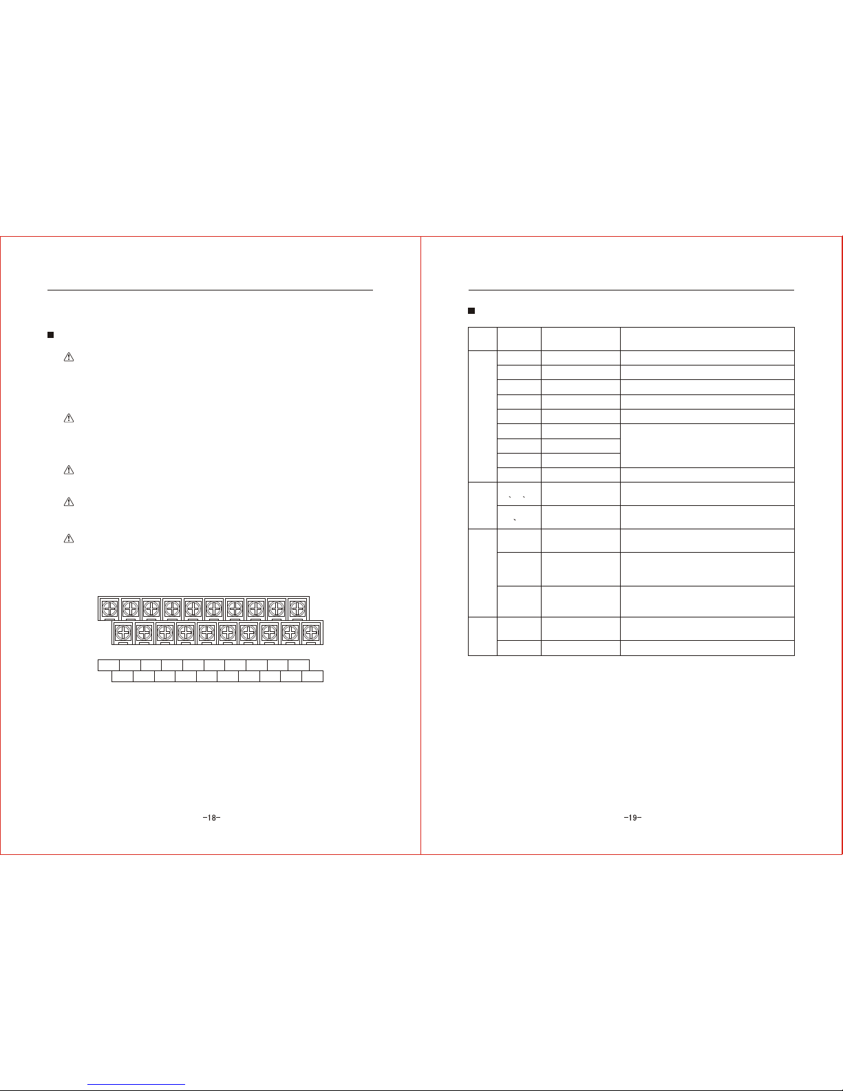
COM
STF
STR
EMS
RST
X1
X2
X3
X4
TA¡¢TB¡¢TC
Y1¡¢Y2
10V
VRC
+I
AFM
-----
+12V
TA TB TC X1 X2 X3 X4 EMS RST +12V
Y1 Y2 STF COM STR 10V VRC COM +I AFM
3.2.3 Connecting of the control circuit
Caution of the connecting circuit
Control circuit must be absorb creen wire and twisted
pair wire,and it must be connect to the key circuit .stav ing
circuit separatly.If the control circuit line must be cross
the the key circuit and other control line , it mustbe
vertical cross connecting.
Attention:
Attention:
Attention:
Attention:
Attention:
Control circuit is easily disturbed by the enviroment,
so the distancemust be short ( Generally no exceeding
30 meters).Analogue voltage .Ampere and potentiometer
input no exceeding20 meters.
In the condition of contact ,please use the reliable
contact point.
Be sure to install the surgue absorbing between the magnetic
coil which is occuring voltage surge ,it eliminates the voltage
surge that avoid the error action.
2
The wire for control circuit used to 0.75mm
Reference for the terminal of control circuit
Type Mark Title of terminal Reference of function
Input singnal
Public terminal
Positive rotata/stop
Reverse/stop
Accident exterior
Accident reset
Multi-speed 1
Multi-speed 2
Multi-speed 3
Crowl function
Positive rotate after connecting COM,break stop
Reverse rotate after connecting COM,break stop
Connecting COM,Inverter quick output
Connecting COM,accident reset
Connect or break X1.X2.X3with the COM,
can realizate switch run of eight section
Connecting COM,crowl run
Output signal
Accident relay output
Multi light output
TA-TB close when the accident protecting,TA-TB
breaking(Rated contact campacity AC250V 2A)
Look at "F098.F099"about the multi light input
chioce(light output DC24V 50MA)
Analogue input
Reactor input
Analogue signal input
Analogue signal input
Connect the potentionmeter and terminal of VRC.
COM,can Set frequency(potentionmeter 5-10k)
Connect analogue input voltage with the terminal
COM,can set frequency(analogue voltage signal
DC0-10V)
Connect analogue input voltage with the terminal
COM,can set frequency(analogue Ccurrent signal
4~20mA)
Connect voltmeterDC0~10v or Ampmeter0~1mA,
corresponding output 0~Max frequency
Output +12V power between terminal of COM
Power output
Analogue signal input
Analogue
output
Note: the list are the factory set
Article 3 Installation and ConnectionArticle 3 Installation and Connection
TATBTC
Y1 Y2

-4007T
-4015T
-4022T
-4037T
-4055T
-4075T
-4110T
-4150T
-4185T
-4220T
-4300T
-4370T
-4450T
-4550T
-4750T
-4930T
-41100
0.75
1.5
2.2
3.7
5.5
7.5
11
15
18.5
22
30
37
45
55
75
93
110
0.75
0.75
0.75
0.75
0.75
0.75
0.75
0.75
0.75
0.75
0.75
0.75
0.75
0.75
0.75
0.75
0.75
10A
10A
10A
16A
32A
32A
50A
63A
80A
100A
125A
160A
200A
200A
250A
315A
400A
10A
10A
16A
16A
25A
40A
40A
63A
63A
100A
160A
160A
160A
250A
250A
400A
400A
1.5
2.5
2.5
4
6
6
10
10
16
16
25
25
35
35
50
50
70
3.2.4Directory of complementelectric
Complement of circuit breaker.magnetic starter and the width of wire with the
Inverter
Article 3 Installation and Connection
-2015T/S
-2022T/S
1.5
2.2
0.75
0.75
16A
20A
16A
25A
Title
Max adapter
Motor(KW)
Key circuit
wire(mm2)
Control line
(mm2)
Circuit breaker
(A)
Contactor
(A)
-2007T/S 0.75 0.75 10A 10A2.5
2.5
4
-2037T/S
-2055T
-2075T
-2110T
-2150T
-2185T
-2220T
3.0
5.5
7.5
11
15
18.5
22
0.75
0.75
0.75
0.75
0.75
0.75
0.75
32A
50A
63A
100A
125A
160A
200A
40A
40A
63A
100A
160A
160A
160A
6
10
10
16
25
25
35
4.1
4.2
4.3
-21- -22-
4.1
Article4
Control panel and display
Control panel 22
4.1.1Figure of panel 22
4.1.2Reference of key on panel 23
Operation of control panel 24
4.2.1Data modify method 24
4.2.2Example of data modify 25
The content of dispay 27
This article are main introduce the figure of panel .key.
operation and the display,the user can understand the control
panel ,it is suitable for you operate it correctly.
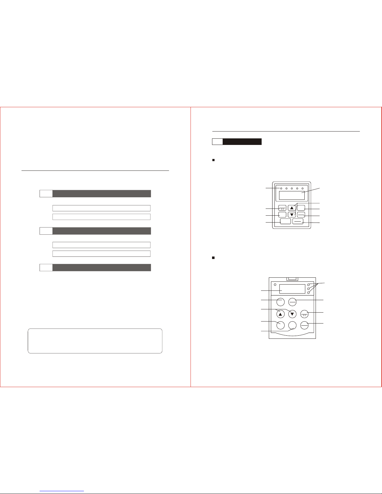
4.1.1 Figure of panel
Control panel(1)
Control panel(2)(with potentIometer)
RLN STOP JOG FWD REV
JOG
PRGM
REV
FUNG
DATA
RUN
STOP
RESET
JOG
PRGM
REV
FUNG
DATA
RUN
STOP
RESET
FWD
REV
JOG
STOP
LED display area
Display current status:run.stop.
crowl.positive.reverse
crowl/remove
reverse
run
LED desplay Area
Display freguency out put.
power.setted parameter
inerease/introduce
program
function/informa
stop/reset
LED display Area
Display out put frequency.electrie.
setted parametr
program
introduce/increase
run
reverse
Display Area
Displuy current status
run.stop.croue.
positive and reverse
function/information
crowt/remove
stop/reset
Article4 Control panel and display
Control panel
-23-
4.2
-24-
1
2
3
4
5
6
4.1.2 Illustration of key
Illustration of panel
Symbol Title Reference of function
Start reverse rotate
Stop/reset
Set
Function/display
Increase
Reduce
Crawl
Press it start run(If set F001 asthe exterior control,
it is expiry)
Press it start reverse run(If set F001 as the exterior
control or F004 is 1,it is expiry)
Press it stoprun(If set F001 as the exteriorcontrol,it
is expiry).After accidentwarning,press this can reset.
Press this enter into the setting situation,after you
completed modify,press this can recede from the
setting situation.
In theconditionof setting,press it as theconfirm code,
after completed thedata modify,pressit as the deposit
of the data.In the conditionof run,press thisas display,
such asoutput frequency.speed.output current andso on.
In the settingcondition,press this can increase code
of function .dataof parameter.In run or stand-by,press
this can increasethe frequency of run.
In the setting conditio n,press this can reduce code of
function .data ofparameter.In run or stand-by ,press
this can reducethe frequency of run.
In the condition of stand-by(F021=1),press this operate
crawl action.In the condition of setting,when you want
to modify the data,press this can choose the position
of modify data.
Illustration of indicator
Title of indicator
Illustration
Stop
Positive
Reverse
Crawl
After the Inverterconnect the powerand it is
not start theindicator is lighting.
After the Inverterconnect the power and press
the positive key,the indicator is lighting.
After the Inverter connect the power and
press the reversekey,the indicator is lighting.
After the Inverterconnect the power and press
the crawl key,the indicator is lighting.
Control panel operation
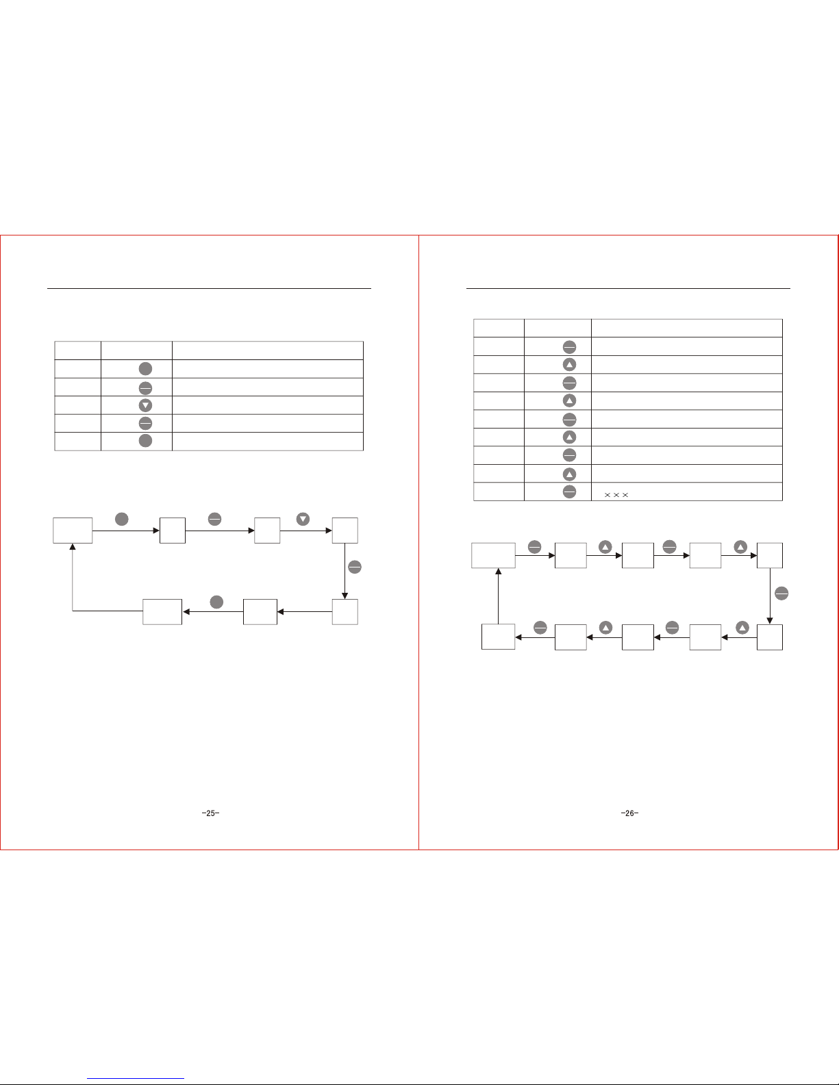
4.2.1 Method of the data modify
If you need to modify the data,first enter into the function code which
will be modified,then reset the data,the process as following:
Subsequence
Operation Illustration
Display F000,enter intothe function setting.
Adjust to the function data which will be modified.
Display = ,enter the data setting situation
Reset the parameter value according
your requirement.
Display the END quickly,deposit the data,then
display the function code F
Recede the setting condition,turn back to the
stand by or run condition.
Display function
code F
Display modify
code
Display
parameter
Display the
modified
parameter
Deposit,
display END
code F
display
function
Recede
from setting
condition
Article4 Control panel and displayArticle4 Control panel and display
RUN
REV
STOP
RESET
PRGM
FUNC
DATA
JOG
<<
RUN
setpress
press JOG
<<
FUNC
DATA
press
press JOG
<<
FUNC
DATA
press
setpress
set JOG
<<
FUNC
DATA
JOG
<<
FUNC
DATA
set
1
2
3
4
5
1
2
3
4
5
6
7
8
9
4.2.1 Example of the data modify
No.1Example :Change output frequency 50HZ to 25HZ
Subsequence
Operation Illustration
Display F000,enter intothe function setting.
Display=500,enter into parametermodified.
Continue press thisuntill display=25.0
Display the END quickly,deposit the data,then
display the function code F000
Recede the setting condition,turn back to the
stand by,display H25.0
Display H50.0
stand by
Display
F000
Display
=50.0
Display
=25.0
Display
END
display
F000
Completed
setting
frequency
Recede from
setting condition
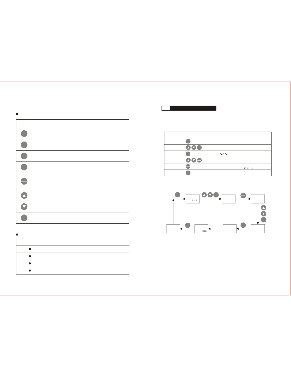
No.2Example :Recovery the factory data(data initialize)
Subsequence
Operation Illustration
Display F000,enter intothe function setting.
Press four times,displayF004.
Press one time,0 in thebetween is flashing
Press one time,displayF014.
Press one time,theforward 0 isflashing
Press one time,displayF114.
Display=0,enter into settingstatus
Press one time,display=1
All display data flashing one time,then display
H ,completed recover factory data
Stand by
display H50.0 Display
F000
Display
F004
Display
F004 Display
F014
Display
F014
display
F114
display
=0
display
=1
Recover
factory
data
Recede from
setting condition
Article4 Control panel and displayArticle4 Control panel and display
set
FUNC
DATA
FUNC
DATA
set
press
press
press
press
press
set FUNC
DATA
FUNC
DATA
set
FUNC
DATA
press
press
JOG
<<
press JOG
<<
press
press JOG
<<
press
FUNC
DATA
press
press
FUNC
DATA
press
FUNC
DATA
JOG
<<
FUNC
DATA
FUNC
DATA

4.3
5.1
5.2
H
P
C
U
D
N
Content of display on the control panel
Inverter in the stand by status,when you press "Display"key,display
cycle as follows.
Stand by or
run status
H50.0 or P50.0
display
d XXX
display
C XXX
display
U XXX
display
n XXX
Display
b XXX
Display
L XXX
Display
o XXX
Illustration
Code
Inverter in the status of stand by,display frequency of it
Inverter in the status of run,display frequency of it
Display the outputcurrent of therun
Display the outputvoltage of therun
Display theAC voltage ofbus bar wire
Display the presentspeed of theInverter
Display the feedbackdata when PIDrun
Display the datasetted when PIDrun
Display the dataof the counter
Display the temperatureof the module
Run-in test
Article 5
Run-in test 29
5.1.1Caution of the safty 29
5.1.2Checking before the Run-in test 29
5.1.3Run-in test 29
Operation of run 30
5.2.1Caution of the safty run 30
5.2.2Operation of run 30
This article are introducing the caution of operation,it is
including the checking item before run .the process of Run-in
test and the several operation method.
Article4 Control panel and display
J
b
L
o

5.1
1
3
4
5
6
7
5.2
2
Run-in test
5.1.1 Caution of the safty before Run-in test
Install well the shell when it run,do not dismount the shell
when it runs,avoid the electric shock.
Before run-in test ,it must be unload run,avoid the destroy
by the error action.
Dangerous:
Attention:
5.1.2Checking before run-in test
Be sure tocheck and confirmbefore run-in test:
5.1.3 Run-in test
After checking and confirm by the clause 5.1.2,you can run-in test .You
would better choose key control the the run manner.Run-in test
in process as follows:
Subsequence
Operation Illustration
Close the switch,
Inverter run
In status of electric ,Inverter is in status,
display H ,interior fan start work
Press key untill
frequency display P5.0
If itdisplay H5.0 ,ignore this process
Press start key
Motor start ,Inverter display inrease from
P0.0 to 5.0
Check :
1.Whether motor run well;
2.Whether noise and
abnormality;
3.whether the correct
direction
If abnormality happened,please stop the run
and cut off the electric ,then check the accident,
restart it after repair it.If you found the motor
run reverse against your requirement,change
each two of connection U.V.Wis ok.If everything
is ok,operate the next step.
Press Up key
continously untill frequency
display is P50.0
Press Up key
continously untill frequency
display is P0.0
Press stop key
Motor speed up ,frequency display increase from
P5.0 to P50.0;if everything is ok,operate the next
step.
Motor speed down ,frequency display reduce from
P50.0 to P0.0;if everything is ok,operate the next
step.
Inverter stop to output,motor stop rotate,run-in test
finish.Gernerally,please repeat servral times. from the
first step to the seventh step
Run operate
5.2.1 Cautions inruning status
Install well the shell when it run,do not dismount the shell
when it runs,avoid the electric shock.
Do not operate the Inverter by the damp hand,avoid
electric shock.
When the Inverter set the function of restart after power
off,please put a warning sign "Do not approach" beside it.
Otherwise it will prevent the human after the start abruptly.
The Inverter has install the radiator and exterior brake
resistance,so please do not touch it.It is heat.
If the Inverter set in high speed status,please confirm
it is able before.
Attention:Do not change the setted parameter if you have
not special requirment, because it is been fixed by the
factory.Avoid the distroy by the change.
Dangerous:
Dangerous:
Dangerous:
Dangerous:
Attention:
Attention:
5.2.2Run operation
In the status of run,setting frequency can adjust directly on the line.
All function of Inverter depend on the the parameter setted,this style of
Inverter is make up by function code 001~116,detail as directory 6.1.The
parameter displayed is the factory parameter,user can adjust it by the
private requirement.Because the parameter are relevant
parameter,when user modify some parameter,it better modify the related
parameter.If user modify error or disorder the parameter,please initialize
parameter according examples 2 by clause 4.2.2.(Initialize factory
parameter)
Article 5 Run-in testArticle 5 Run-in test
STOP
RESET
RUN
RUN
STOP
RESET

-31-
6.1
6.2
6.1
-32-
F000
F001
F002
F003
5.0Hz
0
0
0
50.0Hz
220V
380V
50.0 Hz
25.0 Hz
50%
0.0 Hz
1%
F011
F012
F013
0 100%
0 100%
50.0 110%
100%
1%
100%
F004
F005
F006
F007
F008
F009
F010
200V 160.0V 240.0V
400V 320.0V 480.0V
(F007) 400.0Hz
0.0 10.0 Hz
Article6
Function parameter illustration
Function parameter directory 32
Detail illustrationof functionparameter 39
This article express the function parameterof Inverter.
When user set the function parameter,please read it carefully,
in that case,user can avoidthe error setand the accident.
Directory of function parameter
Function of control
Function
code Title of function Range of set Factory
parameter Note
Run frequency 0.0~max frequency(F004)
Choice of
runing control
0: panel control (positive start,reverse
start,stop)
1: ExteriorTerminal control (positive
start/stop, reverse/stop)
2: ExteriorTerminal control (positive
start/stop, reverse/positive)
3: ExteriorTerminal control (positive
start, reverse start,stop)
Choice of
frequency setting
Choice of stop
0: panel up/down
1: Panel reactor
2: Exterior reactor or exterior
voltage 0~10VDC
3: Exterior input current4~20mA
4: Exterior up or down
0: reduce stop
1: free stop
2: immediate AC brake
3: Exterior free stop
V/F curve setting
Function
code Title function Range of setting Factory
parameter Note
Highest frequency Lowest frequency~400.0HZ
High voltage
Rated motor frequency
Medium frequency
Lowest frequency(F009)~
Highest frequency(F004)
Medium voltage
Lowest frequency
Lowest voltage
Lowest voltage(F010)~99% rated voltage
0~10%rated voltage
Basic function
Function
code Title of function Range of setting
Factory data
Note
Highest frequency
corresponding input
Lowest frequency
corresponding input
Rated current of
Article6 Function parameter illustration

-33- -34-
F014
F015
F016
F017
F018
F019
0.0 10.0Hz
0.0 60.0S
50.0 Hz
1.0 Hz
1.0 Hz
0.5S
F025
F026
F027
F028
F029
F030
F031
F032
F033
F034
F035
F036
F037
F020 0
F022
F023
F024
F021
F038
F039
F040
F041
F042
F043
F044
F045
1
0
0
0
0
0
0
0
0
0
0
0
0
0
0
0
0
F047
F048
F049
F050
F051
F052
F053
F054
F055
F056
F057
F058
F059
F060
F061
F062
F063
F046 0
Basic function(continous upstair)
Function
code Title function Range of setting
Factory
parameter
Note
Toplimitfrequency
Lowlimit frequency
start frequency
Start delay time
Speed time
Reduce time
Increase/reduce
curve
Lowlimit frequencyF015~400HZ
0.0~ toplimit frequency(F014)
0: straight line
1: S curve
0.1~999.9S
0.1~999.9S
10.0S
10.0S
Crawl function
Function
code Title function Range of setting
Factory
parameter
Note
Choice crawl
crowl frequency
Time speed up
Time speed down
0:the function expiry
1:the function validity
Lowest frequency (F009)
0.1~999.9S
0.1~999.9S
0
5.0Hz
5.0s
5.0s
Multi speed run
Function
code Title function Range of setting
Factory
parameter
Note
Second frequency
Second speed up time
Second speed down time
Third frequency
Third speed up time
Third speed down time
Fourth frequency
Fourth speed up time
Fourth speed down time
Fifth frequency
Fifth speed up time
Fifth speed down time
Sixth frequency
Highest frequency(F004)
0.1~999.9S
0.1~999.9S
Highest frequency(F004)
0.1~999.9S
0.1~999.9S
Highest frequency(F004)
0.1~999.9S
0.1~999.9S
Highest frequency(F004)
0.1~999.9S
0.1~999.9S
Highest frequency(F004)
5.0Hz
10.0S
10.0S
10.0Hz
10.0S
10.0S
20.0Hz
10.0S
10.0S
30.0HZ
10.0S
10.0S
40.0HZ
Multi speed run
Function
code Title function Range of setting
Factory
parameter
Note
0.1~999.9S
0.1~999.9S
Highest frequency(F004)
0.1~999.9S
0.1~999.9S
Highest frequency(F004)
0.1~999.9S
0.1~999.9S
sixth speed downtime
Seven frequency
Seven speed uptime
Seven speed downtime
Eighth frequency
Eighth speed uptime
Eighth speed downtime
Sixth speed uptime 10.0S
10.0S
50.0HZ
10.0S
10.0S
50.0HZ
10.0S
10.0S
Program run
Function
code Title function Range of setting
Factory
parameter
Note
Mode of
program run
0: expiry
1: Stop after single cycle run
2: Run cycle
3: Maintain the last frequency
after single cycle run
1~100
0~999.9S
0:positive 1:reverse
0~999.9S
0:positive 1:reverse
0~999.9S
0:positive 1:reverse
0~999.9S
0:positive 1:reverse
0~999.9S
0:positive 1:reverse
0~999.9S
0:positive 1:reverse
0~999.9S
0:positive 1:reverse
0~999.9S
0:positive 1:reverse
Program run coefficient
Program run at1 temporal
Program run at1 direction
Program run at2 temporal
Program run at2 direction
Program run at3 temporal
Program run at3 direction
Program run at4 temporal
Program run at4 direction
Program run at5 temporal
Program run at5 direction
Program run at6 temporal
Program run at6 direction
Program run at7 temporal
Program run at7 direction
Program run at8 temporal
Program run at8 direction
Article6 Function parameter illustrationArticle6 Function parameter illustration

1000
100%
0
0
1.00
1.0
1.0
100%
F067
F068
F069
F070
F071
F072
F073
F074
0 9999
0 100%
0 9999
0 100%
0.00 99.99
0.0 99.9S
0.0 99.9S
0 200%
-35- -36-
F075
F076
F077
F078
F079
0
1
0 9999
F064
F065
F066
0
0
1
F080 0 9999 1
F081 0
F082
F083
F084
F085
F086
F087
F088
F089
F090
F091
F092
0 30%
0.0 5.0Hz
1 12K Hz
0.0 400.0Hz
0.0 200%
50 150%
0.01 99.99
1
4%
0.0 Hz
5
0
0.0 Hz
100%
0
100%
0
30.00
PID function
Function
code Title function Range of setting
Factory
parameter
Note
PID mode choice
PID aim parameter
PID original parameter
PID max aimparameter
Max parameter feedback
PID minimum parameter
Min parameter feedback
Proportion gain
Integral time
Differential time
Feedback coefficient
0:PID function expiry
1: PID validityexpiry
0: Panel key
1: Panel reactor
2: Exterior reactor or anologue
voltage 0~10v
3: Exterior anologue
current 4~20mA
4: Exterior lift/fall lift
0: Exterior voltage
1: Exterior current
Ac brake function
Function
code Title function Range of setting
Factory
parameter
Note
AC brake time
AC brake frequencystarting
AC brake torque
0.0~25.0S
0.0~25.0HZ
0~30%
0.3 s
3.0HZ
4%
Counter funtion
Function
code Title function Range of setting
Factory
parameter
Note
Counter mode
Counter parameter
0:Expiry
1:Mode of upcounter
2: Mode ofdown counter
Function
code Title function Range of setting
Factory
parameter
Note
Counter coefficient
Counter dealing
0:Stop count ,close output
1: Stop count ,continous output
2: Restart count,close output
3: Restart count,continous output
Special function
Multi-speed run (Continous)
Function
code Title function Range of setting
Factory
parameter
Note
AVR founction
Torquelift
Slip compensation
Carrier wave frequency
Restart after
Instant stop
Frequency arrive setting
Analogue input gain
Analogue
output choice
Analogue output gain
Starting
display
choice
Speed coefficient
0:Expiry
1:validity
0:Expiry
1: Quick run after electric recover
2: Quick start after electric recover
0:Analogue cymometer
1: Analogue Ammeter
2: Analogue Volmeter
0:Output frequency
1: Output current
2: Output voltage
3:AC bus barvoltage
4:Motor speed
5:PID parameter feedback
6:PID aim parameter
7:Parameter of count
8:Temperatureof module
Article6 Function parameter illustrationArticle6 Function parameter illustration
This manual suits for next models
1
Table of contents
Other Chziri Inverter manuals


Popular Inverter manuals by other brands

WEG
WEG CFW-11 Series user manual

Champion Power Equipment
Champion Power Equipment 100246 Owner's manual & operating instructions

INSBUD
INSBUD IB-INV-CSI manual

MULTIQUIP
MULTIQUIP WHISPERWATT DCA150USJ3CAN Operation and parts manual

Tronic
Tronic TSW 150 A1 operating instructions

Mitsubishi Electric
Mitsubishi Electric FR-F862 instruction manual


