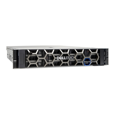
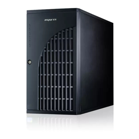
Fibrenetix SVS Series User manual

Quick Installation guide for the
SVS Server series (RS9)
Version 1.0 (January 2017)

IMPORTANT STATEMENT
Please read and follow the installation instructions carefully before connect the system to its power
source.
Unpacking
When you receive the system, visually inspect the exterior of the packaging for any signs of damage. If any
damage is found, you should inform your distributor. Once the packaging is opened, the contents should be
checked. If any items are missing or damaged you should contact your distributor immediately.
Contents
Remove all items from the box. Put all items from box on a flat surface. Make sure that all items are taken
from box.
DO NOT INSERT DRIVES INTO THE SYSTEM BEFORE IT IS MOUNTED IN THE RACK!
Hardware installation
Installation in rack
When all items are taken out of the box –prepare for installation in a rack.
To install the system in a rack with the kits, please follow the procedure
1. Prepare the rails and the screws
2. Assemble the rail kits
by sliding them together

3. At the FRONT put the nuts on the appropriate place. Then use the screws to install the mounting
brackets
4. Similarly, at the REAR, put the nuts on the appropriate place and the use the screws to install the
mounting brackets.
5. Slide the system onto the rails.
CAUTION !!!!
The system is heavy. To avoid personal injury and damage to the system,
it should be installed by two persons.

Installing disk drives in system
Warning: Disconnect the power supply inlets before opening the storage enclosure for maintenance.
Caution: Do not place or drop objects onto the enclosure and do not force any foreign objects into it.
When the system is mounted and secured in a rack then install the disk drives.
To install a Disk Drive caddy in the storage enclosure, follow the procedure below:
Orient the caddy so that the LED indicator is at the left hand side.
With the locking lever fully open, gently slide the caddy into the desired slot on the front of the
enclosure.
When the caddy is in all the way, slowly close the locking lever until it clicks into place.

Connecting RAID Controller’s Ethernet and RS232 Port
Connect the Ethernet port of the RAID controller using an Ethernet cable to a LAN port or LAN switch.
SAS RAID controller expander port supports daisy chain expansion to a JBOD.
The SAS RAID controller can support daisy chain of up to 8 enclosures. The maximum drive no. is 256
devices through 8 enclosures. The following figure shows how to connect the external Mini SAS cable from
the iSCSI RAID controller to additional JBODS.
Daisy Chain
If expanding to a 16 Bay JBOD connect the
SAS expansion cable from the top RAID
Controller to the top JBOD Module
If expanding to a 60 Bay JBOD connect the
SAS expansion cable from the top RAID
SAS Cable

Attaching the SAS Channel Cables to a JBOD enclosure
The SAS JBOD cable is supplied with the JBOD expansion enclosure and connects from a SAS expansion
port of the E8 - the (EXT0) to a port on the JBOD. The E8 connector type is mini-SAS.
SVS Server Raid-controller
Connect the Raid controller to Host (0). If expanding further connect Host (3) to Host (0) on the next JBOD
E8-60 Bay JBOD
On the JBOD connect the SAS cable to Host 0
If expanding to further JBOD Systems connect the SAS cable to SAS Host3
60 Bay JBOD

Rear of 60 Bay JBOD

E8-12-BAY-JBOD
E8-16-BAY JBOD
E8-12/E8-16 BAY JBOD-controller
On the JBOD connect the SAS cable to SAS CH1 (IN)
If expanding to further JBOD Systems connect the SAS cable to SAS CH0
Mini-to-mini-SAS cable

Log on to the controller
Main menu of the RAID controller:
Creating a RAID set
Go to RAID functions in the left menu:
Select create RAID set
Next step is to create a Volume of the RAID Set.
Select all drives by clicking
each one. There is no option
‘SELECT ALL’.
Click the ‘Confirm The
Operation’ and click Submit
when done.
You have now created a RAID
SET
Enter username: admin
enter password: 0000 (4 zeros)

Creating a Volume set
To create a Volume based upon the newly created RAIDSET –go to the Volume menu on the left.
To create a Volume set click on
the RAID set available in the
window on the right. If more
RAID sets were created, they
would appear in this window.
Press Submit to continue the
operation

Configuring the Volume set
The volume set must be configured as follows as FibrenetiX standard:
Volume Name: FibreX-VOL-#000
The Volume name must be ‘FibreX’-VOL-#000
Volume Raid level: RAID 5
If nothing else is requested the RAID level must
be RAID5
Greater that 2 TB Volume Support: 64Bit LBA
If this is not set you will not be able to use all the
disk spoace.
Confirm the Operation and Submit

Additional settings
Go to the System Controls menu on the left and select System configuration
Configure Hot plugged disk for rebuilding
Go to Advanced configuration and configure the buffer threshold.
Buffer Threshold Setting.
Hot plugged disks must be
configured for rebuilding
ALWAYS. This options will
ensure that the RAID set will
rebuild automatically when a
new disk is inserted as
replacement for a faulty disk
Confirm the Operation and
Submit
Buffer Threshold Setting must be set to 5%
Confirm the Operation and Submit

Progress of Volume initialization
To view the progress of the initialization of the Volume set –go to the information menu and select RAID
set Hierachy
The progression of the
buildup of the volume will be
shown in % in this window
When done the Volume state
will be ‘Good’

Create Volume in Windows
When the controller has finished initializing the volume, it is possible to add the volume in Windows .
Go to Diskmanagement and follow these steps


Superdoctor
1. Logon to SuperMicroDoctor utility,
username: admin
password: admin
In an 8 bay server fans 4,5,6, A & B should not be selected. There should be no voltages selected for CPU2.
V DIMM EFand GH should not be selected. The temperature for CPU2 should not be selected.
In a 16 bay server fans 4, A & B should not be selected. There should be no voltages selected for CPU2. V
DIMM EF and GH should not be selected. The temperature for CPU2 should not be selected.
In a 2 CPU configuration the Voltage for CPU2, memory slots V DIMM EF and GH and temperature for CPU2
should all be selected.
2. Test fan failure is detected. Remove one fan from the fan tray. Fan speed should increase on the
remaining fans. An alarm should sound and a red indicator on the front of the server should
indicate fan failure. Reinsert the fan to it’s position. The fan should spin up and all fans should
return to normal operating speed and the alarm should be silenced. The LED on the front should be
turned off.
3. (all fans working properly)

(one fan removed af has trickered an alarm)
4. Remove one power cord from either of the PSU. This will sound the beeper alarm.
Remember to check LED at the front. Red light at PSU should turn on and turn off when PSU is
reinserted. Do this for both PSUs.
5. Intrusion Detection must NOT be selected in Configuration.
6. Save and Exit
One fan removed and alarm is
trckered. Remember to check LED
at the front. Red light at FAN
should turn on and turn off when
fan is reinserted
Intrusion detection must be
disabled
Table of contents
