FibroLAN Falcon Instruction sheet

Falcon
Product Technical Note
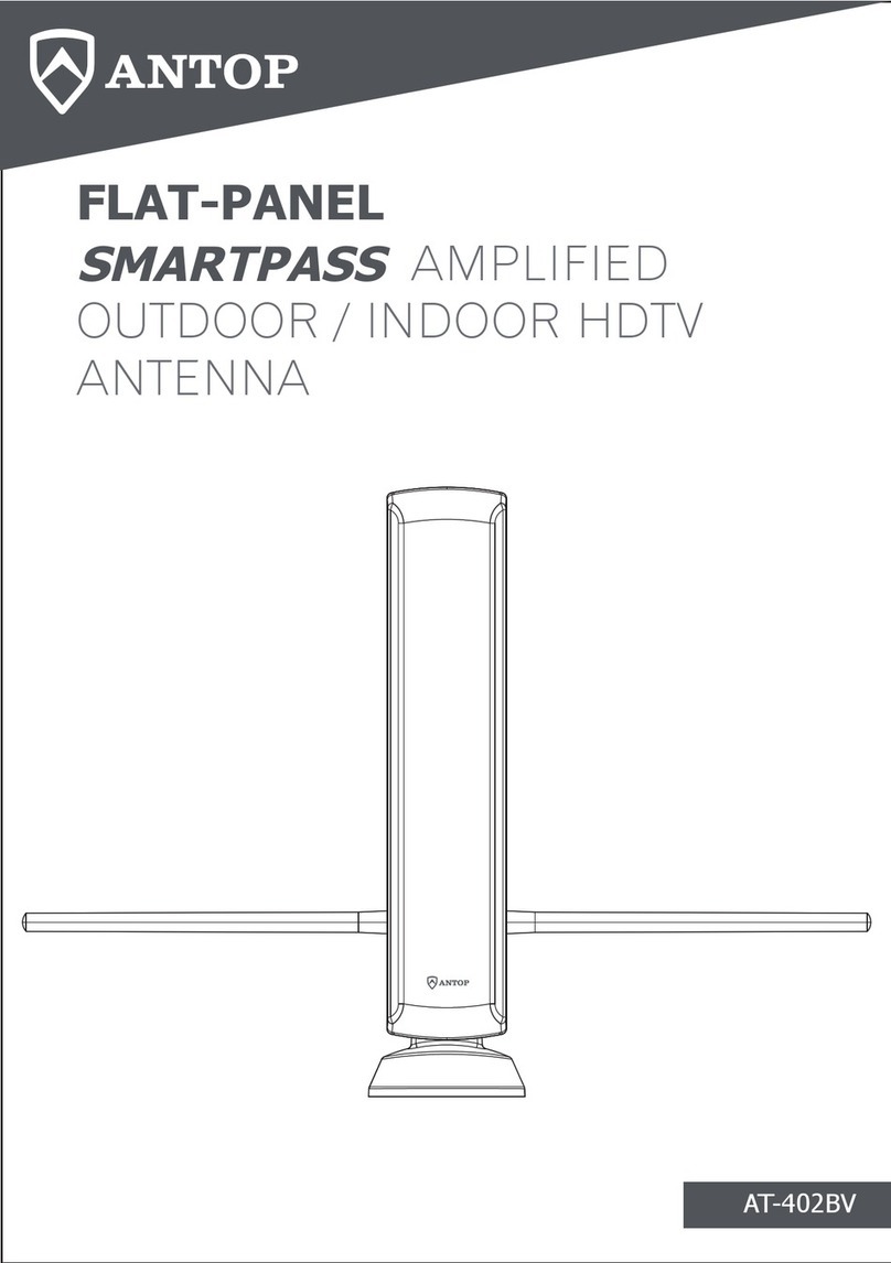
GPS/GNSS Antenna and Receiver
Installation Guidelines
Document version: 1.8
Proprietary Information. This document contains information, which is proprietary to Fibrolan
Ltd. No part of its contents may be used, copied, disclosed or conveyed to a third party in any
manner whatsoever without prior written permission from Fibrolan Ltd.
www.fibrolan.com

G P S / G N S S A n t e n n a I n s t a l l a t i o n G u i d e l i n e s
2 | P a g e
GNSS Antenna and Receiver
Installation Guidelines
Falcon /G models (µFalcon-MX/G, Falcon-MX/G, µFalcon-ST8/G, Falcon-MTS and Falcon-RX/G)
include an integrated Global Navigation Satellite System (GNSS) receiver. It is a multi-constellation
(GPS, GLONASS, Galileo, Beidou) receiver designed to provide high precision and stable
synchronization in Telecom and Enterprise environments.
A GNSS receiver obtains timing source signals transmitted by the satellites orbiting the Earth, and
processes them, generating synchronization schemes. To ensure the optimal performance, as
many as possible satellite signals should be delivered to its GNSS input. To this end, key aspects
must be thoroughly considered:
1. Location and antenna installation recommendations
2. Antenna and transmission system selection
Notice:
1. These guidelines do not release the user from full and absolute
compliance with Federal, state, city or local laws, rules, standards or
regulations that may be applicable, including (but not limited to) matters
of safety, licensing, building etc. Such compliance is the user's absolute
and exclusive responsibility. In case of conflict between such and these
guidelines, consult Fibrolan.
2. Good operation of the GNSS relies on proper environmental conditions
and adequate and professional installation execution. Fibrolan is not
responsible for the success of the actual installation.

G P S / G N S S A n t e n n a I n s t a l l a t i o n G u i d e l i n e s
3 | P a g e
1Location and antenna installation recommendations
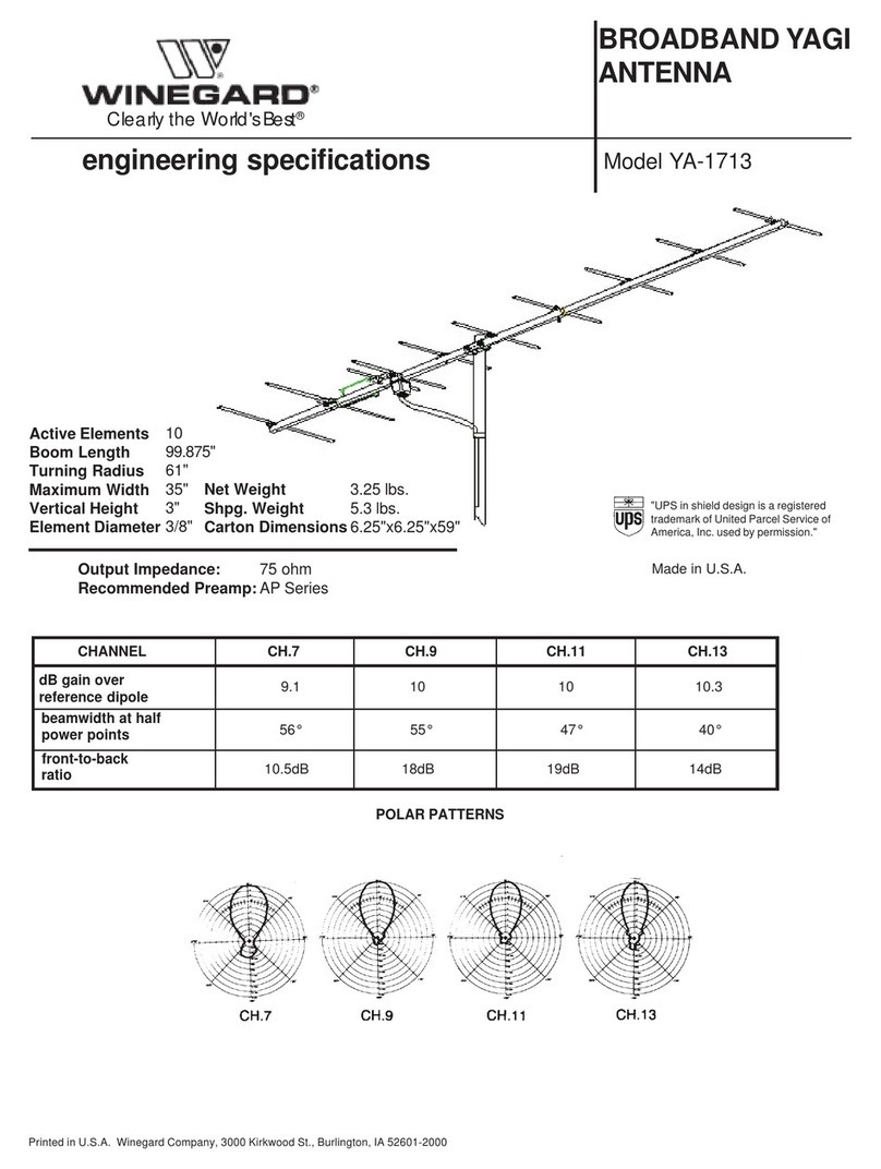
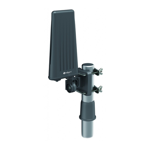
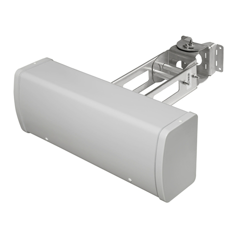
The GNSS antenna should be installed at a location thatwill enable optimal performance and avoid
interference from external sources. The following installation guidelines will assure the GNSS
antenna provides such optimum performance.
1.1 General considerations
•GNSS antennas are typically installed on roof-top/tower or on the side building. Whenever
possible, prefer a roof-top or tower installation.
•Use professional and adequate accessories for installation. Such may be ordered (optionally)
from Fibrolan.
•Position the GNSS antenna at a minimum of 1.5m / 5 ft distance from any metallic object and
a minimum of 1m / 3 ft distance from any other GNSS antenna
•Do not deploy antenna in the vicinity of other transmitting antennas and radars.
•While antenna and cables withstand rain, do not deploy where these may be immersed in
water.
•Do not deploy in a spot that may be covered with snow, foliage, or massive pollution. As a
good practice, perform a visual check of the antenna and cable once every 3 months or if
reception problem, and clean up when needed.
•Install at a location with maximal uninterrupted exposure of the sky dome. This will maximize
number of satellites tracked consequently improving quality of the received signal.
•Minimize the outside cable segment (i.e. enter the building as close as possible to the
antenna)
1.1.1 Roof-top (tower) installation considerations
•Install the GNSS antenna at the highest position on the roof to however at least 1 m (3ft)
below a lightening protector rod to minimize the hazard of direct lightning strikes
•Install the antenna at a point that ensures a clear and unobstructed view of the sky dome,
360° horizontally and about 15° above the horizon
•If installed on a tower, distance the antenna at least 1m (3ft) from the tower itself using a
horizontal beam, observe the rules regarding other emitting antennas
Figure-1: Antenna visibility requirements

G P S / G N S S A n t e n n a I n s t a l l a t i o n G u i d e l i n e s
4 | P a g e
1.1.2 Wall side installation considerations
•Prefer building side facing the equator (if available- corner position). The minimal 180°sky
view rule must be observed at a horizontal distance of at least 500 m (1500 ft).
•Use brackets/ spacers to keep a gap of not less than 50cm from the wall surface and make
sure there is no balcony (or another object) that may obstruct upward view.
1.2 Installation examples
In the figure below there are three examples for antenna installation locations.
Case 1: most suitable option, clear neighborhood assumed.
Case 2: acceptable option with reduced visibility, clear neighborhood assumed.
Case 3: unsuitable option with very poor exposure to the sky dome, resulting in a very small
number (perhaps none at times) of satellites to track.
Figure-2: Examples of antenna installation location
In cases where good sky dome exposure cannot be secured, consult Fibrolan for alternatives based
of extended holdover and other unique mechanisms available on certain models. Such, will
maintain synchronization for a given period even at the absence of adequate satellite signals. As,
satellites position in the sky constantly shift; it is possible that part of the day the GNSS receiver
will not track enough satellites (even none for short periods).

G P S / G N S S A n t e n n a I n s t a l l a t i o n G u i d e l i n e s
5 | P a g e
2Antenna and transmission system selection
It is recommended to obtain the antenna, cable and other accessories from Fibrolan along with
the timing device. This will ensure full support and higher performance of the solution.
In case the antenna or accessories are procured from a different source, the following guidelines
are advised. In such case, Fibrolan may offer consulting regarding the timing device, however,
cannot assume any responsibility for its operation nor the performance of the entire system.
2.1 Antenna Selection
It is advised to select the antenna from a reputable vendor and with the following technical
specifications:
•5 VDC active antenna (except the µFalcon-ST/G model, which requires a 3.3 VDC antenna)
•Minimum gain of 25dB. For long cable runs (>50m) use higher gain antennas (e.g. 50dB)
•50Ωor 75Ω(ohm) impedance.
•Antenna should support at least the GPS system. However, GNSS multi constellation is highly
recommended.
•If available (and budget allowing) prefer to use of multi-band antennas
•Verify the availability of suitable mounting accessories (rod, brackets, etc.).
2.2 Transmission system
The typical transmission system delivers the GNSS antenna signal to the timing device input
interface. It comprises of several elements:
•Cables
•Lightening arrestor
•In-line amplifier (optional)
•Splitters (optional)
•Adapters (optional)
•Other Accessories
The following drawings describe three of the typical installations. Figure-3 describes a standard
point to point installation, where the minimum gain at the receiver input should not fall below
15dB.
Figure-3: Point to point installation
In cases where the transmission system length is greater an in-line amplifier may be introduced in
front of the receiver, as shown in Figure-4. Alternatively consider using a higher gain antenna

G P S / G N S S A n t e n n a I n s t a l l a t i o n G u i d e l i n e s
6 | P a g e
instead. As a rule of thumb, consider that each 10 meters of cable reflects in up to 3dB loss, also
arrestor and impedance mismatches may add ap to 2dB in total
Figure-4: Point to point installation with amplification
If more than a single receiver is connected to the antenna a powered/amplified splitter is installed.
Figure-5: Multiple receiver installation with splitter
2.2.1 Cables
Fibrolan recommends using 50Ωor 75Ωcoax cable for connecting the GNSS antenna to the Falcon
GNSS receiver port.
•the GNSS receiver as well as other elements are typically 50 Ωtherefore when using a 75 Ω
cable, an extra loss of 1-2 dB in total should be accounted for.
•Fibrolan provides pre-terminated cables of various lengths. These are RG6/ quad shield type
featuring a maximal loss of 0.27dB/m (at the relevant frequency). It is of 75 Ωimpedance
however the mismatch losses are outbalanced by the inherent insertion loss.
•If cables are sourced elsewhere, they should be of similar or better characteristics
(e.g. RG8 or LMR400).
•An outdoor segment from the antenna to the indoor entry point should be accounted for due
to the need to insert a lightening arrestor (see below)
•In case an in-line amplifier/splitter is required (see below), additional cable segments are
needed.
2.2.2 Lightning arrestor
A lightning arrestor is a mandatory and critical component of the Transmission System. The
arrestor aims at two crucial points in the event of a lighting (direct or indirect) strike:
•Prevent risk of injury.
•Minimize damage to interconnected equipment and infrastructure.

G P S / G N S S A n t e n n a I n s t a l l a t i o n G u i d e l i n e s
7 | P a g e
The lightning arrestor interconnects the indoor and outdoor segmentsof the cable, at indoor entry
point. It must be installed by a certified electrician. The lightning arrestor must be properly
grounded to allow correct discharge of any excess current created on the antenna and cable.
The Lightning Arrestor provided by Fibrolan is includes 2 female TNC connectors. If the arrestor is
sourced elsewhere, it should only be from a certified vendor and ensure low insertion loss
(typically 0.1dB).
2.2.3 In-Line Amplifier
In case the total gain at the Falcon GNSS input drops below 15dB an in-line amplifier is required.
For example, Fibrolan’s GNSS antenna model GPANT-4's gain is 28dB, which can be translated to
a maximum of 13dB attenuation for the entire transmission system (indoor+ outdoor) without
amplification. The ideal position of the In-Line Amplifier would be near the receiver. The gain at
the edge of amplified segment (from the amplifier) connected to the Falcon GNSS input should
not exceed 30dB (to avoid saturation).
While selecting an In-Line (unless sourced from Fibrolan) assure it provides 5V towards to antenna
The introduction of in-line amplifiers further complicates the transmission system, therefore –
unless user has extensive knowledge and expertise in this field –it is highly recommended to
consult Fibrolan or a professional installer. Up to 30dB amplifiers are available from Fibrolan.
Unless the antenna is already purchased or installed, it is recommended to avoid using the
amplifier and rather select a higher gain antenna instead –in most of the cases this may prove
better both economically and operationally.
2.2.4 Splitter
If the Antenna is connected to more than a single device a splitter is required. The Antenna must
be connected to the splitter’s input interface. The Falcon's GNSS receiver should be connected to
the DC Through output port when not using external power. If an externally powered splitter is
installed all ports should be DC Blocked and the antenna is fed by the external source. As Passive
splitters introduce additional attenuation, they are not recommended, and it is advised to consult
the manufacture datasheet before installation. Active splitters are the preferred type, as they also
function as an amplifier. Splitters are available in various output interface configuration.
Figure-6: Splitter connectivity options
2.2.5 Adapter
Some Falcon models (e.g. µFibrolan-MX/G) models, equipped with a GNSS receiver, use an SMA
connector (female) for antenna input. Therefore, a TNC (Female) -SMA (Male) adapter may be
required (available from Fibrolan or may be sourced elsewhere).
Falcon models equipped with a TNC connector do not require such adapter.

G P S / G N S S A n t e n n a I n s t a l l a t i o n G u i d e l i n e s
8 | P a g e
2.2.6 Other Accessories
Installation kits (e.g. mounting rod, clamps, base plate) are available from Fibrolan, user may
source elsewhere following a detailed survey of the installation environment
3Power and grounding installation
Falcon models can be installed with two load sharing, hot swappable, redundant AC or DC power
supplies. µFalcon models are equipped with dual DC feed power supply.
3.1 AC Power Supply
AC power supply of the Falcon models are connected using a standard power cord with an
IEC 60320 C13 connector. Some µFalcon models requires an FPA40 AC/DC power adaptor.
3.2 DC Power Supply wiring
DC power supply wiring details are described in the drawings and table shown below. Further
installation details are available at this Link.
µFalcon models
Falcon models
Figure-7: DC power supply and grounding
Power Source Type
Positive (L+, red)
Negative (L-, black)
-48 VDC
0V
-48V
24 VDC
20÷60V
0V
3.3 Grounding
Special care must be exercised. Assuming a properly installed lightning arrestor that is grounded
to the primary building grounding grid, the shield or frame ground attached to the µFalcon and/or
Falcon devices must have the same ground potential to help avoid electrical issues –surges, etc.
System grounding must be done correctly and in accordance with electrical, bonding & grounding
practices and safety codes that the installation site is governed by.

G P S / G N S S A n t e n n a I n s t a l l a t i o n G u i d e l i n e s
9 | P a g e
We’ve got Timing for you!
Intl. Headquarters
Fibrolan Ltd.
Tel: +972-4-959-1717
Fax: +972-4-959-1718
www.fibrolan.com
North America
Fibrolan Inc.
Tel: +1-201-843-1626
Fax: +1-201-843-1628
www.fibrolan.com
Central-Eastern Europe
Fibrolan CEE GmbH.
Tel: +43 2253 21188-0
Fax: +43 2253 21188-99
www.fibrolan.at
©2021 Fibrolan. All Rights Reserved
Table of contents
