manuals.online logo
Brands
  1. Home
  2. •
  3. Brands
  4. •
  5. Schwarzbeck
  6. •
  7. Antenna
  8. •
  9. Schwarzbeck AM 9104 User manual

Schwarzbeck AM 9104 User manual

Handbuch Manual Rev. A Seite Page 1
SCHWARZBECK MESS - ELEKTRONIK
An der Klinge 29 D-69250 Schönau Tel.: 06228/1001 Fax.: (49)6228/1003
AM 9104 Antennenmast
AM 9104 Antenna Mast
Beschreibung
Description
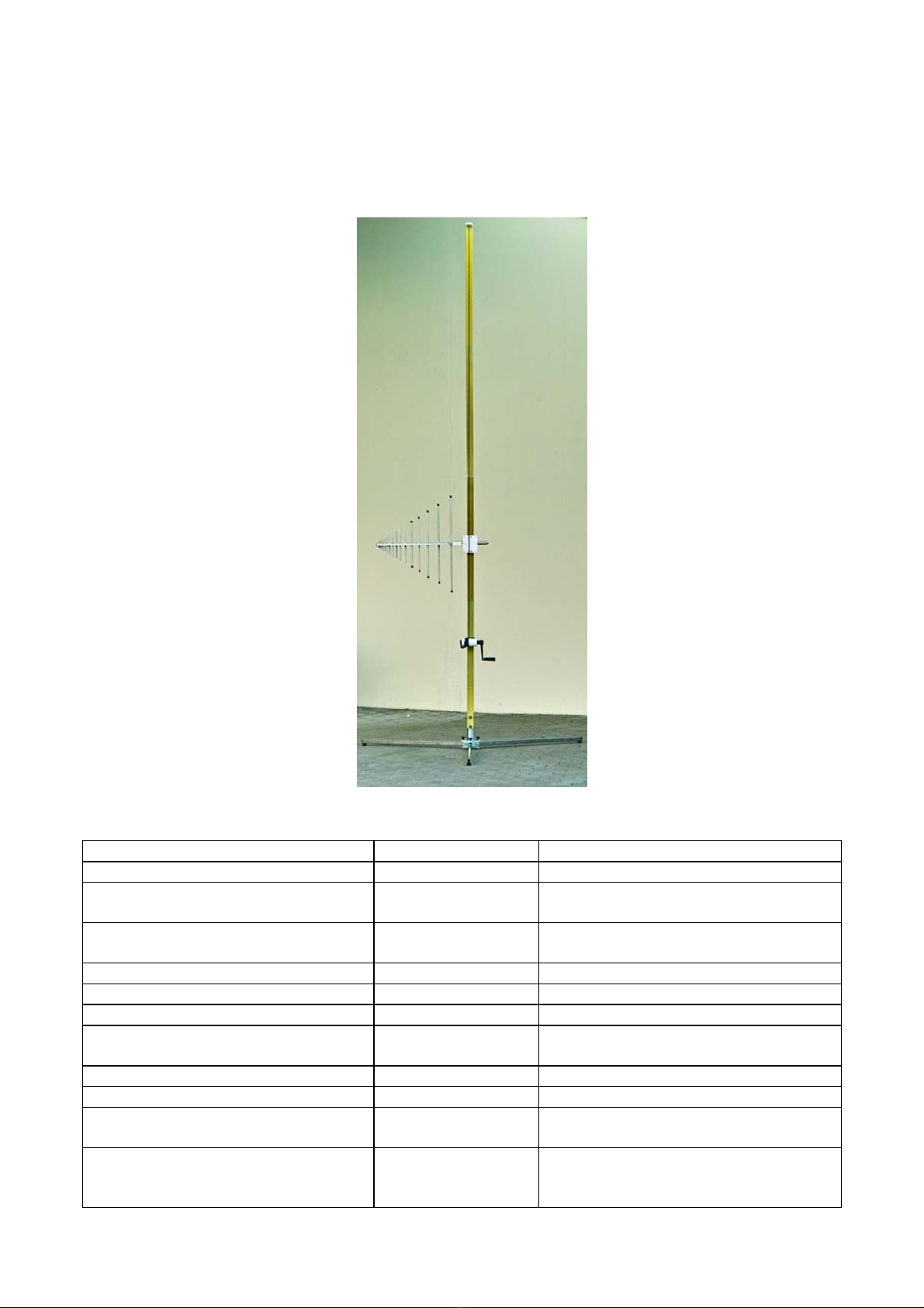
Der Antennenmast AM 9104 wird
hauptsächlich für
Emissionsmessungen eingesetzt,
bei denen häufige
Höhenvariationen erforderlich
sind. Der Mast kann innerhalb
von 2 min auf- oder abgebaut
werden. Durch seine geringen
Transportabmessungen findet er
auch in Kleinwagen genügend
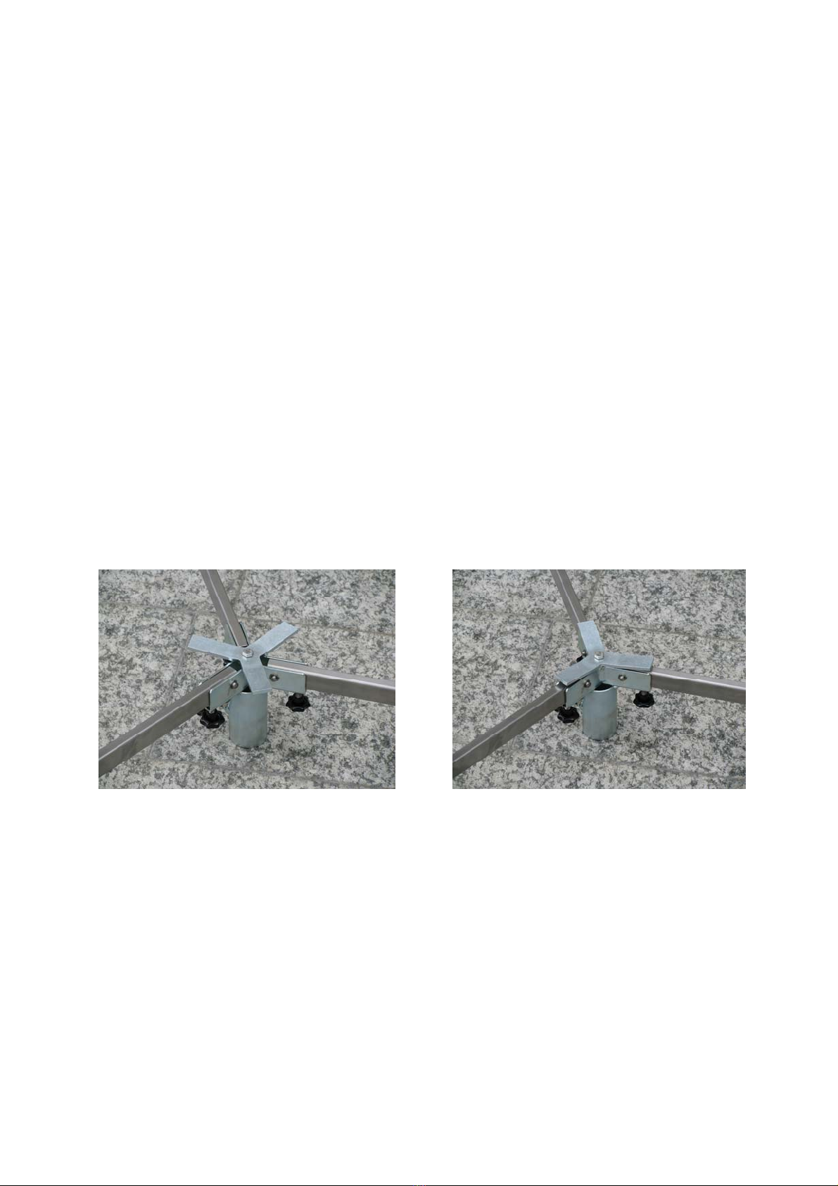
Platz. Die Antennenbefestigung
erfolgt ohne Werkzeug
(Durchstecken des 22 mm
Antennenrohrs und Arretierung
mit Rastring). Zur Aufnahme von
Antennen mit 22 mm Rohr wird
kein zusätzlicher Adapter
benötigt. Mittels einer
eingebauten Wasserwaagen-
Libelle auf dem justierbaren
Dreibeinständer kann auch auf
unebenem Untergrund eine exakt
senkrechte Ausrichtung erreicht
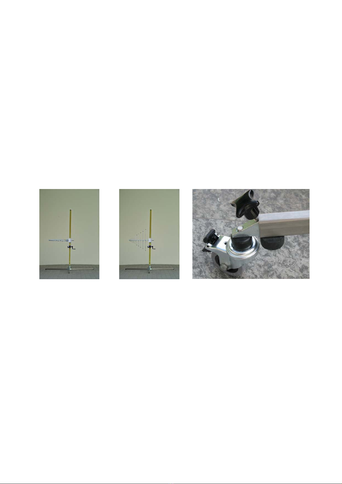
werden. Die Ausleger können mit
bremsbaren Lenkrollen
ausgestattet werden (optional,
Fig. 9).
The main application of AM
9104 is the measurement of
radiated emission with
antennas where frequent
height scans are required. The
mast can be set up and
disassembled without any
tools within 2 minutes. Due to
its small transport dimensions
it can be stored without
problems even in small cars.
The antennas are mounted
with their 22 mm tube and
indexing ring directly into the
antenna support. The
polarisation is fixed by a
latching mechanism in the
antenna support that uses the
indexing ring mounted to any
Schwarzbeck antenna. There
is no additional adapter
needed to accept antennas
with 22 mm tubes. A bubble
level is mounted on the tripod
to enable a convenient
perpendicular adjustment of
the three leg spider on uneven
ground. The spider legs can
be equipped with caster
wheels with brakes optionally
(Fig. 9).
Technische Daten: Specification:
Höhenverstellbereich: 0,4....4,15 m Height scanning range:
Höhenverstellung:
Handkurbelwinde
Height scan:
with manual winch
Dauer für komplettes Durchfahren
der Höhe:
< 8 s Required time for a complete height
scan:
Zeitbedarf zum Aufbau des Mastes: < 2 min Required time for mast assembly:
Gesamtgewicht: 13 kg Total weight:
Transportabmessungen: 1.17 x 0.3 x 0.3 m Dimensions for transport:
Antennenaufnahme:
Für 22 mm Rohr mit Rastring
Antenna support:
For 22 mm tube with indexing ring
Max. Antennengewicht: 5 kg Maximum antenna weight:
Mastfuß-Umkreis-Durchmesser 2.06 m Tripod leg circumcircle diameter:
Material Mast:
Glasfaserverstärkter Kunststoff
Mast material:
Fibre glass
Material Mastfuß:
Stahl verzinkt und Edelstahl,
optional gegen Aufpreis: GFK
Tripod material:
Stainless steel and zinc-plated steel,
optionally (extra cost): Fibre glass
Handbuch Manual Rev. A Seite Page 2
SCHWARZBECK MESS - ELEKTRONIK
An der Klinge 29 D-69250 Schönau Tel.: 06228/1001 Fax.: (49)6228/1003
AM 9104 Antennenmast
AM 9104 Antenna Mast
Lieferumfang:
Scope of delivery:
Der Antennenmast AM 9104 besteht aus einem
Dreibeinständer aus verzinktem Stahl und
Edelstahl, vier GFK–Mastrohren von je 1,15 m
Länge (davon 15 cm Einstecktiefe und 100 cm
freie Länge) und 50 mm Kantenlänge, einer
Handkurbeleinheit mit Seilzug und einem
Antennenwagen aus POM.
AM 9104 consists of a spider-like zinc plated
and stainless steel tripod, 4 glass fiber
square-tubes 50 mm thick of a total length of
115 cm (100 cm later visible, 15 cm used for
the connection to the next tube), a hand
winch, a rope and an antenna support made
of POM.
Boden-Platzbedarf: Required floor space:
Auslegerradius von Mastzentrum: 103 cm.
Minimaler Abstand vom Mastzentrum zur Wand:
52 cm.
Radius from the mast center to the outer leg
end: 103 cm.
Minimum distance between mast center and
wall: 52 cm.
Aufbau des Mastes: Setting up the antenna mast:
1. Dreibeinständer auseinanderfalten und auf
Boden stellen. Verdrehbaren Dreistern unter den
Auslegern in Deckung mit den Auslegerbeinen
bringen (Fig. 1 und Fig. 2).
1. Unfold the steel legs and put the foot to
the ground. Turn the rotatable steel star until
its rays are inline with the screws. (Fig. 1 und
Fig. 2).
Fig. 1 Fig. 2
2. Unterstes Mastrohr mit Metallbund in
Dreibeinhülse stecken und mit
Kreuzgriffschraube arretieren. Dadurch wird
auch Drehung der Mastanlage in der
horizontalen Ebene nach Lösen der Schraube
möglich (Fig. 6).
2. Insert the lowest square tube with its metal
tube into the foot and fix it with the star
handle screw. This screw can be used If the
azimuth of the mast should be changed
without the need to lift the foot. (Fig. 6).
3. Handkurbeleinheit auf unterstes Mastrohr
aufschieben und auf halber Höhe festziehen
(Fig. 3).
3. Shift the hand winch onto the lowest
square tube and fix it in a height of approx.
50 cm (Fig. 3).
Handbuch Manual Rev. A Seite Page 3
SCHWARZBECK MESS - ELEKTRONIK
An der Klinge 29 D-69250 Schönau Tel.: 06228/1001 Fax.: (49)6228/1003
AM 9104 Antennenmast
AM 9104 Antenna Mast
Fig. 3 Fig. 4
4. Kastenförmigen Antennenwagen mit Öse
nach oben auf das Mastrohr aufschieben. Seil
abhaspeln, Knoten am Ende des Seils in Öse
des Antennenwagens einhängen und verriegeln
(Fig. 4).
4. Shift the bird-cage-like antenna support
box onto the lowest square tube. The lug
must be upside. Reel off the rope. Fix the
burl at the end of the rope to the antenna
support lug. (Fig. 4)
5. Die drei übrigen Mastrohre zusammenstecken
und Seil durch die gabelförmigen Schlitze des
Umlenkrollenhalters über die Seilrollen legen
(Fig. 5). Mastrohrabschnitt aufrichten und genau
senkrecht auf Zapfen des untersten Mastrohrs
aufsetzen. Restliches Seil aufwickeln.
Falls nur maximal 3,3 m Gesamthöhe benötigt
werden, kann eines der mittleren Rohre
weggelassen werden. Falls 2,3 m Gesamthöhe
reichen, können 2 mittlere Rohre weggelassen
werden.
5. Shift the other 3 square tubes together
and lay the rope over the rolls as shown in
fig. 5. Errect these 3 pieces and insert them
into the lowest square tube. Roll up the rest
of the rope.
If a total mast height of up to 3.3 m is
sufficient one piece of the square tubes can
be omitted, if 2.3 m are sufficient 2 pieces
can be omitted.
6. Durch die Kreuzgriffschrauben über dem
Stahlstern lassen sich die Ausleger in weiten
Bereichen unebenem Gelände anpassen. Die
eingebaute Wasserwaage ermöglicht das
schnelle Auffinden einer genau senkrechten
Mastposition (Fig. 6).
6. The star handle screws above the steel
star allow to change the height of each single
foot to adapt uneven ground. The built in
bubble level allows the quick detection of an
exact upright position of the mast (Fig. 6).
Fig. 5 Fig. 6
Handbuch Manual Rev. A Seite Page 4
SCHWARZBECK MESS - ELEKTRONIK
An der Klinge 29 D-69250 Schönau Tel.: 06228/1001 Fax.: (49)6228/1003
AM 9104 Antennenmast
AM 9104 Antenna Mast
7. Antenne installieren. Der Antennenwagen
trägt seitlich eine Kugelrastvorrichtung, die nach
dem Einschieben des Antennentragrohres in
einer ringförmigen Nut einrastet. In
Winkelabständen von je 90° erfolgt auch eine
schwache zusätzliche Drehrastung. Sie
ermöglicht ein Verdrehen der
Polarisationsebene mit sehr geringem
Kraftaufwand (Fig.7 und Fig. 8). Die Rastung ist
nicht geeignet für Antennen, die ein hohes
Moment im Bezug auf ihre Drehachse ausüben.
Dies ist bei Antennen der Fall, deren Drehachse
außerhalb des Schwerpunkts liegt. Adapter für
Antennen anderer Hersteller auf AM 9104 sind
auf Anfrage erhältlich.
7. Install the antenna. The antenna support
box has a latching mechanism. Insert the
antenna into the latching mechanism. A steel
ball holds the notch in the indexing ring of
the antenna. Every 90 degrees the latching
mechanism provides rotational indexing. This
allows a fast and precise change of the
antenna polarisation (Fig.7 und Fig. 8). The
latching mechanism is not suitable for
antennas with high torque caused by a
fixture outside of the rotational center.
Adapters to fix antennas of other
manufacturers on an AM 9104 are available
on request.
Fig. 7 Fig. 8 Lenkrollen wheels (optional) Fig. 9.
Verwendung im Freien: Outdoor usage:
Die Mastanlage ist für begrenzte Zeit
regenunempfindlich. Ein längeres Verbleiben im
Freien ist jedoch nicht empfehlenswert, da die
Lager darunter leiden könnten. Außer
gelegentlichem Ölen der Lager und Gelenke ist
die Anlage wartungsfrei. Auch die Stahlkugel der
Rastvorrichtung sollte gelegentlich eingefettet
werden.
The mast can be used outside. Rain for a
limited time will not destroy the mast. A
permanent outdoor installation is not
recommended as the bearings may suffer.
The bearings should be greased with oil and
the steel ball of the latching mechanism
should be protected with grease from time to
time.
Sicherheit: Safety:
Die Mastanlage darf nur nach Einweisung
verwendet werden. Blitzgefahr, Gefahren durch
Umstürzen von Antennen oder Berühren
spannungsführender Leitungen müssen
berücksichtigt werden!
The mast AM 9104 may only be used by
trained staff. Dangers may occur by
lightning, tumbling, or touching high voltage
cables. The user must be aware of these
dangers before using the mast!

Other Schwarzbeck Antenna manuals

Schwarzbeck FMZB 1512 User manual

Schwarzbeck

Schwarzbeck FMZB 1512 User manual

Schwarzbeck EFS 9219 User manual

Schwarzbeck

Schwarzbeck EFS 9219 User manual

Schwarzbeck HXYZ 9170 User manual

Schwarzbeck

Schwarzbeck HXYZ 9170 User manual

Schwarzbeck XSLP 9142 User manual

Schwarzbeck

Schwarzbeck XSLP 9142 User manual

Schwarzbeck VAMP 9243 User manual

Schwarzbeck

Schwarzbeck VAMP 9243 User manual

Popular Antenna manuals by other brands

ESCO Technologies ETS-Lindgren 3109 user manual

ESCO Technologies

ESCO Technologies ETS-Lindgren 3109 user manual

Hi-Z Antennas Hi-Z 8A-160 manual

Hi-Z Antennas

Hi-Z Antennas Hi-Z 8A-160 manual

König Electronic KN-DVBT-IN90LT manual

König Electronic

König Electronic KN-DVBT-IN90LT manual

Hy-Gain 18HTjr manual

Hy-Gain

Hy-Gain 18HTjr manual

Hy-Gain LJ-115 instruction manual

Hy-Gain

Hy-Gain LJ-115 instruction manual

CommScope CMAX-OMF8-43-UWI53 Installation instruction

CommScope

CommScope CMAX-OMF8-43-UWI53 Installation instruction

DX Engineering DXE-AOK-17M quick start guide

DX Engineering

DX Engineering DXE-AOK-17M quick start guide

DIGITIZE Dipole-Lo manual

DIGITIZE

DIGITIZE Dipole-Lo manual

Tonna F9FT Assembly instructions

Tonna

Tonna F9FT Assembly instructions

GE 24763 user manual

GE

GE 24763 user manual

Beam RST703 installation guide

Beam

Beam RST703 installation guide

Javad 99-587303-01 instructions

Javad

Javad 99-587303-01 instructions

Avocent Emerge HGA51G-DIR30 Quick installation guide

Avocent

Avocent Emerge HGA51G-DIR30 Quick installation guide

Iridium Pilot TPIM1301 installation guide

Iridium

Iridium Pilot TPIM1301 installation guide

Sea Tel Base Exit quick start guide

Sea Tel

Sea Tel Base Exit quick start guide

Greentek LDP-UV32N installation manual

Greentek

Greentek LDP-UV32N installation manual

Sirio Antenne 2108801.00 manual

Sirio Antenne

Sirio Antenne 2108801.00 manual

Ebyte TXWF-PCB-3214 user manual

Ebyte

Ebyte TXWF-PCB-3214 user manual

manuals.online logo
manuals.online logoBrands
  • About & Mission
  • Contact us
  • Privacy Policy
  • Terms and Conditions

Copyright 2025 Manuals.Online. All Rights Reserved.