Ficosa TCU-FITAX-3.5 User manual

Project
DATE
22/06/20
TCU-FITAX-3.5
FCC Certification
REFERENCE
LEVEL
V01.04
SHEET
1/45
Link to TOP INDEX
BY
MVT
Version:
V01.00
V01.01
V01.02
V01.03
V01.04
Author:
MVT
MVT
MVT
MVT
MVT
Date:
23/03/20
11/05/20
20/05/20
22/05/20
22/06/20
FICOSA INTERNATIONAL S.A. 2016. This document or its contents may not be communicated
or distributed to third parties or reproduced in whole or in part without the express permission of FICOSA
TCU-FITAX-3.5
DSRC OBU User Manual
Version 01.04

Project
DATE
22/06/20
TCU-FITAX-3.5
FCC Certification
REFERENCE
LEVEL
V01.04
SHEET
2/45
Link to TOP INDEX
BY
MVT
Version:
V01.00
V01.01
V01.02
V01.03
V01.04
Author:
MVT
MVT
MVT
MVT
MVT
Date:
23/03/20
11/05/20
20/05/20
22/05/20
22/06/20
FICOSA INTERNATIONAL S.A. 2016. This document or its contents may not be communicated
or distributed to third parties or reproduced in whole or in part without the express permission of FICOSA
Revision History:
Date
Version
Description
23/03/2020
V01.00
First Draft
11/05/2020
V01.01
Added Review Comments:
Section 2.2 –Label Design modified to include
Part name, Model Name, FCC ID and FCC Id of
the LTE Module.
Section 2.5 –Added information related to
maximum gain for a permitted Antenna.
Section 10.1 –Added Details for a “Permitted
Antenna”
20/05/2020
V01.02
Updates following review comments:
Section 10.1 –Remove Antenna Type
information from table.
Section 10.1 –Include Max Gain Data for GSM,
WCDMA, and LTE Technology.
Section 10.1 –Include Unlicensed Bands
information.
Section 5.1 –Remove PCB Photo.
22/05/20
V01.03
Updates following review comments:
Section 10.1 –Added comment
about operational mode of DSRC channels.
22/06/20
V01.04
Updates following review comments:
Section 10.3 –Update Regulatory Information
to reflect Class A compliance.

Project
DATE
22/06/20
TCU-FITAX-3.5
FCC Certification
REFERENCE
LEVEL
V01.04
SHEET
3/45
Link to TOP INDEX
BY
MVT
Version:
V01.00
V01.01
V01.02
V01.03
V01.04
Author:
MVT
MVT
MVT
MVT
MVT
Date:
23/03/20
11/05/20
20/05/20
22/05/20
22/06/20
FICOSA INTERNATIONAL S.A. 2016. This document or its contents may not be communicated
or distributed to third parties or reproduced in whole or in part without the express permission of FICOSA
LIST OF CONTENTS
1. INTRODUCTION ......................................................................................................................................6
2. DSRC OBU SYSTEM DESCRIPTION....................................................................................................6
2.1 DSRC OBU -GENERAL ASSEMBLY OVERVIEW.......................................................................................6
2.2 DSRC OBU -LABEL DETAILS..................................................................................................................8
2.3 DSRC OBU -EXTERNAL DIMENSIONS.....................................................................................................9
2.4 DSRC OBU -BOARDS..............................................................................................................................9
2.5 DSRC OBU -SYSTEM ARCHITECTURE OVERVIEW ..................................................................................9
2.6 DSRC OBU –INTERFACES DESCRIPTION...............................................................................................11
2.6.1 MAIN Connector Pin-Out .................................................................................................12
2.6.2 HMI & CAN Connector Pin-Out.......................................................................................13
3. ELECTRICAL CHARACTERISTICS ..................................................................................................14
4. DSRC OBU POWER UP PROCEDURE ...............................................................................................15
5. DSRC OBU BOOT UP PROCEDURE...................................................................................................16
5.1 CONNECTING TO THE UNIT .....................................................................................................................16
5.2 DSRC OBU SOFTWARE VERSION ..........................................................................................................16
5.3 ADB.......................................................................................................................................................17
5.4 GNSS FIX ACQUISITION .........................................................................................................................17
5.5 BASIC SAFETY MESSAGE ........................................................................................................................18
5.6 CONNECTING TO THE HMI BOARD WITH ADB OVER USB......................................................................19
5.7 ANDROID SDK........................................................................................................................................19
5.8 GETTING ANDROID SDK FOR LINUX ......................................................................................................19
5.9 SET SDK ENVIRONMENT VAR .................................................................................................................20
6. CAPTURING BASIC SAFETY MESSAGES........................................................................................21
7. DSRC OBU - SAFETY APPLICATIONS..............................................................................................22
7.1 EMERGENCY ELECTRONIC BRAKE LIGHTS (EEBL) ................................................................................22
7.2 FORWARD COLLISION WARNING (FCW)................................................................................................22
7.3 BLIND SPOT WARNING/LANE CHANGE WARNING (BSW/LCW)............................................................24
7.4 DO NOT PASS WARNING (DNPW)..........................................................................................................25
7.5 INTERSECTION MOVEMENT ASSIST (IMA)..............................................................................................26
7.6 LEFT TURN ASSIST (LTA) ......................................................................................................................27
7.7 RIGHT TURN ASSIST (RTA)....................................................................................................................27
7.8 SPEED LIMIT WARNING /CURVE SPEED WARNING (SPD/CSW)............................................................28
8. DEAD RECKONING...............................................................................................................................29
9. VEHICLE INTEGRATION ....................................................................................................................30
9.1 DSRC OBU -MECHANICAL VEHICLE INTEGRATION..............................................................................30
9.2 DSRC OBU -ELECTRICAL VEHICLE INTEGRATION................................................................................30
9.3 VIRTUAL CAN PROTOCOL......................................................................................................................31
10. REGULATORY INFORMATION USA ................................................................................................35
10.1 PERMITTED ANTENNA........................................................................................................................35
10.2 RF EXPOSURE SAFETY........................................................................................................................36
10.3 FCC STATEMENT ...............................................................................................................................36
11. ANNEX #1.................................................................................................................................................38
11.1 HOST A HOTSPOT ...............................................................................................................................38

Project
DATE
22/06/20
TCU-FITAX-3.5
FCC Certification
REFERENCE
LEVEL
V01.04
SHEET
4/45
Link to TOP INDEX
BY
MVT
Version:
V01.00
V01.01
V01.02
V01.03
V01.04
Author:
MVT
MVT
MVT
MVT
MVT
Date:
23/03/20
11/05/20
20/05/20
22/05/20
22/06/20
FICOSA INTERNATIONAL S.A. 2016. This document or its contents may not be communicated
or distributed to third parties or reproduced in whole or in part without the express permission of FICOSA
11.2 ENABLING FORWARDING ON SC20 ....................................................................................................39
11.3 MQTT API ........................................................................................................................................39

Project
DATE
22/06/20
TCU-FITAX-3.5
FCC Certification
REFERENCE
LEVEL
V01.04
SHEET
5/45
Link to TOP INDEX
BY
MVT
Version:
V01.00
V01.01
V01.02
V01.03
V01.04
Author:
MVT
MVT
MVT
MVT
MVT
Date:
23/03/20
11/05/20
20/05/20
22/05/20
22/06/20
FICOSA INTERNATIONAL S.A. 2016. This document or its contents may not be communicated
or distributed to third parties or reproduced in whole or in part without the express permission of FICOSA
Acronyms
OBU
On Board Unit
DSRC
Dedicated Short Range Communications
V2X
Vehicle-To-Everything
HV
Host Vehicle
RV
Remote Vehicle
EEBL
Emergency Electronic Brake Lights
FCW
Forward Collision Warning
BSW
Blind Spot Warning
LCW
Lane Change Warning
DNPW
Do Not Pass Warning
IMA
Intersection Movement Assist
LTA
Left Turn Assist
RTA
Right Turn Assist
SPD
Speed Limit Warning
CSW
Curve Speed Warning
Project
DATE
22/06/20
TCU-FITAX-3.5
FCC Certification
REFERENCE
LEVEL
V01.04
SHEET
6/45
Link to TOP INDEX
BY
MVT
Version:
V01.00
V01.01
V01.02
V01.03
V01.04
Author:
MVT
MVT
MVT
MVT
MVT
Date:
23/03/20
11/05/20
20/05/20
22/05/20
22/06/20
FICOSA INTERNATIONAL S.A. 2016. This document or its contents may not be communicated
or distributed to third parties or reproduced in whole or in part without the express permission of FICOSA
1.Introduction
The purpose of this document is to describe and list all the functionalities and
capabilities of DSRC OBU from an end user point of view.
The acronyms DSRC stands for “Dedicated Short Range Communications” which is
the technology that allows V2X communications based on Standard 802.11p.
The following data is related to the DSRC OBU for what concerns FCC Certification.
Model Name: TCU-FITAX-3.5
FCC ID: 2AVOU-AAA2020FTX35
In addition, the Main Board contains an LTE Module with P/N being SC20ASA-8GB-STD,
the FCC ID of which is: XMR201706SC20A
2.DSRC OBU System Description
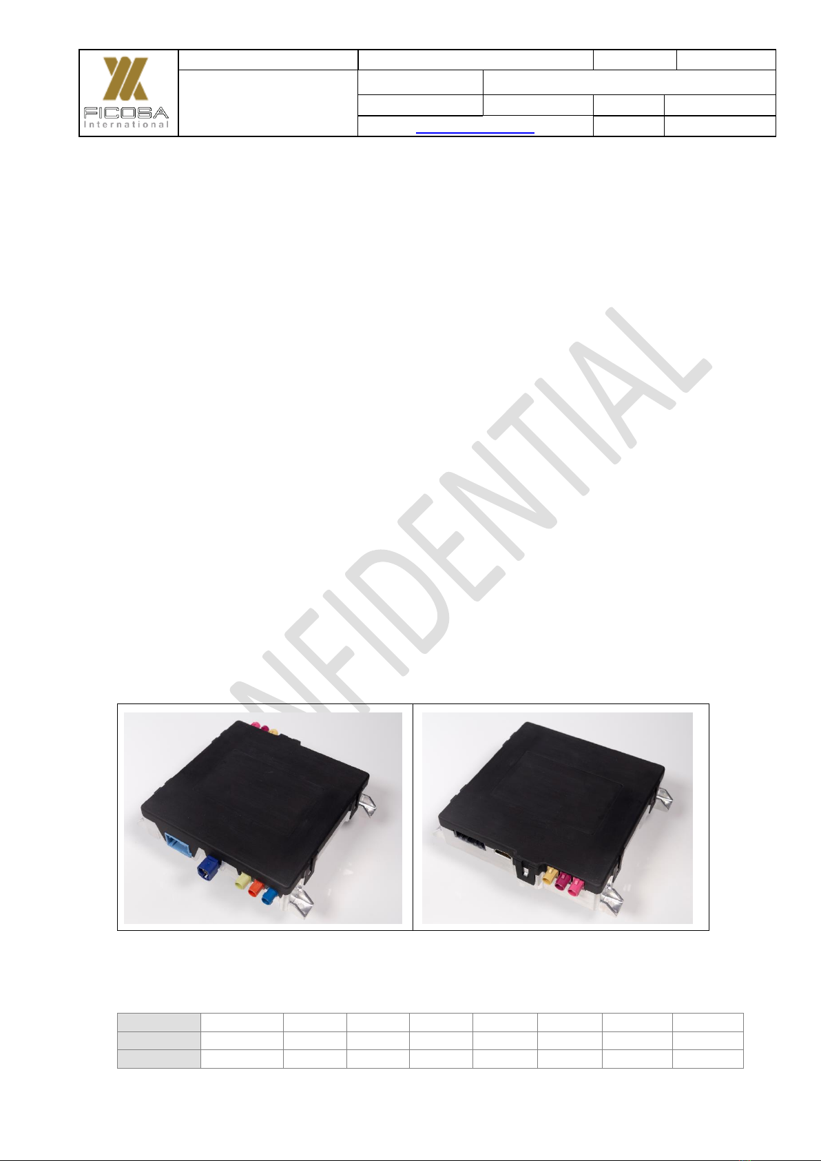
2.1 DSRC OBU - General Assembly Overview
The following pictures show an overview of the DSRC On-Board-Unit from Top and
Bottom Side.
Figure 1. Top View of the DSRC Units (Plastic side).

Project
DATE
22/06/20
TCU-FITAX-3.5
FCC Certification
REFERENCE
LEVEL
V01.04
SHEET
7/45
Link to TOP INDEX
BY
MVT
Version:
V01.00
V01.01
V01.02
V01.03
V01.04
Author:
MVT
MVT
MVT
MVT
MVT
Date:
23/03/20
11/05/20
20/05/20
22/05/20
22/06/20
FICOSA INTERNATIONAL S.A. 2016. This document or its contents may not be communicated
or distributed to third parties or reproduced in whole or in part without the express permission of FICOSA
Figure 2. Bottom View of the DSRC Units (Metal side)
The OBU Bottom side is made of metallic material in order to ease thermal dissipation
of the most critical components.
In addition, below is shown a breakdown of the DSRC OBU Mechanical Assembly
along with the weight for each individual item.
Figure 3. DSRC OBU Mechanical Breakdown and Weight
The Total Weight of the Unit is 470 g.
Project
DATE
22/06/20
TCU-FITAX-3.5
FCC Certification
REFERENCE
LEVEL
V01.04
SHEET
8/45
Link to TOP INDEX
BY
MVT
Version:
V01.00
V01.01
V01.02
V01.03
V01.04
Author:
MVT
MVT
MVT
MVT
MVT
Date:
23/03/20
11/05/20
20/05/20
22/05/20
22/06/20
FICOSA INTERNATIONAL S.A. 2016. This document or its contents may not be communicated
or distributed to third parties or reproduced in whole or in part without the express permission of FICOSA
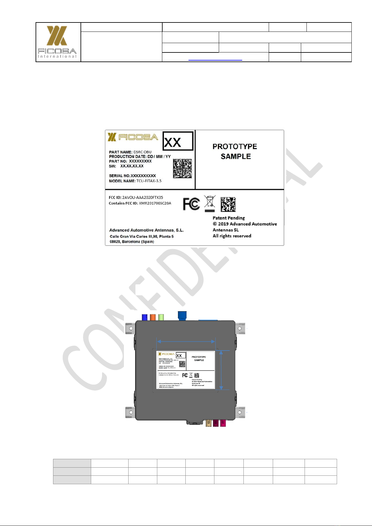
2.2 DSRC OBU - Label Details
The template of the DSRC OBU label is captured in Figure 4 along with the relevant
dimensions.
Figure 4. DSRC OBU Label Description
There is a specific area on the Top Side of the DSRC OBU to allocate the Label as
shown below.
Figure 5. DSRC OBU Label Placement and Dimensions
85 ± 0.5 mm
55 ± 0.5 mm

Project
DATE
22/06/20
TCU-FITAX-3.5
FCC Certification
REFERENCE
LEVEL
V01.04
SHEET
9/45
Link to TOP INDEX
BY
MVT
Version:
V01.00
V01.01
V01.02
V01.03
V01.04
Author:
MVT
MVT
MVT
MVT
MVT
Date:
23/03/20
11/05/20
20/05/20
22/05/20
22/06/20
FICOSA INTERNATIONAL S.A. 2016. This document or its contents may not be communicated
or distributed to third parties or reproduced in whole or in part without the express permission of FICOSA
2.3 DSRC OBU - External Dimensions
Below are shown the overall dimensions of the DSRC OBU.
Figure 6. DSRC OBU Overall Dimensions
2.4 DSRC OBU - Boards
The DSRC OBU consist of two boards:
Main Board: This Board provides the V2X Communications capability. It
contains mainly the Main Processor, the RF Front-End, GNSS Receiver and
Power Management.
HMI Board: The HMI Board provides the Wifi/BT, LTE connectivity, HDMI,
Audio and Ethernet interfaces as well as CAN interfaces. In addition, it includes
an Android Microprocessor to develop 3er Party Applications.
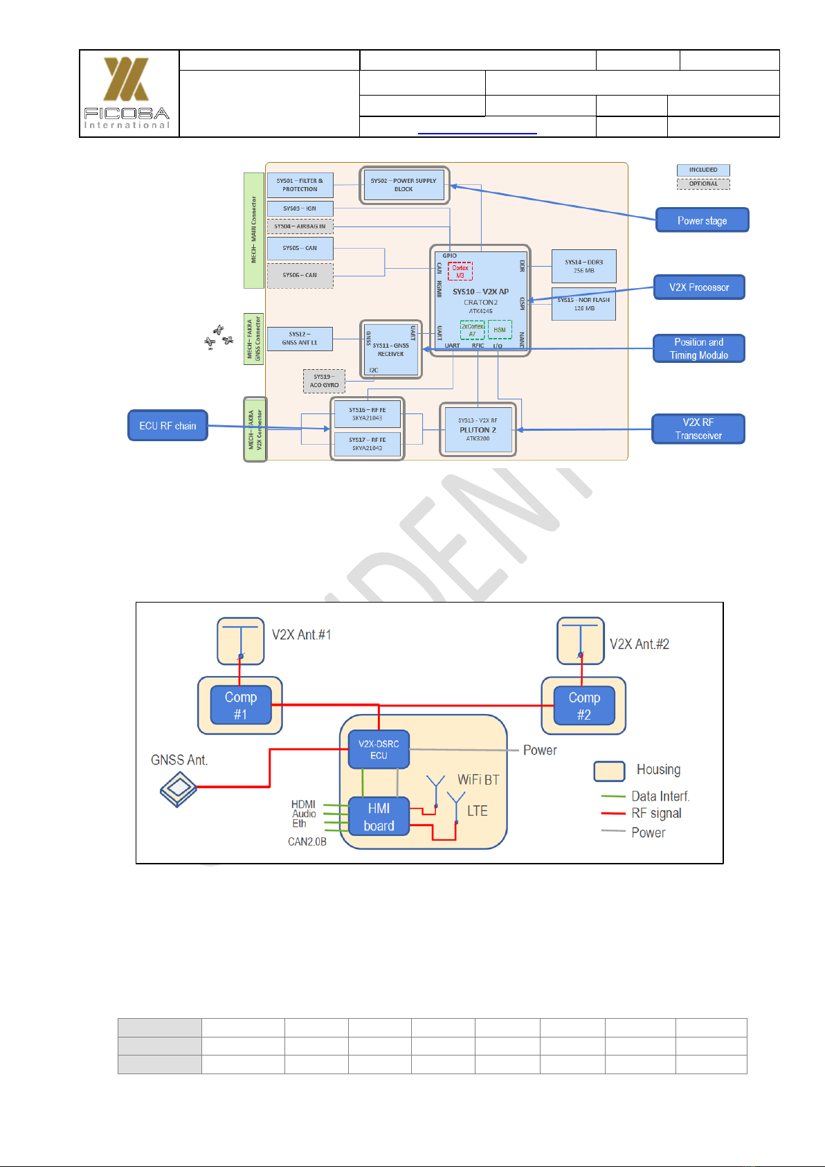
2.5 DSRC OBU - System Architecture Overview
The below picture shows the System Architecture of the V2X Main Board.
Project
DATE
22/06/20
TCU-FITAX-3.5
FCC Certification
REFERENCE
LEVEL
V01.04
SHEET
10/45
Link to TOP INDEX
BY
MVT
Version:
V01.00
V01.01
V01.02
V01.03
V01.04
Author:
MVT
MVT
MVT
MVT
MVT
Date:
23/03/20
11/05/20
20/05/20
22/05/20
22/06/20
FICOSA INTERNATIONAL S.A. 2016. This document or its contents may not be communicated
or distributed to third parties or reproduced in whole or in part without the express permission of FICOSA
Figure 7. Main Board System Architecture
The following Figure shows the Architecture of the OBU as Assembly, V2X Main
Board + HMI Board.
Figure 8. DSRC OBU System Architecture (Main + HMI Board)
Although the Antennas are shown in the above diagram to aid understanding of the
overall system, these particular items are not supplied as part of DSRC OBU Product.
The OBU will provision Antenna Interfaces but the Antennas themselves are
responsibility of the party in charge of vehicle integration.

Project
DATE
22/06/20
TCU-FITAX-3.5
FCC Certification
REFERENCE
LEVEL
V01.04
SHEET
11/45
Link to TOP INDEX
BY
MVT
Version:
V01.00
V01.01
V01.02
V01.03
V01.04
Author:
MVT
MVT
MVT
MVT
MVT
Date:
23/03/20
11/05/20
20/05/20
22/05/20
22/06/20
FICOSA INTERNATIONAL S.A. 2016. This document or its contents may not be communicated
or distributed to third parties or reproduced in whole or in part without the express permission of FICOSA
If the device operates in the specified bands (as per Section 10.1), an Antenna with
maximum gain of 3dBi must be used.
2.6 DSRC OBU –Interfaces Description
Below are identified all the interfaces of the DSRC OBUs.
There are ten external interfaces:
Main connector
Ethernet BroadR-Reach
GNSS (active antenna with phantom feeding)
V2X Channel 0
V2X Channel 1
LTE 1
LTE 2
WiFi/Bluetooth
HDMI
CAN
Figure 9. DSRC OBU Interfaces

Project
DATE
22/06/20
TCU-FITAX-3.5
FCC Certification
REFERENCE
LEVEL
V01.04
SHEET
12/45
Link to TOP INDEX
BY
MVT
Version:
V01.00
V01.01
V01.02
V01.03
V01.04
Author:
MVT
MVT
MVT
MVT
MVT
Date:
23/03/20
11/05/20
20/05/20
22/05/20
22/06/20
FICOSA INTERNATIONAL S.A. 2016. This document or its contents may not be communicated
or distributed to third parties or reproduced in whole or in part without the express permission of FICOSA
Figure 10. DSRC OBU Interfaces
2.6.1 MAIN Connector Pin-Out
The main connector provides the OBU a direct line from the Vehicle Battery of 12
Volts, it can also be connected to the Ignition line for IGN based wake-up of the OBU.
Below are shown the Pin_Out Details of the Main Connector.

Project
DATE
22/06/20
TCU-FITAX-3.5
FCC Certification
REFERENCE
LEVEL
V01.04
SHEET
13/45
Link to TOP INDEX
BY
MVT
Version:
V01.00
V01.01
V01.02
V01.03
V01.04
Author:
MVT
MVT
MVT
MVT
MVT
Date:
23/03/20
11/05/20
20/05/20
22/05/20
22/06/20
FICOSA INTERNATIONAL S.A. 2016. This document or its contents may not be communicated
or distributed to third parties or reproduced in whole or in part without the express permission of FICOSA
Figure 11. Main Connector Pin-Out
2.6.2 HMI & CAN Connector Pin-Out
The HMI/CAN Connector provides the OBU connection to the Internal CAN Network
of the vehicle, it can also be used to map audio and microphone.
Figure 12. HMI/CAN Connector Pin-Out

Project
DATE
22/06/20
TCU-FITAX-3.5
FCC Certification
REFERENCE
LEVEL
V01.04
SHEET
14/45
Link to TOP INDEX
BY
MVT
Version:
V01.00
V01.01
V01.02
V01.03
V01.04
Author:
MVT
MVT
MVT
MVT
MVT
Date:
23/03/20
11/05/20
20/05/20
22/05/20
22/06/20
FICOSA INTERNATIONAL S.A. 2016. This document or its contents may not be communicated
or distributed to third parties or reproduced in whole or in part without the express permission of FICOSA
3. Electrical Characteristics
Min
Typ
Max
Units
Operating temperature range
-40
25
70
ºC
Operating voltage range
9
12
18
V
Current consumption ON mode
[Vin=12V8, T=25ºC]
Average
-
446
-
mA
Peak
383
-
813
mA
Current consumption BOOTA mode
[Vin=12V8, T=25ºC]
Average
-
161
-
mA
Peak
149
-
179
mA
Current consumption BOOTB mode
[Vin=12V8, T=25ºC]
Average
-
412
-
mA
Peak
193
-
780
mA
Current consumption OFF mode
-
-
3,4
mA
Project
DATE
22/06/20
TCU-FITAX-3.5
FCC Certification
REFERENCE
LEVEL
V01.04
SHEET
15/45
Link to TOP INDEX
BY
MVT
Version:
V01.00
V01.01
V01.02
V01.03
V01.04
Author:
MVT
MVT
MVT
MVT
MVT
Date:
23/03/20
11/05/20
20/05/20
22/05/20
22/06/20
FICOSA INTERNATIONAL S.A. 2016. This document or its contents may not be communicated
or distributed to third parties or reproduced in whole or in part without the express permission of FICOSA
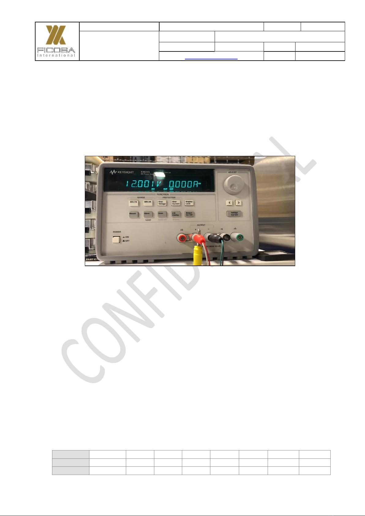
4. DSRC OBU Power up Procedure
The DSRC OBU must be powered up at 12 V. In case the maximum Amperage was
to be limited, it would be set, at least, to 1 A. Note that positive (Red), IGN Line (Blue)
and negative (Black) line connectors must be plugged to the power source as shown
below.
Figure 13. DSRC OBU Power up using Power Supply
Project
DATE
22/06/20
TCU-FITAX-3.5
FCC Certification
REFERENCE
LEVEL
V01.04
SHEET
16/45
Link to TOP INDEX
BY
MVT
Version:
V01.00
V01.01
V01.02
V01.03
V01.04
Author:
MVT
MVT
MVT
MVT
MVT
Date:
23/03/20
11/05/20
20/05/20
22/05/20
22/06/20
FICOSA INTERNATIONAL S.A. 2016. This document or its contents may not be communicated
or distributed to third parties or reproduced in whole or in part without the express permission of FICOSA
5. DSRC OBU Boot Up Procedure
This Section provides a detailed Functionality of the Booting Procedure.
The DSRC OBU Platform operates in the 5.9GHz range with the capacity to construct,
Tx and Rx Basic Safety Messages (BSM) compliant with standard SAE J2735.
5.1Connecting to the Unit
Note: This Section will be updated, since currently it is focused on debugging mode
rather than from an end user point of view.
The DSRC OBU has a Serial (RS232) Port on the Main Board that is used to connect
the to the OBU via any suitable terminal (Linux) or Teraterm/Putty(Windows).
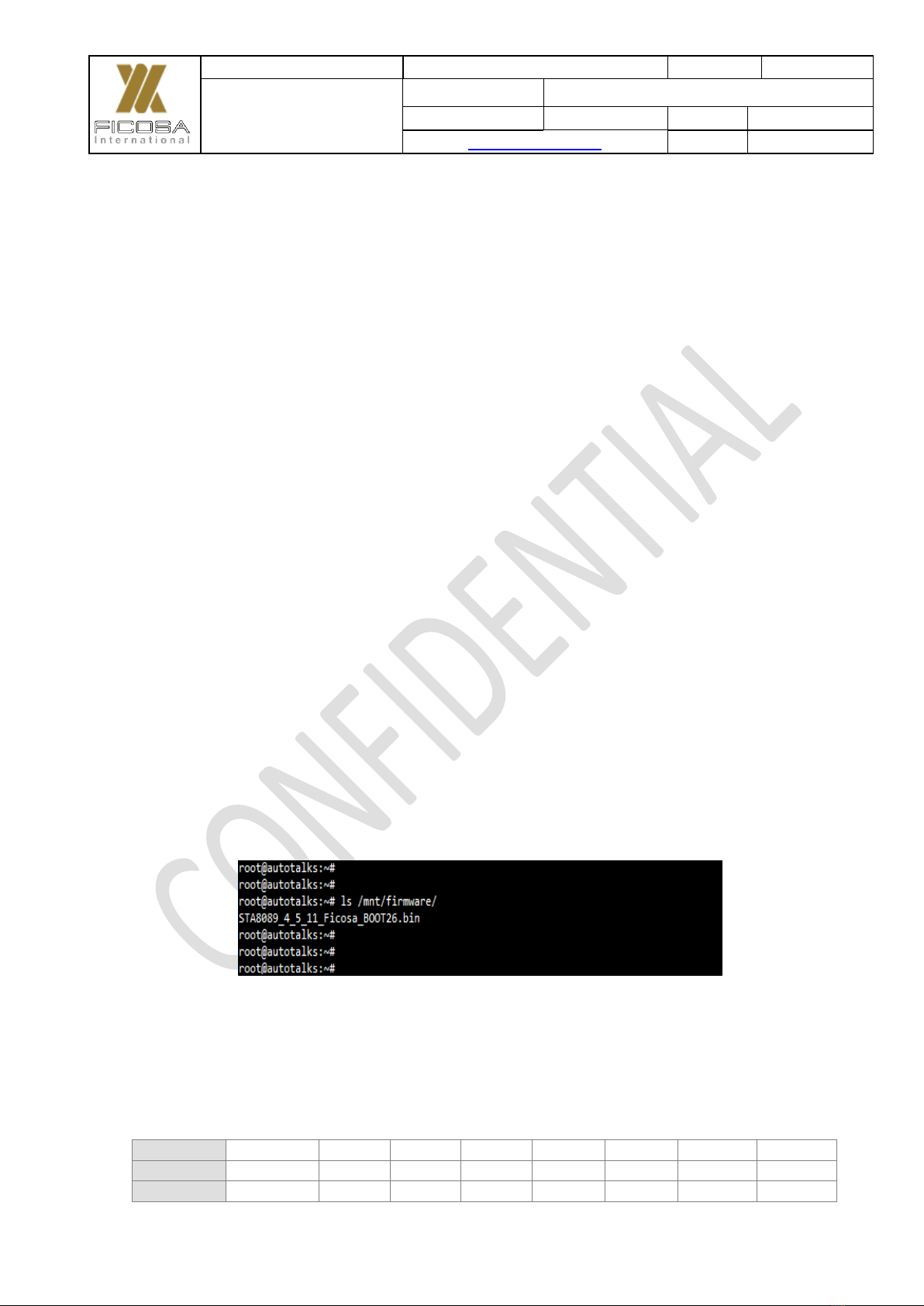
5.2DSRC OBU Software Version
Once connected to the OBU it is recommended to check the software version of the
OBU. The SW version information from the OBU can be retrieved using the following
command: cat /mnt/firmware/versions
This command returns the specific firmware version active on each of the
Microcontrollers.
Figure 14. DSRC OBU SW Version

Project
DATE
22/06/20
TCU-FITAX-3.5
FCC Certification
REFERENCE
LEVEL
V01.04
SHEET
17/45
Link to TOP INDEX
BY
MVT
Version:
V01.00
V01.01
V01.02
V01.03
V01.04
Author:
MVT
MVT
MVT
MVT
MVT
Date:
23/03/20
11/05/20
20/05/20
22/05/20
22/06/20
FICOSA INTERNATIONAL S.A. 2016. This document or its contents may not be communicated
or distributed to third parties or reproduced in whole or in part without the express permission of FICOSA
5.3ADB
The HMI Board has ADB for communication between the PC or Main Processor.
Figure 15. ADB Devices Connected to Main Processor
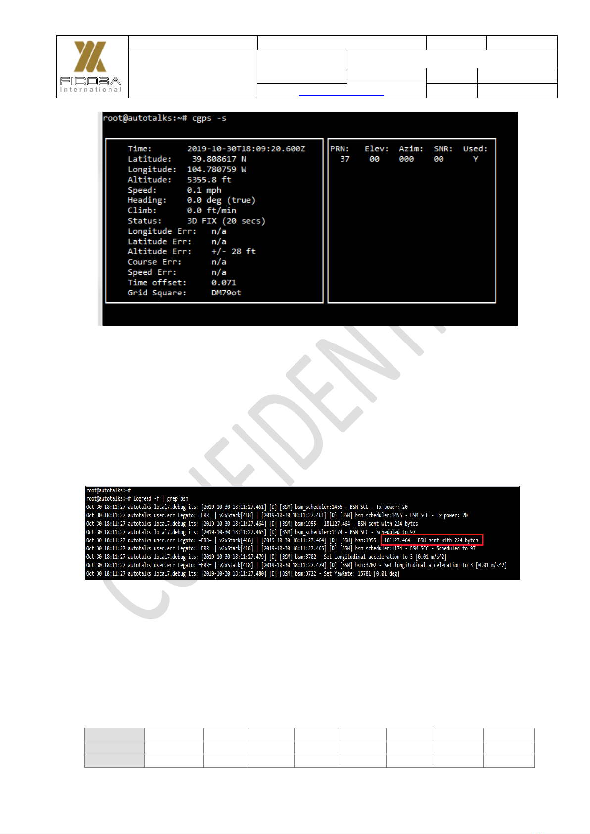
5.4GNSS Fix Acquisition
The GNSS Receiver is responsible to provide accurate GPS information to the Main
Processor, for construction of a meaningful BSM.
The Unit has to get a GPS fix in GNSS Receiver (Refer to SYS-11 in Figure 7) module.
It is possible to monitor the fix is acquired via MQTT Channels or the cpgps api of
GNSS Receiver.
The command to be used is “mosquito_sub –t GNSS_Event” / “cgps -s”
Project
DATE
22/06/20
TCU-FITAX-3.5
FCC Certification
REFERENCE
LEVEL
V01.04
SHEET
18/45
Link to TOP INDEX
BY
MVT
Version:
V01.00
V01.01
V01.02
V01.03
V01.04
Author:
MVT
MVT
MVT
MVT
MVT
Date:
23/03/20
11/05/20
20/05/20
22/05/20
22/06/20
FICOSA INTERNATIONAL S.A. 2016. This document or its contents may not be communicated
or distributed to third parties or reproduced in whole or in part without the express permission of FICOSA
Figure 16. Example of GNSS Fix
5.5Basic Safety Message
In order to monitor BSM, the recommended way is to monitor system logs.
Command: logread –f | grep –i bsm
Figure 17. System Log showing Transmission of BSM’s
Note: For Tx or Rx of BSM it is necessary to acquire GPS Fix and also for the unit to
have a valid certificate.

Project
DATE
22/06/20
TCU-FITAX-3.5
FCC Certification
REFERENCE
LEVEL
V01.04
SHEET
19/45
Link to TOP INDEX
BY
MVT
Version:
V01.00
V01.01
V01.02
V01.03
V01.04
Author:
MVT
MVT
MVT
MVT
MVT
Date:
23/03/20
11/05/20
20/05/20
22/05/20
22/06/20
FICOSA INTERNATIONAL S.A. 2016. This document or its contents may not be communicated
or distributed to third parties or reproduced in whole or in part without the express permission of FICOSA
5.6Connecting to the HMI board with ADB over USB
The DSRC OBU provides an external interface as shown in Figure 2, to connect to
the HMI board with ADB via the HMI USB interface.
Figure 18. Interface to connect to HMI Board and ADB
Note: It is necessary to have the latest version of adb and fastboot drivers to be
installed on the host PC.
The HMI board has a single USB connection, so it is either connected to the Main
Processor or to the PC (disconnected from the Main Processor). Once the connection
is established, using this interface it is possible to host a hotspot and enable
forwarding to the HMI board following the procedure described in the Annex 11.
5.7Android SDK
The HMI module is running Android version 7.1.2 Nougat. This version of Android
corresponds to API level 25. To start developing applications for this platform, we will
need the Android SDK consisting of a set of command line tools, build tools and
platform sources.
5.8Getting Android SDK for Linux
Download Android SDK tools for Linux from: https://developer.android.com/studio
Open a terminal and go to the directory where the file has been downloaded.
Decompress the zip file and go to the uncompressed folder directory. This directory
will be our new SDK folder. At this point, only SDK tools are available, so the next step

Project
DATE
22/06/20
TCU-FITAX-3.5
FCC Certification
REFERENCE
LEVEL
V01.04
SHEET
20/45
Link to TOP INDEX
BY
MVT
Version:
V01.00
V01.01
V01.02
V01.03
V01.04
Author:
MVT
MVT
MVT
MVT
MVT
Date:
23/03/20
11/05/20
20/05/20
22/05/20
22/06/20
FICOSA INTERNATIONAL S.A. 2016. This document or its contents may not be communicated
or distributed to third parties or reproduced in whole or in part without the express permission of FICOSA
is to get the rest of necessary things to build an Android app. Run the following
commands from the root of the SDK to get all the necessary sources and tools to start
using Android SDK in Linux:
Download and install platform sources for API level 25:
$ tools/bin/sdkmanager "platforms;android-25”
Download and install Android sources for API level 25:
$ tools/bin/sdkmanager "sources;android-25”
Download and install build tools:
$ tools/bin/sdkmanager "build-tools;28.0.3”
5.9Set SDK environment var
Set ’ANDROID HOME’ environment variable to the new SDK location. This path will
be used by some IDEs like Android Studio or Eclipse and other build tools like Gradle.
If Gradle is being used to build the application, in addition to the environment variable
the following file must be created ”local.properties” under the project root folder and
add the following line:
sdk.dir=/path/to/your/sdk/
If the relevant project has external or additional dependancies, Gradle will
automatically resolve them (when possible) using the SDK tools on the specified SDK
path.
Find more information on the Android Developers website:
https://developer.android.com/docs
Table of contents
Other Ficosa Control Unit manuals

Popular Control Unit manuals by other brands


Siemens
Siemens SINAMICS SM120 Operating instructions & installation instructions

VPEB
VPEB OC32/NG manual

Flo-Tite
Flo-Tite F150 Installation operation & maintenance

RJG
RJG Lynx ID7-M-SEQ product manual

AFRISO
AFRISO KSG Magnum Series operating instructions

Samson
Samson BR 14t - LTR 43 Mounting and operating instructions


