FIELD ONE Force User manual
FIELD ONE PAINTB A L L - 34 De L U C A P L A CE - SUITE D - SAN R A F A E L - C A 9 4 9 01 - 415 - 324 - 4050 - FIELDONEPAINTBALL.COM
USER MANUAL

Thank you for purchasing the Field One Force. We at Field One Paintball truly appreciate your support in
purchasing and using this product.
This manual will serve as your guide to the Field One Force and should help to maintain a high level of
performance with your new marker while also increasing the overall experience of the user. Your Field One
Force paintball marker also comes with a Force Quick Start Guide to get you started with your Field One Force
marker and provide insight into the basic maintenance and operation of the marker. The Field One Force User
Manual, the Force Quick Start Guide as well as video tutorials and a section on FAQs (Technician Tips) are
available at www.fieldonepaintball.com. If you have questions about your Field One Force marker, please
contact your local retailer or service center or contact Field One Paintball directly at:
A list of Field One Authorized Service Centers can be found on our website or by clicking on the link here:
https://fieldonepaintball.com/pages/certified-dealers-and-technicians
.
• This marker is not a toy. Misuse/careless use may result in serious injury or death.
• Eye protection designed specifically for paintball and compliant with ASTM standards must be worn by the
user and all persons within range.
• READ OWNER'S MANUAL BEFORE USING.
• ALWAYS COVER BARREL with a barrel blocking safety device when not in use.
• You must comply with all local and federal rules and regulations.
• Eye protection in compliance with ASTM Specification F1776, with temple, ear and face protection must be
worn by anyone within range of the Force.
• Must be at least 18 years old to purchase, 14 years old to use or operate with adult supervision, 10 years or
older to operate on insured paintball fields meeting ASTM-standard F1777-97.
• This marker is designed to shoot .68 caliber paintballs.
• This marker is designed to operate with compressed air supplied by a compressed air tank(equipped with
regulator) designed specifically for paintball markers. DO NOT USE CO2.
• Only shoot your paintball marker in areas where people, animals and property are not at risk of being
damaged or hurt by paintball projectiles.
• Only shoot your paintball marker in areas where all people are wearing paintball approved eye and face
protection.
• Do not put your finger (or any other body part) in the breech or in any other area where there are moving
parts.
• Do not fire the marker near your ear or near the ear of another person or animal.
• Never operate your marker at chrono speeds in excess of 300 feet per second and always adhere to
chronograph speed limits and guidelines set forth by local rules and regulations.
• Thoroughly read entire operating manual before using this equipment.
SAFETY WARNING! READ THIS BEFORE HANDLING YOUR MARKER!
CAUTION: READ AND FOLLOW ALL SAFETY GUIDELINES AND WARNINGS BEFORE HANDLING OR
ATTEMPTING ANY WORK ON YOUR FIELD ONE PAINTBALL MARKER. SHOULD YOU BE UNSURE AT ANY
POINT, STOP AND GET HELP FROM A FIELD ONE PAINTBALL CERTIFIED TECHNICIAN.

CAUTION: READ AND FOLLOW ALL SAFETY GUIDELINES AND WARNINGS BEFORE HANDLING OR
ATTEMPTING ANY WORK ON YOUR FIELD ONE PAINTBALL MARKER. SHOULD YOU BE UNSURE AT ANY
POINT, STOP AND GET HELP FROM A FIELD ONE PAINTBALL CERTIFIED TECHNICIAN.
Introduction to the Field One Force Marker
SAFETY WARNING (READ THIS BEFORE HANDLING YOUR F1 PAINTBALL MARKER
Marker Setup- Getting Ready to Play with your Field One Force
Getting to Know your Field One Force Hardware
OLED Grip Frame Diagram
Force Electronics and OLED Screen
Rhino Regulator and Cam Drive ASA
Force KO Trigger, 4-C Eye System and Eye Assembly
Force Nucleus Engine
Lever Lock Feedneck, Foregrip and AA Battery Compartment
Field One Force Marker Diagram
Foregrip and Battery Compartment Diagram
Mainbody Diagram
Adjusting your Force Software Settings
Force Board- Adjustable Settings Explained
Field One Force Maintenance Schedule
O-ring Size and Location Chart
Nucleus Engine Maintenance
Grip Shift Instructions
Rhino Regulator Maintenance
Trigger Adjustment and 4-C Eye Maintenance
Changing Batteries and Power Select
Field One Paintball Warranty
Troubleshooting and FAQ
TABLE OF CONTENTS

CAUTION: READ AND FOLLOW ALL SAFETY GUIDELINES AND WARNINGS BEFORE HANDLING OR
ATTEMPTING ANY WORK ON YOUR FIELD ONE PAINTBALL MARKER. SHOULD YOU BE UNSURE AT ANY
POINT, STOP AND GET HELP FROM A FIELD ONE PAINTBALL CERTIFIED TECHNICIAN.
Your Field One Force will come from the Field One Paintball factory with the latest software program and the
optimal board settings (referred to as “DEFAULT” or “FACTORY DEFAULT”) for marker performance under most
conditions. Before playing with your marker, you will need to chronograph the marker to ensure you are shooting
at a safe velocity and adhering to local rules and regulations. You may also need to adjust the rate of fire setting
and/or the fire mode setting to comply with local rules and safety regulations. Instructions for adjusting these
settings can be found here in the Field One Force User Manual or the Field One Force Quick Start Guide.
Introduction to the Field One FORCE Marker
The Field One Force is an open-bolt spool engine design that is meant to provide top level performance for all
paintball players at all levels of the game in a variety of playing formats. In this user's manual you will find
information about all of the different components and systems of the Field One Force. There will be diagrams
and links to videos which will help with maintenance and provide a better overall understanding of how the Field
One Force operates. We hope that this marker will increase your paintball enjoyment whether you are messing
around with friends on the weekend, lurking behind enemy lines at a scenario game or competing for the
Paintball World Cup. In this User’s Manual, you will find information about all of the different components and
systems of the Field One Force as well as diagrams and links to videos to help with maintenance and provide a
better understanding of how the Field One Force operates. While this manual has all of the information you
should need for set-up, maintenance and trouble-shooting for the Force, you may find it more convenient to use
and keep on hand the Field One Force Quick Start Guides, which come in the case with your new Force
marker.
To optimize the performance of your Field One Force, we recommend that you use high quality paintballs with a
motorized loader and a low output pressure compressed air tank (250 psi - 550 psi recommended). We also
recommend the use of high quality, name brand batteries in your marker and loader.
Your Field One Force marker is an electro-pneumatic paintball marker that combines electronic software and
components with mechanical parts and air/gas pressure. As with all electro-pneumatic paintball markers, some
simple guidelines will help to keep your marker working at the highest level of performance:
• Replace the battery in the marker with fresh “brand name” batteries at regular intervals
• Keep the marker and it’s electronic components free from moisture.Clean and dry the marker and any
of the electronic components after use in wet conditions
• Maintain adequate lubrication on o-rings and seals in the marker and replace o-rings and seals as
needed. Please read the Force Quick Start Guide or check out the Force Routine Maintenance video
tutorial for details on the upkeep required for your Force Marker.
• Use high quality paintballs (consistent in roundness, shape and size)
• Use a high quality motorized loader and high quality compressed air tank with your marker and perform
regular maintenance on these components as well
• Before you play, check the “paintball to barrel bore sizing” to ensure proper fit and chrono your marker,
staying under the recommended chrono speed limit. Never operate your paintball marker at chrono
speeds in excess of 300 feet per second.

MARKER SETUP Getting ready to play with your F1 FORCE
CAUTION: READ AND FOLLOW ALL SAFETY GUIDELINES AND WARNINGS BEFORE HANDLING OR
ATTEMPTING ANY WORK ON YOUR FIELD ONE PAINTBALL MARKER. SHOULD YOU BE UNSURE AT ANY
POINT, STOP AND GET HELP FROM A FIELD ONE PAINTBALL CERTIFIED TECHNICIAN.
This section will take you through the basic process of getting your marker set up and ready to play. Keep in mind, once you have
assembled your marker and added air and paint, you will have to chronograph your marker before you play. You should
test/adjust the chronograph speed of your marker setup before each time you play to ensure safe operation.
is OFF. Before adding air or paintballs to the marker, be sure that you have a barrel cover or barrel blocking safety device secured
over the barrel. Always keep your marker pointed in a safe direction and be sure that people within range are wearing paintball
approved eye and face protection.
BARREL- Your Field One Force comes equipped with the Field One AccuLock Barrel
(fig A4)
. This is a 3 piece barrel system that
without breaking in the barrel.
Here is a simple method to determine a barrel bore size match to paint size match:
After selecting the appropriately sized AccuLock Barrel Bore, slide the
Barrel Back Sleeve over the insert (fig 1A) and allow the AccuLock
hooks to match up (fig 1B). Each of the AccuLock hooks on the Barrel
Back Sleeve should be engaged with an AccuLock peg on the Barrel
Bore (fig 1C). Once you have the “hooks” around the “pegs," you can
secure the barrel together by screwing the AccuLock Barrel Tip into
the AccuLock Barrel Back Sleeve. This will create a self aligning,
compression type fit between the 3 components of the AccuLock
Barrel System. The barrel components should be hand tightened. Do
not overtighten barrel components during assembly as this can cause
damage to the barrel and make it difficult to disassemble the
AccuLock Barrel System when you are done playing. Once you have
assembled your AccuLock Barrel, you can screw the barrel into your
Force marker.
• Remove barrel from marker or select barrel bore insert you would like to test.
• Drop a paintball into the barrel bore insert.
• The paintball should suspend itself at the beginning of the barrel bore insert. Any amount of force to the
paintball should free the paintball to move through the barrel.
• A barrel that is too tight will increase the chance of breaking the paintball as it is fired from the marker.
• A barrel that is too loose will cause the marker to lose air efficiency and chronograph speed and may allow
the ball to roll out of the barrel in closed bolt systems (Pump Guns).
• PRO TIP for barrel bore sizing: If you are shooting extremely fragile paint or paint that is inconsistent
in size or shape, it is recommended that you slightly oversize the barrel bore insert. This will allow
any inconsistencies in the paintballs to “sneak” through without putting additional pressure on the
paintball and possibly breaking it before it leaves the barrel.
C
AB
C
(fig 1A)
(fig 1B)
(fig 1C)
A
AB
C
Barrel Bore
Barrel Back Sleeve
Barrel Tip
(fig 1D)
(fig 1D)
CAUTION: READ AND FOLLOW ALL SAFETY GUIDELINES AND WARNINGS BEFORE HANDLING OR
ATTEMPTING ANY WORK ON YOUR FIELD ONE PAINTBALL MARKER. SHOULD YOU BE UNSURE AT ANY
POINT, STOP AND GET HELP FROM A FIELD ONE PAINTBALL CERTIFIED TECHNICIAN.
BARREL COVER - A barrel cover or barrel blocking device must be
used before the Field One Force (or any other marker) is connected
to an air source. WARNING: The barrel cover should be used
whenever the marker is not in use or whenever the marker is around
people that are not wearing paintball approved eye and face
protection. To install the barrel cover, place the barrel cover over the
tip of the barrel and the cord around the rear of the marker
(fig 2A)
.
Make sure there is tension on the cover (by adjusting the cord lock)
and that the cord is resting in a secure place so the barrel blocking
device cannot slip free. You may then connect the barrel to the
marker by snugly screwing it in
(fig 2B)
.
AIR UP - The Field One Force is powered by high pressure
compressed air. Use of C02 may damage the marker and will void the
Field One Paintball Warranty. High pressure air systems for paintball
use with the capacity of 3000 to 4500 psi and the output pressure of
250psi to 550psi should be used with the Field One Force.If your Air
System output pressure exceeds 750psi it may damage the solenoid
or other components of your marker. If you have questions about the
safety of your compressed air tank or the capacity or output pressure
of your compressed air tank, consult with a certified technician or
airsmith. Before attaching the high pressure air system to your Field
One Force make sure the Cam Drive Knob located on the bottom of
the Cam Drive ASA is turned counter-clockwise until it stops (The
Cam Drive ASA should be in the OFF position)
(fig 3A)
. Once the high
pressure air system is filled, attach it to your Force marker by
screwing it into the Cam Drive ASA until it stops. Do not overtighten
the air system to the ASA but ensure that the air sytem is screwed all
the way in. Once the High Pressure Air System is attached to the
ASA, you can supply air to your Field One Force by turning the Cam
Drive Knob located on the bottom of the ASA clockwise until the knob
locks in place. You should hear the marker pressurize
(fig 3B)
.
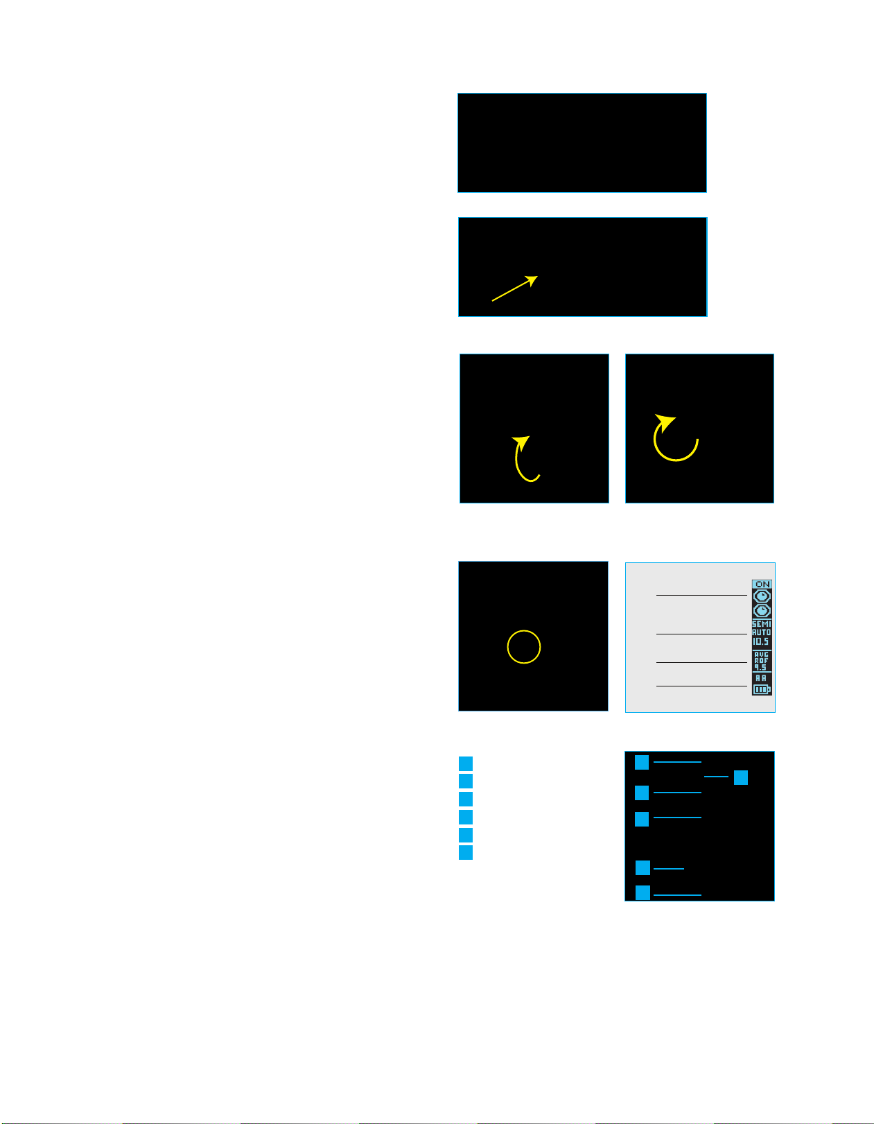
POWER MARKER ON/OFF - The Field One Force is an electronic
paintball marker powered by two AA batteries located in the moveable
Force Foregrip or a rechargeable battery located in the Force Grip
Frame. Batteries are included from the factory. Batteries should be
changed about every 50,000 shots or when the Battery Level
Indicator on the OLED screen reads LOW. If you notice a drop off in
the performance of your marker, changing to fresh batteries should
be one of the first measures you should take to resolve the issue.
Always use high quality batteries. Rechargeable AA batteries are not
recommended for the Force marker. Low cost zinc/carbon batteries
should be avoided. The battery compartment and any electronic
connectors or terminals should be kept dry and free from debris.
Make sure the battery door is secured in place after changing
batteries and that the batteries and battery door are oriented
correctly. To POWER ON your Force marker press the power button
located on the rear of the grip frame below the OLED
(fig 4A)
screen.
The OLED screen will illuminate displaying a brief “STARTUP
SCREEN.” After a moment, the HOME SCREEN will appear and give
you information about the FIRE MODE, Battery Life, 4C-ES Status,
ROF CAP and ROF of the last 10 shots
(fig 4B)
. The Force is ready
to shoot once you see the Home Screen. The electronic eyes will
default to EYES ON every time you POWER ON the marker. To
POWER OFF the marker- press and hold the power button for 4
seconds. A “...3..2..1..0..OFF” countdown will appear on the OLED
screen then the marker will shut down. When the OLED screen has
gone blank, the marker is OFF. It is still highly recommended that you
use a barrel blocking safety device even when you have the marker
powered OFF.
A
AB
C
D
E
F
Grip Frame
Bezel
OLED Screen
Power button
ASA
Cam Drive Knob
Grip Frame Rear View (fig 4C) (fig 4C)
(fig 2A)
(fig 2B)
(fig 3A)
(fig 4A) (fig 4B)
(fig 3B)
EYE INDICATOR
FIRE MODE INDICATOR
RATE OF FIRE INDICATOR
BATTERY LEVEL AND
SOURCE INDICATOR
A
AB
C
D
E
F
CAUTION: READ AND FOLLOW ALL SAFETY GUIDELINES AND WARNINGS BEFORE HANDLING OR
ATTEMPTING ANY WORK ON YOUR FIELD ONE PAINTBALL MARKER. SHOULD YOU BE UNSURE AT ANY
POINT, STOP AND GET HELP FROM A FIELD ONE PAINTBALL CERTIFIED TECHNICIAN.
LOAD UP - Attach your loader into the Lever Lock Feedneck by
opening the lever
(fig 5A)
. You may loosen the locking lever if
necessary by turning either the lever or the stainless steel thumb
screw
(fig 5B)
. Insert the loader into the feedneck and lock the lever
securing the loader in place
(fig 5C)
. The Lever Lock is designed to
hold the loader snug in the feedneck but should not be overtightened.
Overtightening the feedneck lever can cause damage to the feedneck
or loader neck. Once your loader is in the feedneck, adjust the thumb
screw to reach the desired level of tension. The Field One Force is
capable of high rates of fire. It is recommended that you use a high
performance motorized loader to get the most consistent rate of fire
and the highest possible performance from your Field One Force.
Make sure your barrel blocking safety device is in place before loading
your paintballs into the loader.
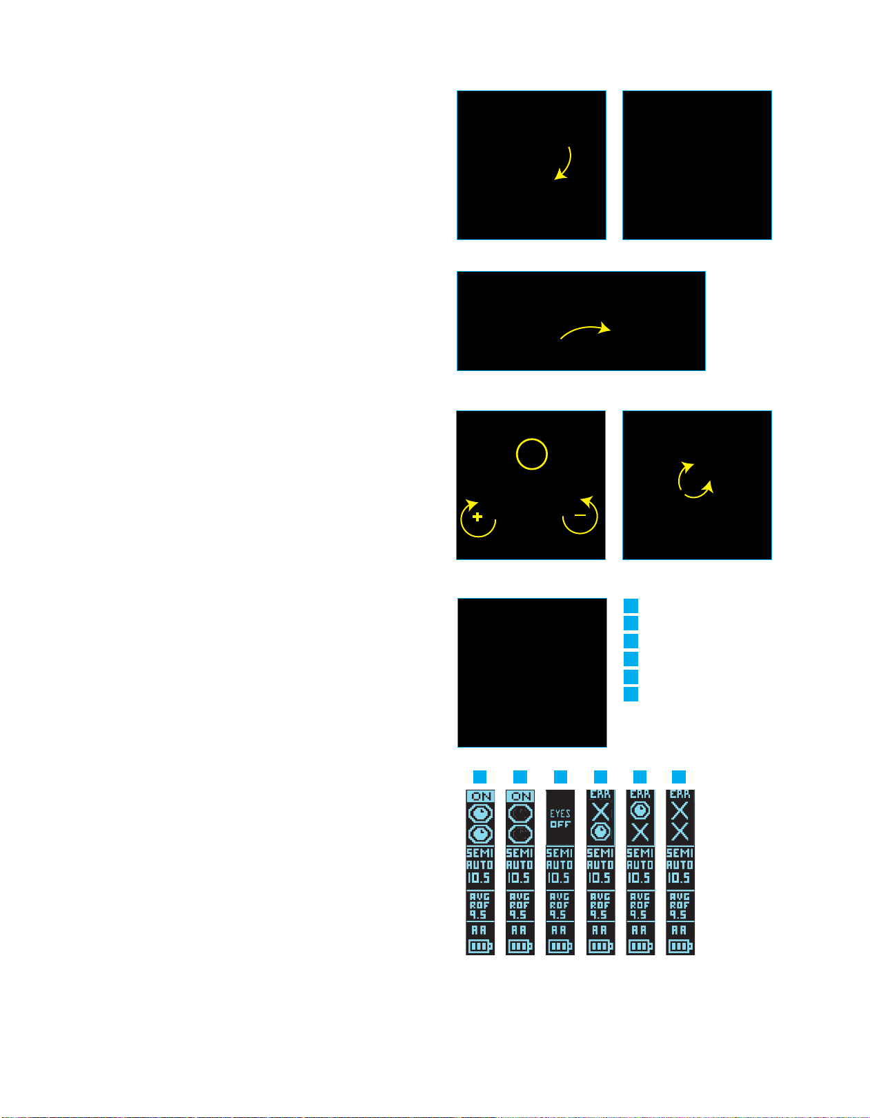
ADJUST YOUR VELOCITY - You must test your velocity at the start of
each paintball session or when you change paintball size or barrel
bore size. Make sure that your loader is filled with paintballs and
turned on. Whenever operating your marker, you must wear eye
protection specifically designed for paintball and compliant with ASTM
standards. Once in a safe area to fire your marker, remove the barrel
cover. Pull the trigger to fire the paintball marker over the chronograph
to measure the velocity. To adjust your velocity insert a ⅛ inch allen
wrench into the velocity adjustment screw
(fig 6A)
located on the
bottom of the Cam Drive ASA just forward of the Cam Drive ASA Knob
(fig 6B)
. To increase the velocity turn the screw clockwise
(facing you). To decrease the velocity turn the screw counter clockwise
(facing you). The range of adjustment is about 15 feet per second
(FPS) per quarter turn. Shoot 2 shots in between each adjustment to
stabilize the pressure. Only adjust the velocity adjustment screw by ¼
turn between chronograph measurements as this adjustment can be
sensitive. WARNING: DO NOT adjust the velocity of your Force
marker in excess of 300 FPS. Check with your local field or
tournament organization for the recommended maximum velocity
setting.
4C ILLUMINATE EYE SYSTEM (4C-ES) - Your Field One Force is
equipped with the 4C Illuminate Eye System consisting of 2 sets of
break-beam eyes (upper and lower)
(fig 7A)
, this feature allows the
Force to achieve maximum rates of fire without chopping paint. Even
with a high performance motorized loader, the Force needs proper eye
operation to avoid breaking/chopping paintballs in the breech. The eye
indicator located on the upper portion of the OLED HOME SCREEN
will display the status of the 4C-ES
(fig 7B)
. When your Force marker
is powered ON the 4C-ES system is active (ON) by default. When the
4C-ES is active and working properly the marker will not shoot unless
there is a ballt present in the breech (breaking the invisible beam
between the eyes). To turn the 4C-ES OFF tap the power button twice
within 1 second. You will notice that the OLED display indicates that
the 4C-ES status is OFF. You must turn off the 4C-ES in order to fire
your marker without paintballs (dry fire). It is not recommended that
you dry fire your marker excessively. To toggle between “EYES ON”
and “EYES OFF,” tap the power button twice within 1 second. Playing
with your 4C-ES “OFF” will greatly increase your chances of breaking
paint. If the eye indicator on your OLED screen shows that the eyes
are blocked/eye malfunction (ERROR), you may have to clean the
eyes to restore proper function.
A
AB
C
D
E
F
Eyes on Ball Loaded
Eyes on breach empty
Eyes off
Top eye fault (clean eyes)
Bottom eye fault
Both eyes fault (clean eyes)
Eye function HUD (fig 7B)
AAB C D E F
(fig 5A) (fig 5B)
(fig 5C)
(fig 6A)
+
(fig 6B)
-
(fig 7A)
(fig 7C)
+

CAUTION: READ AND FOLLOW ALL SAFETY GUIDELINES AND WARNINGS BEFORE HANDLING OR
ATTEMPTING ANY WORK ON YOUR FIELD ONE PAINTBALL MARKER. SHOULD YOU BE UNSURE AT ANY
POINT, STOP AND GET HELP FROM A FIELD ONE PAINTBALL CERTIFIED TECHNICIAN.
TOURNAMENT/BOARD LOCK - Your Force marker has a lock
function that insures that the settings cannot be adjusted without tools
when the lock is on. When the lock is ON, the lock indicator icon will
display if you attempt to enter “settings adjustment mode.” To turn the
lock OFF, turn on the marker and use your 5/64 allen wrench to
remove the 3 screws that hold the left grip panel to the grip frame
(fig 8A)
. Open the grip panel and press the button labeled “LOCK” on
the main board
(fig 8B)
. To toggle between Lock ON and OFF, repeat
these steps. When the marker is on and the LOCK button is pressed,
the OLED screen will display whether the board has been locked or
unlocked. Some tournaments will require you to play with the
tournament/board lock ON (settings are locked).
(fig 8A) (fig 8B)
PLAY!- Once you have followed and understood the steps listed above, you are now ready to take your
Field One Force out to play. HAVE FUN, BE SAFE AND SHOOT STRAIGHT!
• Be sure to adhere to all paintball safety guidelines and local rules/regulations
• If you have questions about safety or local regulations, contact your local paintball store or field
• Always wear paintball approved eye protection and face protection when operating your Field One Force
• Always use a barrel blocking safety device with your Field One Force whenever you are not operating
your marker
• Only shoot your paintball marker in areas where people, animals and property are not at risk of being
damaged or hurt by paintball projectiles
• Only shoot your paintball marker in areas where all people are wearing paintball approved eye and face
protection
CAUTION: READ AND FOLLOW ALL SAFETY GUIDELINES AND WARNINGS BEFORE HANDLING OR
ATTEMPTING ANY WORK ON YOUR FIELD ONE PAINTBALL MARKER. SHOULD YOU BE UNSURE AT ANY
POINT, STOP AND GET HELP FROM A FIELD ONE PAINTBALL CERTIFIED TECHNICIAN.
A
AB
Force Grip Frame
The Force grip frame houses the main board (Force Mainboard) for the Force, the OLED screen and Power Button, the HPR (Rhino
Regulator), velocity adjustment screw, trigger assembly and provides the mounting point for the Cam Drive ASA. Custom overmolded dual
durometer rubber grips protect the internals of the grip frame while providing the perfect amount of tactile function for the user to change
hands while operating and keep a firm grip when needed. The grip frame does not need to be removed during normal maintenance of the
Field One Force. Keeping the grip frame and the electronics within the grip frame free of moisture and debris is important and can be
maintained by removing both sides of the rubber grip panels. Access to the TOURNAMENT/BOARD LOCK button on the Force BLU18
Board can be had by removing the left-side grip panel. The Rhino Regulator can be accessed by removing the Cam Drive ASA from the
bottom of the grip frame.
C
Manifold Mounting Screws
Drive Manifold
Top Mainboard
Mounting Screws
Bottom Mainboard
Mounting Screw
Mainboard
C
AB
A
Bezel
OLED Screen
Power Button
PCB Board
1x3 Drive Manifold to Solenoid
1x4.5 Drive Manifold to Solenoid
PCB and Bezel Mounting Screws
Cam Drive ASA
Rhino Regulator
Downstream Bleed Valve
Gripframe
Front Gripframe to Body
Mounting Screw
1x3.5 Input
Manifold to Gripframe
1x3 DInput
Manifold to Solenoid
Input Manifold
KO Trigger
ASA Mounting Screws
Solenoid
Trigger Mounting Screw

CAUTION: READ AND FOLLOW ALL SAFETY GUIDELINES AND WARNINGS BEFORE HANDLING OR
ATTEMPTING ANY WORK ON YOUR FIELD ONE PAINTBALL MARKER. SHOULD YOU BE UNSURE AT ANY
POINT, STOP AND GET HELP FROM A FIELD ONE PAINTBALL CERTIFIED TECHNICIAN.
Force Electronics and OLED Screen
The electronics in the Field One Force serve as the “central nervous system” for the Force marker.
There are 5 board types in the Force
• Force Main Board
• Force Bridge Board (connects the eyes (4C-ES), batteries (power source and the Jumper Board)
• 4C-IS Boards (2)
• Force Jumper Board (allows the user to separate the body from the grip frame without disconnecting wires).
• Force Power Control and OLED Board
To eliminate the use of long wire harnesses and delicate wire harness connectors, the Force makes use of spring loaded pin connectors and
low profile ribbon connectors to keep power and communication going to and from the different electronic components of the marker. The
Force Mainboard comes equipped with a capacitor as a failsafe in case of temporary disconnect between the battery and the electronics in
the marker due to vibration or a hard impact with the ground. It is important to keep the Force and the electronic components in the Force
free from moisture, paint and debris. Never submerge the Force in water and always perform proper maintenance after using the Force in
wet conditions. Cleaning and drying the electronic components of the Force with a dry soft cloth and dry cotton swab will help to prolong
their life after using in wet conditions. If there is built up paint or dirt residue, you can use rubbing alcohol on a swab to clean electronics and
hard to reach cavities. Make sure electronic components and connectors are dry and clean before reassembly. Changing out wet batteries
and drying out the battery compartment will also help to prolong the life of the electronic components.
Battery Board
Battery Harness
Bridge Board
Left Eye
Jumper Harness
Jumper Board
Main Board
PCB Board
OLED Screen
Right Eye
Solenoid Connector
Solenoid
Tournament Lock Button
Microswitch
Power Select Switch LiPo Battery Connector
Speaker
LiPo Rechargeable Battery
LiPo Battery Connector
Power Button
AA Batteries
CAUTION: READ AND FOLLOW ALL SAFETY GUIDELINES AND WARNINGS BEFORE HANDLING OR
ATTEMPTING ANY WORK ON YOUR FIELD ONE PAINTBALL MARKER. SHOULD YOU BE UNSURE AT ANY
POINT, STOP AND GET HELP FROM A FIELD ONE PAINTBALL CERTIFIED TECHNICIAN.
Rhino Regulator
The Field One Force’s main air supply is regulated by the Rhino Regulator, which is mounted in the top of the ASA and housed within the
Force Grip Frame. Once you have connected an air source to the ASA, the air travels through the Rhino Regulator (and is regulated down to
about 145-155 psi) and directed to the solenoid and the Force Engine. The Force Rhino Regulator requires minimal maintenance and
should only be serviced if there is a decline in performance. Cleaning the piston, the reg seat and the reg housing and applying lube to all
regulator seals will help to keep the regulated air flow consistent.
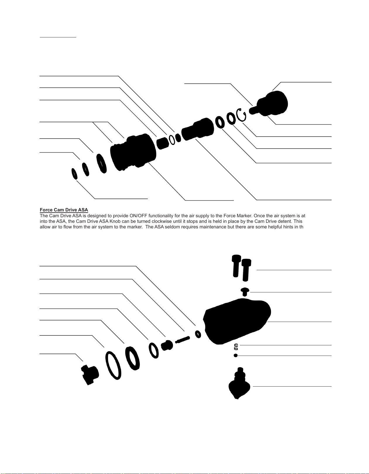
Force Cam Drive ASA
The Cam Drive ASA is designed to provide ON/OFF functionality for the air supply to the Force Marker. Once the air system is attached fully
into the ASA, the Cam Drive ASA Knob can be turned clockwise until it stops and is held in place by the Cam Drive detent. This action will
allow air to flow from the air system to the marker. The ASA seldom requires maintenance but there are some helpful hints in the
TROUBLESHOOTING section of this manual if you detect a leak coming from the ASA or ASA knob. Before attaching your air system to the
Cam Drive ASA, it is recommended that you clear any dirt or debris from the opening of the ASA, the ASA threads and the pin or ball valve
on your air system regulator. WARNING: Once you have turned your Cam Drive ASA to the OFF position and removed all paintballs from
your marker, take a clearing shot by holding down the trigger for one second to ensure there is no gas stored in the marker.
ASA Cam Drive Knob
Cam Detent Bearing
Cam Detent Spring
ASA Body
Cam Drive Knob Retaining Screw
ASA to Grip Frame Mounting Screws
005 ASA Main Seal
ASA Cam Activation Pin
Main Seal Support
011 ASA Outside Main Seal Retainer
ASA Filter
017 Outside ASA Filter
Main Seal Retainer
Reg Seat
Reg Adjuster
.237 OD Between Reg Seat and Reatiner
1x12 Outside Reg Adjuster Housing
12 U-Cup Inside Top Reg
Adjuster Housing
011 Inside Bottom Reg
Adjuster Housing
4.5x 1.5 90D Bottom Reg
Between Reg Adjuster and
ASA Reg Adjuster Reg Seat Retainer
008 Inside Reg Seat Housong
Under Washer and C- Clip
C-Clip
O-Ring Retaining Washer
Between O-ring and C-Clip
Spring Stack
Reg Piston 014 Top Reg Piston

CAUTION: READ AND FOLLOW ALL SAFETY GUIDELINES AND WARNINGS BEFORE HANDLING OR
ATTEMPTING ANY WORK ON YOUR FIELD ONE PAINTBALL MARKER. SHOULD YOU BE UNSURE AT ANY
POINT, STOP AND GET HELP FROM A FIELD ONE PAINTBALL CERTIFIED TECHNICIAN.
Force KO Trigger Assembly
The Force comes equipped with the KO magnetic trigger and offers a wide range of adjustability by using three different adjustments. To
adjust trigger pull length, use your 1/16th inch allen wrench and insert into the bottom hole in the KO trigger face. Turning the Trigger
Stopper Screw clockwise will shorten the trigger pull length. To adjust the activation point, use the same 1/16th inch allen wrench in the
middle hole in the trigger face. Turning the Trigger Activation Adjustment Screw clockwise will make the trigger activate earlier in the trigger
pull. Turning the screw counter clockwise will make the trigger activate later in the trigger pull. You can also adjust the trigger tension or
magnet tension behind the trigger by using your 1/16th inch allen wrench in the top hole in the KO trigger face and turning the Trigger
Tension Screw clockwise to get more resistance behind the trigger and counter clockwise to get less resistance behind the trigger pull. The
F1 factory trigger setting will keep close to equal trigger travel in front and behind the trigger activation point. This will help to avoid “runaway
trigger” or “trigger bounce.”
4C Illuminate Eye System, Eye Covers and Ball Detents
The eye system in the breech of the Field One Force is called the 4c IlluminateEye System. This system uses two sets of break beam eyes
to detect whether or not a paintball has settled in the breech and is ready to fire. The upper set of eyes communicates that a ball is moving
into the firing position so there is less delay required when the lower set of eyes reads that the paintball has arrived and allows the firing
sequence to take place. This combination of eyes and technology allows for the fastest read rate and produces incredibly high rates of fire
with the eyes fully functional. If a paintball cracks in the breech or is chopped by the bolt (shooting with eyes OFF) the eyes will need to be
cleaned to ensure that the “break beam” is unimpeded and the eyes are fully functional. To inspect or clean the eyes and ball detents, simply
remove the eye covers with your 5/64 allen wrench and wipe with a soft cloth or cotton swab until the eyes/eye boards/detents are free from
paint or debris. Do not use water to clean the eye boards as this may cause a short or malfunction in the eye board. Carefully place the eye
board back in the recessed area of the body and make sure the rubber ball detents are fully seated in the appropriate hole. When reattaching
the eye cover, make sure to not crush the eye board. The eye cover mounting screw should be snug but not overtightened. The eye cover
should sit flush with the body when properly installed. You can verify proper eye function by turning on the marker and checking the OLED
readout for eye function.
Trigger Mounting Screw
Trigger Spacer
Roller Bearings
Trigger Activation Adjustment Screw
Trigger Stopper Screw
A
A
Trigger Tension Adjustment Screw
Trigger Tension Magnet
KO Trigger
Eye Cover
Mounting Screw
Left Eye Cover
Ball Detent
Left 4-C Eye
Bridge Board
Ball Detent
Right Eye Cover
Eye Cover
Mounting Screw
Right 4-C Eye
Top Eye
Bottom Eye
CAUTION: READ AND FOLLOW ALL SAFETY GUIDELINES AND WARNINGS BEFORE HANDLING OR
ATTEMPTING ANY WORK ON YOUR FIELD ONE PAINTBALL MARKER. SHOULD YOU BE UNSURE AT ANY
POINT, STOP AND GET HELP FROM A FIELD ONE PAINTBALL CERTIFIED TECHNICIAN.
A
A
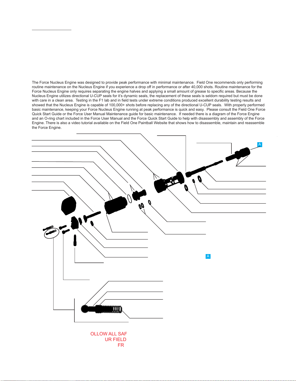
Force Nucleus Engine
The Force Nucleus Engine is a Spool Valve type engine that works by moving air from the volume chamber through the bolt tip to propel the
paintball through the barrel at consistent velocities. With each shot cycle, the Force solenoid provides a measured amount of air to the
engine, moving the ram and bolt forward and back to open and close the different chambers of the Force Nucleus Engine. The Nucleus
Engine is made up of 7 main components:
• Bolt Tip
• Ram Shaft
•Reduction Shaft
• Volume Chamber
•Brass Shut Off
• Ram Housing
• Back Block and Back Cap Assembly
The Force Nucleus Engine was designed to provide peak performance with minimal maintenance. Field One recommends only performing
routine maintenance on the Nucleus Engine if you experience a drop off in performance or after 40,000 shots. Routine maintenance for the
Force Nucleus Engine only requires separating the engine halves and applying a small amount of grease to specific areas. Because the
Nucleus Engine utilizes directional U-CUP seals for it’s dynamic seals, the replacement of these seals is seldom required but must be done
with care in a clean area. Testing in the F1 lab and in field tests under extreme conditions produced excellent durability testing results and
showed that the Nucleus Engine is capable of 100,000+ shots before replacing any of the directional U-CUP seals. With properly performed
basic maintenance, keeping your Force Nucleus Engine running at peak performance is quick and easy. Please consult the Field One Force
Quick Start Guide or the Force User Manual Maintenance guide for basic maintenance. If needed there is a diagram of the Force Engine
and an O-ring chart included in the Force User Manual and the Force Quick Start Guide to help with disassembly and assembly of the Force
Engine. There is also a video tutorial available on the Field One Paintball Website that shows how to disassemble, maintain and reassemble
the Force Engine.
Magnetic Back Cap Detaining Ball
Gas Interlock Magnet Post
Gas Interlock Piston
Gas Interlock Spring
Gas Interlock Assembly
Back Cap
Pillow Tip Insert
Back Block Screw
Back Block Pin
Back Block
Reduction Shaft Support Pad
Retraction Bumper (on reduction shaft)
1x2 between Ram Housing
and Reduction Shaft
Reduction Shaft
Ram Housing
021 Outside Ram Housing
1x15 between Ram Housing and
Volume Chamber
017 Inside Volume Chamber
Brass Shut O
021 Outside Volume Chamber
020 Outside Volume Chamber front 011 U Cup Outside Ram (opening faces front)
Bolt
015 outside
Bolt
Ram
Extension Bumper (on Ram)
009 U Cup inside Ram (opening faces front)
110 U Cup inside Volume Chamber front
(opening faces back)
Volume Chamber
011 inside Brass Shut Off front
011 U Cup inside Brass Shut Off rear
(openings face away from each other)

CAUTION: READ AND FOLLOW ALL SAFETY GUIDELINES AND WARNINGS BEFORE HANDLING OR
ATTEMPTING ANY WORK ON YOUR FIELD ONE PAINTBALL MARKER. SHOULD YOU BE UNSURE AT ANY
POINT, STOP AND GET HELP FROM A FIELD ONE PAINTBALL CERTIFIED TECHNICIAN.
A
AB AB
LeverLock Feedneck
The Field One Force comes equipped with the new LeverLock clamping feedneck. This feedneck is adjustable without tools and allows for
the use of a variety of different motorized loaders and ensures a snug fit. Do not overtighten the clamping lever screw as this may cause
damage to the feedneck or the clamping lever bolt. If the lever ever becomes too tight to manipulate with your fingers, you can use a 1/8th
inch allen wrench to loosen the LeverLock assembly.
Force GRIP SHIFT (Dual Position) Foregrip (Battery Compartment)
The Force Foregrip is designed to provide 2 different mounting points so the user can choose the foregrip stance or distance that is most
comfortable for their playing style. The Force Foregrip position change involves separating the foregrip (also the AA(2) battery compartment)
from the reversal plate and then switching the orientation of the Force Foregrip Reversal Plate before reinstalling the foregrip. This
adjustment operation is not meant to be performed while playing or operating the marker. It is highly recommended that this adjustment
operation is done where there is a clean flat surface to work with and all of the separate components of the marker are removed (REMOVE
loader, tank, barrel). The foregrip (battery compartment) will remain connected to the marker with the power supply wire harness. Excessive
pressure or tension on this wire harness while changing foregrip positions will cause power failure or damage the electronic components in
the marker. Please refer to the Grip Shift instructions or the Grip Shift Video Tutorial before starting this process
A
A
Reversal Plate Mounting Screws
Reversal Plate
Foregrip Housing
Foregrip Mounting Screws
Battery Board
Foregrip Core
AA Batteries
Battery Door
Feedneck
Cam Pivot
Lever
Adjuster Nut
Adjuster Knob
Locking Screw
Adjuster Bolt

CAUTION: READ AND FOLLOW ALL SAFETY GUIDELINES AND WARNINGS BEFORE HANDLING OR
ATTEMPTING ANY WORK ON YOUR FIELD ONE PAINTBALL MARKER. SHOULD YOU BE UNSURE AT ANY
POINT, STOP AND GET HELP FROM A FIELD ONE PAINTBALL CERTIFIED TECHNICIAN.
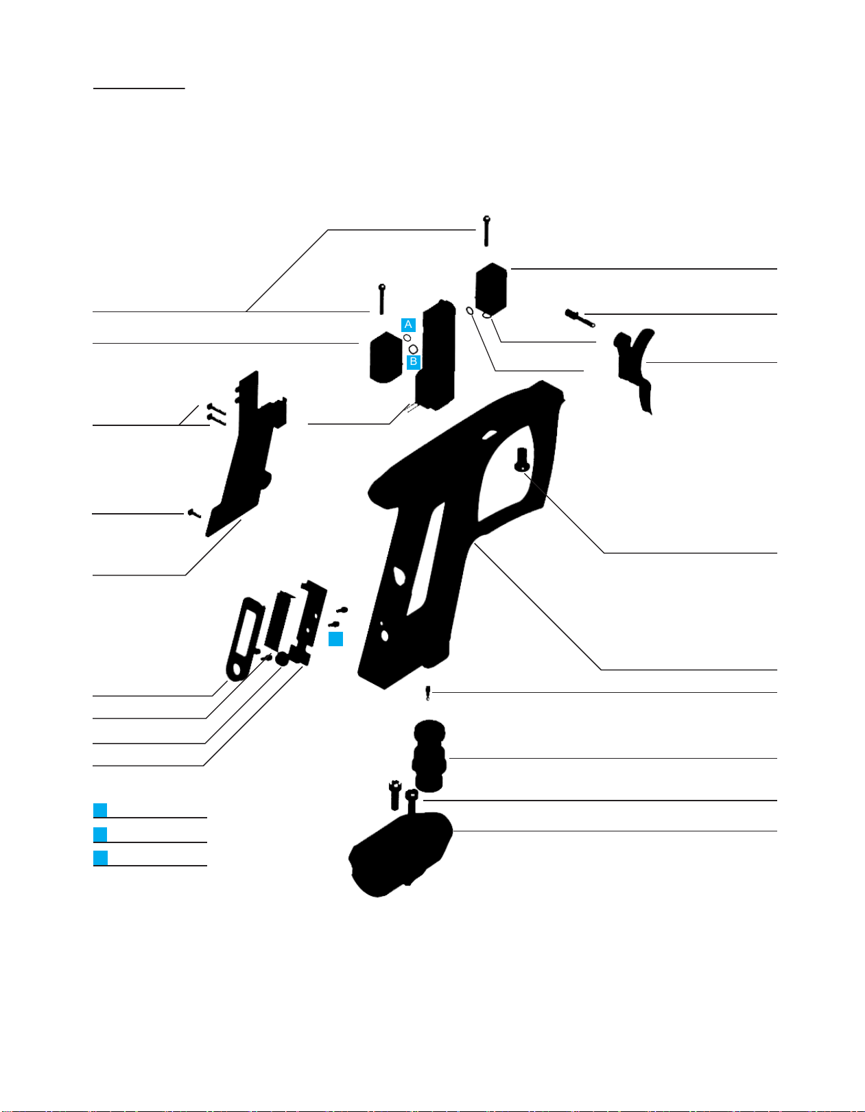
Force Body
The Force Body is the shell that holds the Force together. There are only three o-rings in the force body that seal between both manifolds
and the underside of the body. The Jumper board screws into the mainbody and connects to the main board by way of pressure contact
pads. The Jumper harness connects the jumper board to the Bridge Board which relays information to and from the eyes and power from the
AA batteries in the foregrip to the mainboard. The Force Bridge holds the Bridge Board in place and creates a mounting point for the
gripframe.
A
Rear Gripframe Mounting Screw (insert from inside the body)
A
Leverlock Feedneck
Eye Cover
Mainbody
005 Mainbody to Drive
Manifold
007 Mainbody to Input
Manifold
Jumper Harness
Bridge
Bridge Board (under Bridge)
Battery Harness
Jumper Board

CAUTION: READ AND FOLLOW ALL SAFETY GUIDELINES AND WARNINGS BEFORE HANDLING OR
ATTEMPTING ANY WORK ON YOUR FIELD ONE PAINTBALL MARKER. SHOULD YOU BE UNSURE AT ANY
POINT, STOP AND GET HELP FROM A FIELD ONE PAINTBALL CERTIFIED TECHNICIAN.
Adjusting your FORCE Software Settings (Force Main Board Version 1.0)
The Field One Force comes equipped with the Force Main Board. The Force Main Board allows the user to manually adjust board settings
with the OLED interface on the Force grip frame.
Your Field One Force will come from the Field One Paintball Factory with the latest program code and the optimal board settings (referred to
as “DEFAULT” or “FACTORY DEFAULT”) for the highest marker performance under most conditions. Once board settings have been
changed, board settings can be adjusted back to “FACTORY DEFAULT” at anytime by activating “Factory Reset” in PROGRAMMING
MODE. Depending on local rules and regulations you may need to adjust the RATE OF FIRE setting and/or the FIRING MODE setting for
your Force Marker before playing with your Force Marker. Instructions for adjusting these settings can be found here in the Field One Force
User Manual or the Field One Force Quick Start Guide.
TOURNAMENT/BOARD LOCK
Your Force marker has a lock function that insures that the programmable settings cannot be adjusted without tools when the lock is ON.
When the lock is ON, the lock indicator icon will display if you attempt to enter “settings adjustment mode." To turn the lock OFF, turn on the
marker and use your 5/64 allen wrench to remove the 3 screws that hold the left grip panel to the grip frame. Open the grip panel and press
the button labeled “LOCK” on the main board. To toggle between Lock ON and OFF, repeat these steps. When the marker is on and the
LOCK button is pressed, the OLED screen will display whether the board has been locked or unlocked. Some tournaments will require you
to play with the tournament/board lock ON (settings are locked).
Once the tournament/board lock is off you may adjust the software settings by using the grip frame OLED. The marker will not fire while in
programming mode but we highly suggest you remove the air source and paintballs from the marker before entering PROGRAMMING
MODE and adjusting settings. WARNING: Always keep barrel blocking device in place while adjusting board settings.
Using the OLED to Adjust Settings
To access the settings menu
1 Hold down the trigger while powering the marker ON. The OLED screen will flash with the current software version and then enter
PROGRAMMING MODE.
2 Once in PROGRAMMING MODE, you can cycle through the settings by pulling the trigger until you reach the desired setting. (By
scrolling through the different settings, you will also be able to see the current value for each setting.)
3 To adjust a setting scroll to the desired setting by pulling the trigger then tap the power button to enter ADJUSTMENT MODE for that
particular setting.
4 Use the trigger to adjust the setting to your satisfaction.
5 Tap the power button once more to exit the ADJUSTMENT MODE for that setting. The setting has now been changed.
6 If you wish to return to the factory settings (DEFAULT), enter programming mode, scroll to the FACTORY RESET setting and adjust
to “RESET YES.”
You may adjust more settings while you are in PROGRAMMING MODE by following steps 3 through 5 listed above turn the marker OFF by
pressing and holding the power button for 3 seconds to save your new settings. The gun will retain the new settings until they are changed or
the software is updated. Below is a list of adjustable settings and their functionality.

CAUTION: READ AND FOLLOW ALL SAFETY GUIDELINES AND WARNINGS BEFORE HANDLING OR
ATTEMPTING ANY WORK ON YOUR FIELD ONE PAINTBALL MARKER. SHOULD YOU BE UNSURE AT ANY
POINT, STOP AND GET HELP FROM A FIELD ONE PAINTBALL CERTIFIED TECHNICIAN.
Force Board - Adjustable Settings Explained
FIRE MODE - This setting determines the type of FIRE MODE your Force will use. The Maximum Rate of Fire and the Rate of Fire Cap
will be determined by the ROF CAP setting.
Modes Available:
•NXL Ramp - (World Paintball League current ramping rules). This fire mode is specific to the type of ramp and ramp settings
allowed by the NXL. The ROF Cap will have to be set separately once the FIRE MODE is set to “NXL Ramp."
•Custom Ramp - Adjustable ramp settings. This is the only fire mode that will allow
adjustability of the three ramp settings (RAMP START, RAMP KICK IN ROF, and RAMP
SUSTAIN ROF)
• Semi-Auto - one shot cycle per trigger pull
• 3 Shot Burst - 3 shot cycles per trigger pull (single shot before 3 shot burst engages)
• Full Auto - holding the trigger down will cycle the marker (single shot before full auto engages)
From the NXL Rulebook.
RATE OF FIRE (ROF) CAP - This setting will determine the limit on RATE OF FIRE. This setting will not override the FIRE MODE setting if
using an uncapped FIRE MODE. UNCAPPED RATE OF FIRE will allow the Force to shoot as fast as the marker will mechanically cycle
(EYES OFF) or as fast as the loader can feed paintballs to the marker (EYES ON).
Range of Adjustment: 2 BPS - 20 BPS
Default: 10.5 BPS (NXL)
EYES OFF RATE OF FIRE (ROF OFF) - This setting allows the user to set a separate RATE OF FIRE CAP if the eyes are toggled to “eyes
OFF” or if there is an eye malfunction.
PRO TIP for EYES OFF ROF setting: Setting the EYES OFF RATE OF FIRE lower than RATE OF FIRE CAP is recommended to reduce
paintball breakage in the event the eyes become dirty or disabled. 8 BPS is a good default setting in case the eyes are no longer functioning
and you must continue to play before addressing the issue.
Range of Adjustment: 2 BPS - 25 BPS- UNCAPPED
Default: 8.5 BPS

DWELL - The amount of time the solenoid is energized each time the marker is fired. Too low of a dwell setting may lead to inconsistency or
drop off. Too high of a dwell can cause bad air efficiency.
Default: 16
BALL IN PLACE (BIP) DELAY - This setting is referred to as the “bounce detector” setting and is designed to help prevent chopping in the
breech as the last paintballs in the loader “bounce” in the breech. PRO TIP for BIP DELAY setting: If you commonly break or chop the last ball
or two in your loader, raise your BD DELAY setting higher than the factory DEFAULT setting.
Default: MID HI
EYE POWER - The Eye Power setting adjusts the intensity of the eye beam. The higher the setting is set the more resistance the eye puts on
the beam. If your marker reads that there is a ball in the breach but will not fire you should increase this setting.
Default: Mid Lo
DEBOUNCE - This setting controls the read-rate of your trigger pull and can be thought of as trigger bounce sensitivity. Lowering your
D-BOUNCE setting can result in higher rates of fire (trigger/micro-switch bouncing), especially in SEMI-AUTO/UNCAPPED fire mode. Raising
your D-BOUNCE setting can help to eliminate “runaway trigger” or excessive “trigger/micro-switch bouncing”
Range of Adjustment:
Default: 2
RAMP START - The number of trigger pulls required to start ramping.
RAMP KICK IN (ROF) - The rate of fire that must be achieved to begin ramping.
RAMP SUSTAIN (ROF) - The rate of fire needed to sustain ramping.
ANTI BOLT STICK (ABS) - This setting will increase the dwell setting when the gun is left for a certain amount of time (adjustable in “ABS
time”. This setting should be set at a higher dwell time than the current dwell setting. If you experience first shot drop off and basic engine
maintenance does not fix it try increasing this setting. This setting will not affect the velocity.
Default:4
ANTI BOLT STICK (ABS Time) - This setting controls the amount of time the gun can rest before the ABS Dwell kicks in.
Default: 30 seconds
Chirp- This setting controls weather the speaker is ON or OFF.
Default: ON
CHIRP - This setting controls whether the speaker is ON or OFF.
Default: ON
SHOT COUNTER - This keeps track of the amount of shots the gun has fired with or without paint. You can reset the counter by selecting it in
the settings menu.
GAME TIMER - The Field One Force comes with a game timer built into the Force BLU18 board. The user will be able to set the timer to a
specified amount of time and then start the timer with a trigger pull at the beginning of a game or match. To access the TIMER SCREEN
before a game or match, press and hold the power button for 1.5 seconds. Once TIMER SCREEN is displayed on the OLED screen, you can
start the timer by pulling the trigger once. Once the timer has been started, the time remaining will be displayed on the OLED screen on the
grip frame. To reset the GAME TIMER, press and hold the power button for 1.5 seconds. This will also return you to the HOME screen.
TEXT ORIENTATION - This setting will allow right-handed and left-handed users to switch the orientation of the OLED text to best suit how
they like to hold the gun while adjusting settings.
Default: Right Hand text
FACTORY RESET - This will restore the Field One Factory settings.
CAUTION: READ AND FOLLOW ALL SAFETY GUIDELINES AND WARNINGS BEFORE HANDLING OR
ATTEMPTING ANY WORK ON YOUR FIELD ONE PAINTBALL MARKER. SHOULD YOU BE UNSURE AT ANY
POINT, STOP AND GET HELP FROM A FIELD ONE PAINTBALL CERTIFIED TECHNICIAN.

CAUTION: READ AND FOLLOW ALL SAFETY GUIDELINES AND WARNINGS BEFORE HANDLING OR
ATTEMPTING ANY WORK ON YOUR FIELD ONE PAINTBALL MARKER. SHOULD YOU BE UNSURE AT ANY
POINT, STOP AND GET HELP FROM A FIELD ONE PAINTBALL CERTIFIED TECHNICIAN.
F1 Force Maintenance
Your Field One Force marker was designed to require minimal maintenance. However, to keep the Force working at the highest performance
level, it is recommended that a regular maintenance schedule be kept. In this section, we will discuss the tools needed to maintain the Force
marker and layout a maintenance schedule that will help to keep the Force working at it’s best.
Tools needed to perform regular maintenance on the Force:
• Standard Allen Wrench set.
• Maintenance Kit included with the Field One Force (7/32, 1/8, 5/64, 1/16 Standard Allen Wrenches).
• Field One approved marker lube (comes with your Force Marker).
• Barrel cleaning squeegee.
• Spare O-ring Kit (comes in the Force Maintenance Kit).
• AA Batteries or Force Rechargeable Battery Charger.
• These items are also helpful for performing routine maintenance:
○Small Soft bristle brush (for cleaning small spaces and electronics.
○Cotton swabs (for applying grease to engine and regulator components).
○Long “T Handle” 1/8th allen wrench (for adjusting the position of the Force GRIP SHIFT adjustable foregrip).
○Vice Grips with soft jaws (to separate Bolt from Ram if they get overtightened).
Field One Force Maintenance Schedule:
This schedule is designed to prevent failure during play and promote peak level performance. As with any paintball marker,
maintenance works on an “as needed” basis but is best performed on a “preventive schedule." Maintenance involving cleaning the
eyes, breech and barrel will be required any time you break paintballs in that area and it is hindering the performance of the marker.
•Before you play Check/clean barrel and breech area. Make sure the ASA is clean from debris/dirt/moisture before attaching your
air system. Chrono your marker. Check/change/charge battery if battery meter is showing “LOW.”
•”Once Month/ Before Event (Approximately 40K shots from last routine maintenance)- clean and inspect eyes and detents- replace
detents if they look heavily worn, perform routine engine maintenance if there is a decline in performance (See “Engine Quick Start
Guide” or Page (X) of the Force User Manual).
•Once a year/ Season rebuild engine o-rings and seals only if there is a decline in performance, rebuild regulator o-rings only if
there is a decline in performance.
•Before you put your marker away after playing wipe off external surfaces of your marker to prevent corrosion/damage. Check
and clean breech area. Ensure there is no more pressure stored in the marker. Turn marker off. Store in a clean and dry area.
Avoid storing your marker in extreme temperatures to avoid damage to the electronic components and seals.
Please visit Fieldonepainball.com and the Filed One Paintball YouTube Channel for more information on tech tips and maintenance.
CAUTION: READ AND FOLLOW ALL SAFETY GUIDELINES AND WARNINGS BEFORE HANDLING OR ATTEMPTING ANY WORK ON
YOUR FIELD ONE PAINTBALL MARKER. SHOULD YOU BE UNSURE AT ANY POINT, STOP AND GET HELP FROM A FIELD ONE
PAINTBALL CERTIFIED TECHNICIAN.
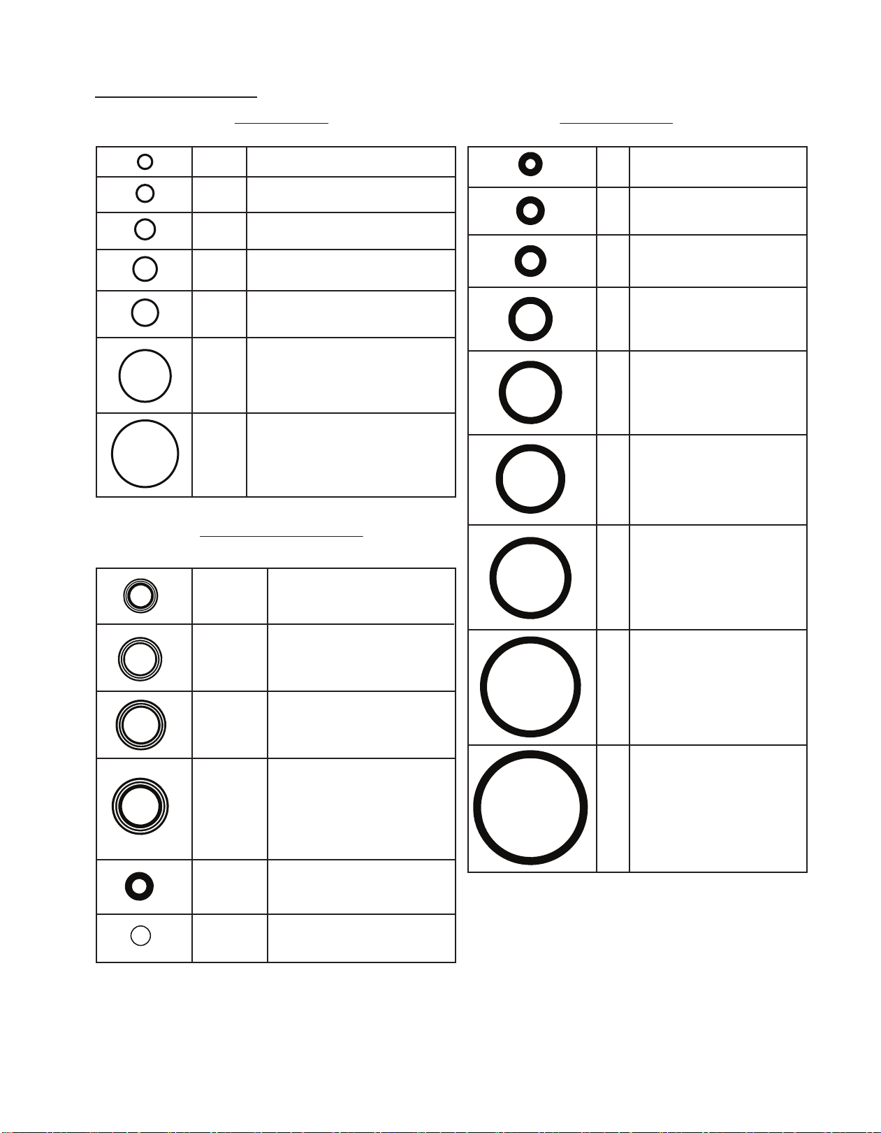
O-ring Size Chart.
x1 inside ram shaft
U- CUP 011
x1 Inside front of Volume
Chamber (opening faces rear)
011
1x12
1x15
1x2 005
007
1x3
1x3.5
1x4.5
1x5
008
014
015
021
020
017
x1 Outside front
Volume Chamber
x3 Outside rear
Voulme Chamber
x2 Outside ram housing
4.5x1.5 90D
x1 Ram Housing rear to reducton shaft
x1 Input Manifold, x1 Drive
Manifold, x2 Interlock Plungers
O-ring Size Location(s)
O-ring Size Location(s)
O-ring Size Location(s)
METRIC O-RINGS
U-CUPs and CUSTOM ORINGS
STANDARD O-RINGS
x1 Gripframe to bottom Input
manifold
x1 Drive Manifold to Solenoid
x1 Spring Stack Retainer
x2 Outside Rhino Reg
Adjuster Housing
x2 Body botttom to Drive Manifold
x1 ASA Main Seal Retainer
x1Body botttom to Input
Manifold
x1 inside Reg Seat Housing
under C-clip and washer
x1 inside bottom Rhino Reg
Adjuster Housing
x1 Inside front Brass Shut Off
x1 ASA Outside Mainseal Retainer
x1 Outside Rhino Reg Piston
x2 Bolt Tip
x2 inside rear Volume
Chamber to Brass Shut Off
x1 ASA Filter
U- CUP 009
1x outside ram shaft
2x Inside shut off
U- CUP 110
x1 bottom Rhino Reg between
reg Adjuster and ASA
x1 Ram Housing between
engine halves.
U- CUP 012 x1 Inside top Rhino Reg Adjuster
Hosing. (opening faces down)
.237 OD
Rhino Reg Seat
Retainer (between reg
seat and Reg Seat Retainer)
Table of contents


