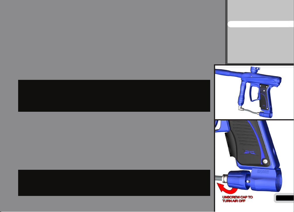
Installing a Preset Air System
Your MacDev Droid comes equipped with a high quality venting ASA (Air Sys-
tem Adaptor) that is designed for use with commercially available Air/Nitrogen
systems.
The venting ASA that is included with your Droid uses a screw cap to turn the
air from your preset system on or off. Before installing your preset air system,
you must unscrew the ASA cap by approximately 3 turns (do not unscrew it
further, as the cap can come off completely).
Once this is done, carefully screw your air system into the ASA until it stops.
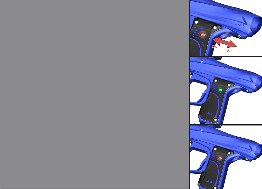
Turning the air on and off
To pressurise your Droid marker, screw the ASA cap down until it stops. This
will depress the pin on the end of your air system and pressurise the marker
(provided you have sufcient air in your air system).
WHEN SCREWING YOUR AIR SYSTEM INTO THE ASA, THE
THREADS SHOULD BE LOOSE. IF AT ANY POINT THEY BECOME
TIGHT, DO NOT FORCE THE THREADS, THIS MAY CAUSE DAMAGE
TO YOUR SYSTEM OR YOUR DROID MARKER!
NOTE: WHEN YOU UNSCREW THE ASA CAP, YOUR MARKER USU-
ALLY STORES ONE SHOT. POINT THE MARKER IN A SAFE DIREC-
TION AND FIRE OFF THAT SHOT BEFORE ENTERING A SAFE AREA.
8
Contents
Know your Droid
Quick Setup
Using your Droid
Advanced Setup
Maintenance
Parts List
Troubleshooting