Bob Long Technologies MARQUEE Series User manual

evolution redefined.
www.boblongdirect.com

Section Page
Safety . . . . . . . . . . . . . . . . . . . . . . . . . . . . . . . . . . . . . . . . . . . . . . . . . . . . . . . . . . . . . . . . . . . . . . . . . . . . .2
Warranty . . . . . . . . . . . . . . . . . . . . . . . . . . . . . . . . . . . . . . . . . . . . . . . . . . . . . . . . . . . . . . . . . . . . . . . . . . .3
History (theory of operation). . . . . . . . . . . . . . . . . . . . . . . . . . . . . . . . . . . . . . . . . . . . . . . . . . . . . . . . . . .3
General Description . . . . . . . . . . . . . . . . . . . . . . . . . . . . . . . . . . . . . . . . . . . . . . . . . . . . . . . . . . . . . . . . . .3
Introduction . . . . . . . . . . . . . . . . . . . . . . . . . . . . . . . . . . . . . . . . . . . . . . . . . . . . . . . . . . . . . . . . . . . . . . . . .4
Ammunition Aspects . . . . . . . . . . . . . . . . . . . . . . . . . . . . . . . . . . . . . . . . . . . . . . . . . . . . . . . . . . . . . . . . .5
Hopper . . . . . . . . . . . . . . . . . . . . . . . . . . . . . . . . . . . . . . . . . . . . . . . . . . . . . . . . . . . . . . . . . . . . . . . . . . .5
Paint . . . . . . . . . . . . . . . . . . . . . . . . . . . . . . . . . . . . . . . . . . . . . . . . . . . . . . . . . . . . . . . . . . . . . . . . . . . . .5
Operation . . . . . . . . . . . . . . . . . . . . . . . . . . . . . . . . . . . . . . . . . . . . . . . . . . . . . . . . . . . . . . . . . . . . . . . . . . .6
Gas Configurations . . . . . . . . . . . . . . . . . . . . . . . . . . . . . . . . . . . . . . . . . . . . . . . . . . . . . . . . . . . . . . . . .6
Electronics . . . . . . . . . . . . . . . . . . . . . . . . . . . . . . . . . . . . . . . . . . . . . . . . . . . . . . . . . . . . . . . . . . . . . . . . .7
Battery Information . . . . . . . . . . . . . . . . . . . . . . . . . . . . . . . . . . . . . . . . . . . . . . . . . . . . . . . . . . . . . . . . .7
Anti-Chop Eyes . . . . . . . . . . . . . . . . . . . . . . . . . . . . . . . . . . . . . . . . . . . . . . . . . . . . . . . . . . . . . . . . . . . .7
Factory Settings . . . . . . . . . . . . . . . . . . . . . . . . . . . . . . . . . . . . . . . . . . . . . . . . . . . . . . . . . . . . . . . . . . . .7
Board Operation . . . . . . . . . . . . . . . . . . . . . . . . . . . . . . . . . . . . . . . . . . . . . . . . . . . . . . . . . . . . . . . . . . . .8
Powering Up . . . . . . . . . . . . . . . . . . . . . . . . . . . . . . . . . . . . . . . . . . . . . . . . . . . . . . . . . . . . . . . . . . . . . .8
LCD Screen . . . . . . . . . . . . . . . . . . . . . . . . . . . . . . . . . . . . . . . . . . . . . . . . . . . . . . . . . . . . . . . . . . . . . . .8
Modes of Operation . . . . . . . . . . . . . . . . . . . . . . . . . . . . . . . . . . . . . . . . . . . . . . . . . . . . . . . . . . . . . . . . .8
Mode Selection & Competition Modes (All Leagues). . . . . . . . . . . . . . . . . . . . . . . . . . . . . . . . . . . . . . . .9
Competition Lock . . . . . . . . . . . . . . . . . . . . . . . . . . . . . . . . . . . . . . . . . . . . . . . . . . . . . . . . . . . . . . . . . 11
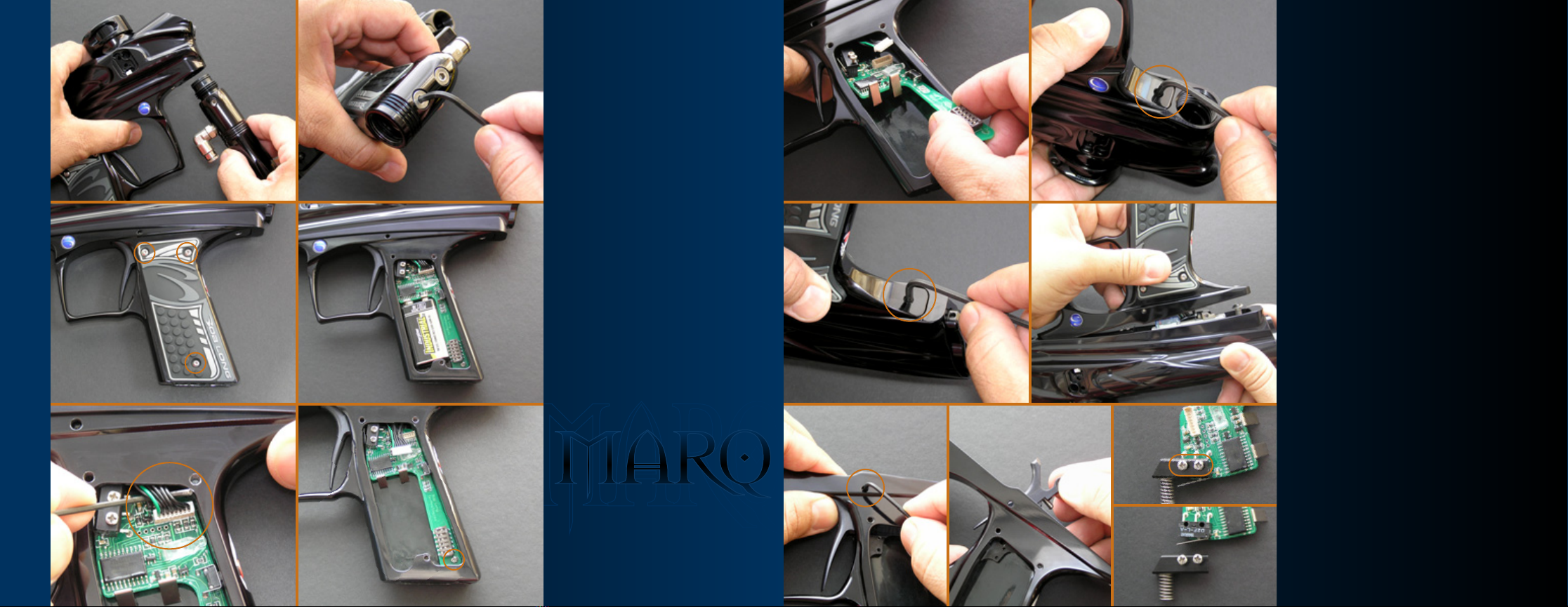
Assembly & Disassembly . . . . . . . . . . . . . . . . . . . . . . . . . . . . . . . . . . . . . . . . . . . . . . . . . . . . . . . . . . . . .13
Trigger Frame Disassembly . . . . . . . . . . . . . . . . . . . . . . . . . . . . . . . . . . . . . . . . . . . . . . . . . . . . . . . . . .13
Regulator Disassembly . . . . . . . . . . . . . . . . . . . . . . . . . . . . . . . . . . . . . . . . . . . . . . . . . . . . . . . . . . . . .15
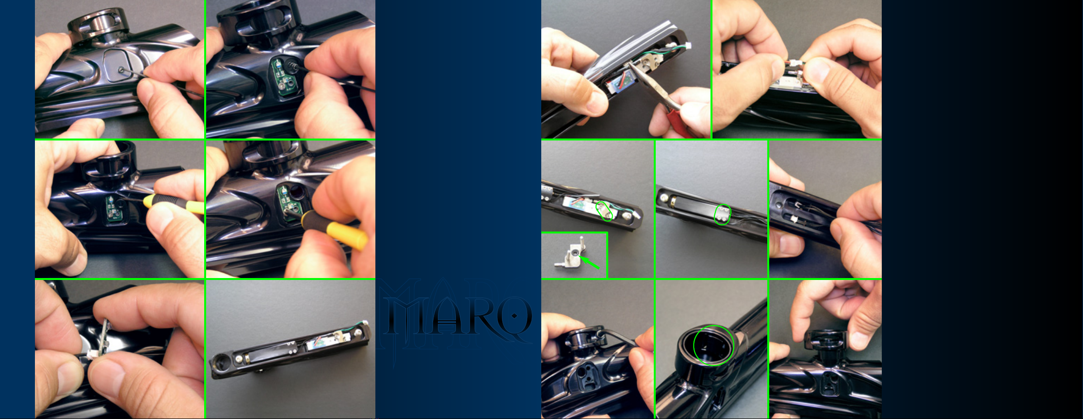
Body Disassembly . . . . . . . . . . . . . . . . . . . . . . . . . . . . . . . . . . . . . . . . . . . . . . . . . . . . . . . . . . . . . . . . .17
Assembly Tips . . . . . . . . . . . . . . . . . . . . . . . . . . . . . . . . . . . . . . . . . . . . . . . . . . . . . . . . . . . . . . . . . . . .19
General Maintenance . . . . . . . . . . . . . . . . . . . . . . . . . . . . . . . . . . . . . . . . . . . . . . . . . . . . . . . . . . . . . . .20
Consumables . . . . . . . . . . . . . . . . . . . . . . . . . . . . . . . . . . . . . . . . . . . . . . . . . . . . . . . . . . . . . . . . . . . . .20
Troubleshooting . . . . . . . . . . . . . . . . . . . . . . . . . . . . . . . . . . . . . . . . . . . . . . . . . . . . . . . . . . . . . . . . . . . .21
Technical Specifications . . . . . . . . . . . . . . . . . . . . . . . . . . . . . . . . . . . . . . . . . . . . . . . . . . . . . . . . . . . . .23
O-ring Specifications/Identification . . . . . . . . . . . . . . . . . . . . . . . . . . . . . . . . . . . . . . . . . . . . . . . . . .23
Screw Specifications/Identification . . . . . . . . . . . . . . . . . . . . . . . . . . . . . . . . . . . . . . . . . . . . . . . . . . .25
Complete Parts List . . . . . . . . . . . . . . . . . . . . . . . . . . . . . . . . . . . . . . . . . . . . . . . . . . . . . . . . . . . . . . . . .27
table of contents
12
welcome
CongratulationsonyourpurchaseoftheMARQSeriesPaintballMarker.TheMARQrepresentsthelatest
in Paintball Marker technology at an affordable price. Before operating your MARQ, Please read the
entire Manual thoroughly.
!WARNING!
This Paintball Marker is not a toy. Misuse or mishandling can result in serious injury or death. Every person
within range of a loaded Paintball Marker must wear eye protection specifically designed for Paintball.
Recommended at least 18 years of age to purchase, 14 years old to use with adult supervision or 10 years old
to use on Paintball fields meeting ASTM standards F1777-97. Be sure to read the entire instruction manual
before operating your MARQ.
SAFETY
Please follow all local, state, and federal laws concerning the operation and use of Paintball Markers.
By purchasing this Paintball Marker “YOU” assume all liability. B.L.A.S.T. assumes no liability for injury
or death due to misuse or mishandling of this Marker.
CAUTION
Never point a Paintball Marker at anyone not wearing Paintball-Approved goggles. Even at the lowest
possible operating velocity, a Paintball will cause serious injury should it hit someone in the eye area.
Never under any circumstances look down the barrel of your Marker. Even if wearing Paintball approved
goggles, you should Never look down the barrel of any Paintball Marker.
Before performing any maintenance on the Marker, ensure air source is disconnected and Marker has been
degassed. Always ensure Marker is OFF whenever Marker is not operational.
Always insert barrel plug in barrel when Marker is not operational. Remove barrel plug only in designated
operational areas.
Only play at commercial playing fields that have a chronograph, referees, and clearly marked safe areas.
Chronograph your Marker before each game to ensure Marker is operating at a safe velocity. Safe velocity
is considered to be 280 feet per second (fps).

INTRODUCTION
The MARQ Series Paintball Marker is controlled via the single-button rubber on/off membrane located on the rear
of the Trigger Frame. All of the functions of the MARQ can be easily accessed and changed via the dip switch
panel located on the front side of the board.
GettingStarted
To power up your MARQ, Press the ON/OFF button. To turn off your MARQ, press and hold ON/OFF button for
approximately 1 second until the LED turns Red and release. A detailed description of each function and how
to adjust them can be found in the Board Operation section.
Note
:The Factory Board IS NOT Programmable via the trigger.
TriggerAdjustment
The trigger is adjustable using the two screws within the trigger. The upper screw controls the trigger’s travel
length while the bottom screw adjusts the micro-switch activation point .
Barrel
The MARQ comes standard with a one piece, .689 Bore, 12-inch Assassin barrel. Barrel threads for the
MARQ are Auto-cocker type.
*Weight of Marker without 12” Assassin Barrel is 1lbs., 13oz.
4
!WARNING!
Always ensure Marker is not shooting at a dangerous velocity. Ensure all participants are wearing the proper Paintball
safetyequipment.Youwill beheld liableif someoneis hurtby aPaintball firedfrom yourMarker regardlessof fault.
Warranty
B.L.A.S.T. warrantees the MARQ Series Marker against damages in Manufacturing Defects only. Electrical
components are warranted for a period of 90 days. Solenoids are not warranted. When utilizing aftermarket
Drop-Forwards and/or aftermarket grips, ensure attachment bolts DO NOT protrude into internal grip
assembly. Failure to do so may damage the internals and will result in void of warranty. Use of Teflon
tape will void warranty. Aftermarket anodizing will result in void of warranty.
For questions concerning your MARQ manual please call (925) 625-7929.
Operation
The MARQ Series Marker is a solenoid controlled, enclosed, inline open-bolt design. The bolt is directly
affixed onto a dual pressurized machined slider that is controlled by the solenoid (An electronic 4-way
valve control). The back of the chamber is pressurized to move the bolt forward while simultaneously striking
(opening) the poppet valve, while the front of the chamber is pressurized to move the bolt backward. This
allows for very low cycling pressure, as well as much less cocking recoil.
GeneralDescription
The MARQ is a low pressure operating, enclosed, inline, open bolt, electronic Marker, featuring microchip
managed solenoid control, anti-chop eyes* (ACE), dedicated low and high pressure regulators attached to a
sculpted body. The bolt is directly affixed to a dual pressurized sliding ram. This ram is held within
the inline firing mechanism/chamber within the body. The low pressure regulator supplies air to the
front barb of the solenoid. Upon activation, the solenoid redirects alternating pressure through the rear of
the body, from the chamber in front of the ram to the chamber behind the ram. The forward shifting ram will
then strike the poppet, opening the main valve which releases high pressure regulated air through the front
of the volume chamber and through the bolt which pushes the paintball into the breech while simultaneously
sending the charge of air to propel the projectile (paintball)to its target.
introduction
3
Specifications
Model . . . . . . . . . . . . . . . . . . . . . . . . . . . . .MARQ Series
Caliber . . . . . . . . . . . . . . . . . . . . . . . . . . . . . . . . . . . . . 68
Action . . . . . . . . . . . . . . . . . . . . . . . .Electro-Pneumatic
Air Source . . . . . . . . . . . . . . .Compressed Air/Nitrogen
Battery Type . . . . . . . . . . . . . . . . . . . . . . .9-Volt Battery
Cycle Rate . . . . . . . . . . . . . . . . . .Unlimited Semi Mode
Effective Range . . . . . . . . . . . . . . . . . . . . . . . . .150+ feet
Weight . . . . . . . . . . . . . . . . . . . . . . . .2 pounds, 1 ounces
Length . . . . . . . . . . . . . . . . . . .(12” barrel)18.25 inches
Height . . . . . . . . . . . . . . . . . . . . . . . . . . . . . .7.75 inches

OPERATION-GAS CONFIGURATIONS
Presetand AdjustableTanks
A Compressed Air System also known as a Nitrogen Air System is the recommended propellant air source for
operating the MARQ. If you are using an Adjustable Tank, the output should be set between 400 & 500 PSI.
Ideally, Preset Tanks should be low pressure or 400 PSI output. However, a high pressure system is acceptable.
Co2
Co2 IS NOT the recommended propellant for the MARQ. You should only use a Compressed Air System to
operate your MARQ. When attaching air system hose fittings to your Marker, DO NOT USE TEFLON TAPE.
Use a thread sealant such as Loctite 545 instead.
GETTING STARTED
Maintenancefor theMARQ isvery simple.
The Bolt should be lubricated sparingly with Paintball Gun Oil. Lubricating once a day or when dirty will eliminate
bolt drag.
The Ram or “Hammer” should be lubricated every 5000 shots with DOW 55. First degas your Marker. Next,
remove the Firing Engine Assembly Retaining Screw and remove the entire Assembly through rear of Marker body.
Remove the Ram Cap by removing the 3 Set Screws and separate from rest of assembly. Then unscrew Bolt from
Bolt/Ram shaft using a 1/4” socket driver while securely holding the Bolt and slide out. Next, lubricate the
Poppet O-rings. This should be done every 15,000 shots. The Poppet located within the MARQ’s Firing Engine
and is accessed by separating the two Firing Engine Halves. Simply remove the Poppet and lubricate the 2 outer
O-rings.
Don’t forget to lubricate the internal O-ring located within the base of the Poppet Shaft.
Clean
inside of Poppet and Ram Chamber with Q-tips, lubricate O-rings with DOW 55 and reassemble. Be sure to use
Loctite when re-installing Bolt onto Bolt/Ram Shaft and DO NOT over tighten as this may damage the Bolt. Be
sure to lubricate the Firing Engine Assembly O-rings before re-inserting into Marker body.
The Final O-rings that need to be lubricated are The Low Pressure Regulator Piston and High-Pressure Regulator
Piston O-rings. These O-rings should be greased every 10,000 shots. These are accessed by opening the Regulators.
Simply wipe clean and lubricate with DOW 55. Performing this simple maintenance will increase the life of
the O-rings and keep the Marker performing at the highest level possible.
6
INTRODUCTION[continued]
REGULATORS
Includedwith theMARQ are2 High-FlowRegulators. Bothregulators usea standard1/8 inchhex keyfor adjustment.
Turnthe adjustmentscrew clockwiseto increasepressure andcounter-clockwiseto decreasepressure.
LowPressureRegulator
The low pressure regulator is mounted towards the front of the Marker on the underside of the Marker
body. It controls the cycling pressure of the Marker. The pressure should be set between 75 to 80 PSI.
Never exceed 100psi as overpressurization can damage the solenoid. The low pressure regulator is
not used for velocity adjustments but for cycling pressures only.
HighPressureRegulator
The high pressure regulator (also called the Torpedo or inline regulator) is the vertical regulator that screws
into the bottom of the Marker body. All velocity adjustments are done with the Torpedo regulator. Typically,
pressures vary from 200 to 280 PSI depending on chronograph speed.
AMMUNITION ASPECTS
Hopper
The MARQ requires a high feed rate of paintballs to make full use of its features. To satisfy this need,
the use of a high-end motorized loader is recommended.
Paint
Using top grade paint ensures the utmost in performance and accuracy.
introduction
5

8
ELECTRONICS
Battery Information
The MARQ uses a standard 9v battery. To change the battery, remove the Left Rubber Grip Panel. You’ll
notice the battery fits into the bottom of the Trigger Frame. Remove the old battery and insert the new battery.
CAUTION!
At this time you’ll want to verify that no screws are protruding through the bottom of the grip and into
the interior components. Failure to do so may result in damage to the battery and/or Circuit Board.
Anti-ChopEyes
*
The MARQ incorporates a break beam Anti-Chop Eye system, commonly referred to as the ACE system.
The ACE system consists of a set of sensors mounted near the bottom of the breech to restrict firing until
a paintball is completely loaded into the breech. Always operate the MARQ with the eyes ON. Failure to
do so will more than likely result in broken paintballs in the breech. The Transmitter Eye is located on
the right side of the Marker and has a 2-Wire Harness. The Receiver Eye is located on the left side of the
Marker and has a 4-Wire Harness. Both Eyes run onto a single wiring harness that connects directly to
the board. Always inspect ACE System wiring and harness upon removal to ensure there is no damage
present. If there is damage to either the wiring and/or harness, the Eyes and/or harness should be replaced
to ensure the ACE system does not fail during operation.
*The MARQ was designed to incorporate the first ever
Smart 4-Eye
Anti-Chop Eye System. This system
was developed by Bob Long to make the Marker-to-Loader interface more seamless than ever thought
possible. The first set of eyes is positioned at the base of the feedneck while the second set is positioned
directly below, at the bottom of the breech. This
Smart System
times the loader’s feedrate in order to precisely
calculate when a paintball will be fully seated in the breech. This eliminates the Ball-In-Place Delay normally
implemented in the standard 2-Eye Systems and accelerates firing speeds. This System is an upgrade
and can be purchased through B.L.A.S.T. Simply call (925) 625-7929 to order.
Poweringup
1. To power up your MARQ, press the ON/OFF button.
2. To turn off your MARQ, press and hold the ON/OFF button for approximately 1 second until the LED turns
Red and release. Your MARQ is now OFF.
operation &board settings
7
CYCLE DELAY
[1]
ON-Fine Tuning
Cycle Delay
Active
OFF-Fine Tuning
Cycle Delay
Inactive
DEBOUNCE
[2]
ON-Max Setting
OFF-Min setting
FIRING CAP †
[3]
ON-15bps Cap
Enabled
(all firing modes)
OFF-15bps Cap
Disabled
(all firing modes)
DWELL
[6]
OFF-Dwell 8
ON-Dwell 10
FIRING MODES
[4] [5]
OFF-OFF Semi Auto
OFF-ON 3-Shot Burst*
ON-OFF Ramp*
ON-ON Full Auto*
FACTORY BOARD SETTINGS
StandardFactory BoardDip-SwitchSettings areas follows
:
Settings highlighted in Yellow indicate the Factory Default Setting. †While in CAPPED Mode the Marker will be limited
to a 15bps limit. While UNCAPPED the Marker will operate at an unlimited rate of fire. *All firing modes other than
Semi-Automatic will become active after 3 rapid trigger pulls.
Dual-Eye equipped Quad-Eye equipped
No Paintball in Chamber No Paintball in Chamber
Paintball in Chamber Paintball in Chamber
Eye Malfunction*Top Eye Malfunction
Low Battery*Bottom Eye Malfunction
*These indicators are the same for both Eye Systems.Eye Malfunction*Low Battery*
Light Emitting Diode
[
LED
]
The MARQ Series Marker features a Multi-Color LED that indicates the operational Status of the Marker. Once
powered up, the LED on the rear of the Trigger Frame will flash Green, indicating the Marker is ready for operation.
Depending on the particular Eye System of your MARQ, the LED will flash a certain color once paintballs are
loaded into the Breech. See the chart below for details.
The default Eye Sensor setting on the MARQ’s is FORCE. To disable Eyes, hold in trigger while powering up until the LED flashes Green.
To set the Eyes on Delay Mode Hold in the Trigger, press the On/Off Button and release Trigger, allowing the Board to fully boot.
The LED blinks Green upon fully powering up regardless of Eye System status.
Dip Switch Panel
The Dip Switch Panel
is located towards the
bottom of the board.
For visual reference,
the board in the above
image, is rotated 90°
counter clock-wise.
LEDOn/OffButton
The LED On/Off Button
is the MARQ’s control
center. The LED can be
seen through the high-
lighted LED window in
the above image.

10
ASSEMBLY
&
DISASSEMBLY
GETTING STARTED
Whendisassembling theMARQ, alwaysensure theMarker isdegassed.
The DISASSEMBLY portion of this manual will be divided into four sections.
1. FIRING ENGINE DISASSEMBLY
2. TRIGGER FRAMEDISASSEMBLY
3.BODYDISASSEMBLY
4.REGULATOR DISASSEMBLY
Note
:
When ASSEMBLING the MARQ, perform the entire disassembly process in reverse order.
ASSEMBLY TIPS
Whenassembling theMARQ,always besure toplace agood amountof lubricantinthe O
-
ringgrooves before
Installing all O
-
rings and then lube O
-
rings as normal. This serves to assist in creating a proper seal and
reduces the likelihood that the Marker will leak once re
-
assembled.
When affixing the frame onto the body, be sure to hold the trigger all the way in to allow for seamless
installation.
To install and remove Trigger,the Trigger Frame must be removed from the Marker Body to allow the
Trigger to slide out through the top of the Frame.
assembly &disassembly
9
12
34
56
1.FIRING ENGINE
DISASSEMBLY
TheFiring Engine can be accessedby
removingthe retaining screw located
onthe bottom of the rearplate
[
figure1
]
andusing theAllen Key,
workthe assemblyloose
[
figure2
]
andthen slideout theentire
assembly
[
figure3
]
.
1.removefiring engine retaining screw
2.workloose theassemblyusing an allenkey
3.slideout entire assembly
4.removeback block retaining screws
[
3
]
5.slideoff back block fromrestofassembly
6.usinga pair of needle
-
nosepliersand a
1/4
”
socketdriver,unscrew bolt from
bolt/ramshaft
HOT TIPS
TheBolt isfirmly securedonto theBolt/Ram
Shaftusing RedLoctitefrom factoryandmust
beheated upin orderto breakthe seal. Alighter
orheat guncan beused todo thiswithout
damagingany ofthe components.

12
assembly &disassembly
11
78
910
11
1.FIRING ENGINE
DISASSEMBLY
[
continued
]
7.withthe bolt removed, therestof
thefiring enginecan bedisassembled
8.separatethe two engine halves
9.removevalve return spring
10.slideout bolt shaft throughrear
11.removepoppet
TheFiring Engineis now
fullydisassembled
!
Below are some helpful tips on
reassemblyof theFiring Engine.
HOT TIPS
Whenreassembling theFiring Engine, be
sureto inspectall O
-
ringsand checkfor
tearsor worn out O
-
ringsand replace
asneeded.
DON
’
Tforget toinspect the INTERNAL
O
-
ringlocated onthe inside ofthe
Stainlessend ofof thePoppet Shaft.
12
1
2
3
4
9
8
10
11 7
7
6
8
19
18
6
5
17
16
15
14
13
FIRING ENGINEPARTS CHECKLIST
1.FiringEngine Retaining Screw
2.FiringEngine Back Block
3.RamAdjuster
4.RamAdjuster O
-
ring
5.BackBlock O
-
ring
6.BackBlock Mounting Posts
7.FiringEngine Housing O
-
rings
8.BackBlock Retaining Screws
[
x3
]
9.RamHousing
10.FrontRam Housing O
-
ring
11.RamShaft O
-
ring
12.RamShaft
13.InternalPoppet Shaft O
-
ring
14.PoppetAssembly
[
singleunit
]
15.FrontPoppet Assembly O
-
ring
16.ValveReturn Spring
17.VolumeChamber
[
singleunit
]
18.Bolt
19.BoltO
-
rings
NOTPICTURED
:
20.Rearpoppet Assembly O
-
ring
7

assembly &disassembly
13
12
34
65
78
910
11 12
13a
13b
7.liftout board and carefullyremove
fromframe
8.unscrewFRONT trigger frame retaining
screwuntil there isaslight gapbetween
thebody and frame-see HOT TIPS below
9.unscrewREAR trigger frame retaining
screwuntil there isaslight gapbetween
thebodyand frame -see HOT TIPSbelow
10.slideframe gently towardsrearof marker
bodyandremove frame from body
11.removetriggerretaining screw
12. remove trigger byslidingupthrough
topofframe
13a. remove trigger spring bracket
retaining screws
[
2
]
13b. trigger spring bracketremoved
HOT TIPS
Tore
-
installtrigger frame, be sure bothTrigger
FrameScrewsareslightly threaded intothebody.
HoldinTrigger while aligningtheframeand gently
slide frame forward into position and then
tightenscrews in unison.
Ifonlyonescrewisfullytightened,theframewill
not properly mount onto the body. You must
turn in one screw a few turns and then do the
same on the other. Repeat until the frame is
properly mounted to the Marker Body.
14
2.TRIGGER FRAME
DISASSEMBLY
1.removehigh
-
pressureregulator
2.removeasa retaining screws
[
2
]
usinga 1/8
”
allenkey andremoveasa
3.removeleft rubber grip panel
4.removebattery
5.usingan allen keyorsmall screw
driver,carefullydisconnect
wiringharness
6.removeboard retaining screw
HOT TIPS
Alwaysinspect theFrame
’
sinternal
componentsto ensureno damage is
present.If apart is damagedit should
bereplaced toensure Marker doesnot
failduring normaloperation.
W
henre-connecting wiringharness to
Board,DO NOT applyexcessive pressure.
TheHarness shouldconnect with relative
easeusing minimalpressure.
Alwaysinspect RubberOn/Off Button to
toensure itis still firmlysecured tothe
rearof theTrigger Frame.

1
2
3
9
11
12
5
4
6
7
8
10
16
trigger frame parts list
15
1
TRIGGER FRAMEPARTS CHECKLIST
1.GripPanel Retaining Screws
[
x6
]
2.LeftSide Grip Panel
3.RightSide Grip Panel
4.BoardMounting Screw
5.MARQSeries LED Board
*
[
PCB
]
- Version1.0
6.TriggerSpring Bracket Mounting Screws
[
x2
]
7.TriggerSpring Bracket
8.On/OffPower Pad
9.TriggerFrame
10.TriggerFrame Mounting Screws
[
x2
]
11.TriggerMounting Screw
12.Trigger
NOTPICTURED
:
13.TriggerPost Travel Adjustment Screw
[
uppertriggeradjustment screw
]
14.MicroswitchActivation Screw
[
lowertriggeradjustment screw
]
15.TriggerReturn Spring
*
Pre-programmedwith 4C ompatible software.

assembly &disassembly
17
78
12 13 14
91011
7.disconnecthose from solenoid manifold
8.disconnectsolenoid from wiring harness
9.removesolenoidmanifoldretainingscrews
[
2
]
andremovesolenoid from body
10.removeLPR retaining screws
[
4
]
andremove
LPRfrombody
11. carefully removewiringharnessfrom body
12. remove feedneck wedgeadjustmentscrew
13. remove feedneck wedge
14. remove feedneck
HOT TIPS
Besure toroute the WiringHarness correctlyas the
EyeBoards areside specific andcannot beused on
either side.
W
henremoving theSolenoid and LPR
,be carefulnot
tolose the 3 small
O
-
ringsas theyaredetrimental
tothe properoperationof theMarker.
Foreasierinstallation oftheFeedneck Wedge,tiltthe
Marker Body backwards and carefully insert wedge.
Then carefully turn in the adjustment screw into
theWedge,
18
12
34
65
3.BODY DISASSEMBLY
1. removeeyecover retaining screws
andremove covers
[
1oneach side
]
2.removedetent springs
[
1oneach side
]
3.removeball detents
[
1oneach side
]
4.removeeye board retaining screws
[
1oneach side
]
5.disconnecteye boards from wiring
harness
[
1oneach side
]
6.turnbody over to exposesolenoid
andlow
-
pressureregulator
HOT TIPS
Toensure youdon
’
tlose theDetents
and/orDetent Springs,always ensure
Marker is lying on it
’
s side BEFORE
removingeye covers.
When re
-
connecting the Eye Boardsto
theHarnessandDO NOTuseexcessiveforce
astheyshould connectwithrelative ease.
Ifyou feel you are applyingtoo much
pressure, inspect the parts to ensure
you are connecting the correct board
to the particular Harness lead in the
correctorientation.

20
body assembly parts list
19
1
2
3
4
10
711
12
5
5
13 6
8
11
12
9
BODY ASSEMBLYPARTS CHECKLIST
1. MainMarkerBody
2.Feedneck Collar
3.FeedneckWedge Adjustment Screw
4.Feedneck Wedge
5.EyeCover Retaining Screw
[
x2-oneper side
]
6.LeftSide Eye Cover
7.RightSide Eye Cover
8.PCBRetaining Screw
[
x2-oneper side
]
9.LeftEye Board
[
PCB
]
10.RightEye Board
[
PCB
]
11.BallDetent Spring
[
x2-oneper side
]
12.BallDetent
[
x2-oneper side
]
13.FrontTransfer Hole Plug
[
neverremove unless sourceofleak
]

89
12
1110
LOW
-
PRESSURE REGULATOR
8.removebrass pressure adjuster from
regulatorbody
9.removelpr main spring
10.removeregulator piston
11. remove airvalvefromregulator body
12. complete regulator assembly
-
see
below for assembly tips
HOT TIPS
Removalof theMain-Valveinside theLPR
Bodymay requirethe useof a specialized
valvetool.
W
henreassembling theLow-Pressure
Regulatorbesure thepartsare assembled
inthe ordershown in figure12.
Placea smallbead of blueLoctite on
theAir Valvethreads during Assembly
toensure aproper seal.
FINAL NOTES
:
Alwaysremember tolubricate O
-
ringgrooves
BEFOREinstalling O
-
ringsto ensurea proper seal.
Use Dow55 to lubricate all O
-
rings. May be
substituted with Dow33 if necessary.
NEVERGrease Bolt.Only use OILto lubricateBolt.
12
34
56
7
22
assembly &disassembly
21
4.REGULATOR
DISASSEMBLY
HIGH
-
PRESSURE REGULATOR
1. separateregulatorhalves
2.loosenasa swivel adapter
setscrews
[
1oneither side side
]
3.removeasa swivel adapter from
hprupper regulatorbody
4.removeair valve from upper
regulatorbody
5.removeregulator adjustment screw
6.slide an allen key up through the
bottomofthe lower regulatorbody
andpushoutthe regulator piston
andbellville springwasherassembly
[
ensureparts donotfall asthey
canbecome damaged
]
7.complete regulator assembly
-
see
below for assembly tips
HOT TIPS
W
henreassembling theHigh-Pressure
Regulatorbesure thepartsare assembled
inthe ordershown in figure7.
Placea smallbead of blueLoctite on
theAir Valvethreads during Assembly
toensure aproper seal.

24
regulator parts list
23
REGULATORPARTS CHECKLIST
LOW-PRESSUREREGULATOR
1. LPRBrassPressure Adjuster
2.LPRMain Spring
3.LPRPiston
4.LPRMain Valve
5.LPRHousing
6.LPRMounting Screws
[
x4
]
7.High-FlowHose Barb
NOTE
:
Thischart indicatesHard Parts only.
To reference O
-
rings, please refer
to the chart on Page 22.
360IINLINE REGULATOR
[
HPR
]
1. ASASwivelAdapter
2.ASASwivel Adapter Retaining Screws
3.360Upper Regulator Housing
4.MainValve
5.360Piston
6.BellvilleSpring Washer Stack
[
8total
]
7.360Spring Follower
8.360Lower Regulator Housing
9.PressureAdjustment Screw
NOTE
:
Thischart indicatesHard Parts only.
To reference O
-
rings, please refer
to the chart on Page 22.
1
3
4
5
6
7
8
2
2
1
2
3
4
5
6
6
7
9
HOT TIPS
Thecorrect orderand orientation of
theBellville SpringWasher Stack is
crucialto theproper operation ofthe
360Regulator.
Thecorrect orderand orientation
ofthe Shimsis as follows
:
)()()()(

26
screw identification
25
TECHNICAL SPECIFICATIONS
ScrewIdentification Chart
x 1
Firing Engine Retaining Screw
x 3
Firing Engine End Cap Retaining Screws
x 2
Eye Cover Retaining Screws
x 2
Eye Board Retaining Screws
x 2
Trigger Frame Mounting Screws
x 6
Rubber Grip Retaining Screws
x 1
Rear Transfer Hole Plug
x 1
Trigger Mounting Screw
x 1
1 Trigger Post Travel Adjustment Screw
x 1
1 Micro
-
Switch Activation
x 2
Upper Board Retaining Screws
x 1
Lower Board Retaining Screw
x 2
HPR ASA Swivel Adapter Set Screws
x 1
FRONT Transfer Hole Plug
x 1
HPR Pressure Adjustment Screw
Screw & Size Screw & SizeQuantity / Description Quantity / Description
O
-
ringIdentification Chart
O-ring & Size O-ring & SizeQuantity / Description Quantity / Description
NOTE: Screws are shown in actual size. NOTE: O-rings are shown in actual size.
x 1
Feedneck Wedge Adjustment Screw
x 2
1 HPR Upper Housing Base
1 Firing Engine Ram Housing Threads
LocatedjustinfrontoftheRam
HousingThreads
x 3
2 Bolt O
-
rings
1 HPR ASA Swivel Neck - EXTERNAL
x 2
2 HPR ASA Swivel Neck - INTERNAL
TheSwiveladaptermustberemovedinorder
togainaccesstotheLowerO-rings.
[]
[]
x 6
4 Firing Engine Ram Housing
2 Firing Engine Volume Chamber
x 1
HPR Piston
022
1
”
I
.
D
.
016
5/8
”
I
.
D
.
x 2
1 Cup Seal
1 LPR Piston
x 2
1 Ram Shaft
1 Back Block
x 1
External Poppet Shaft
x 1
Internal Poppet Shaft
x 1
LPR Gasket Seal
x 3 - Solenoid Gasket Seals
2 On Marker Body
1 On Under Manifold
018
3/4
”
I
.
D
.
014 - 1/2
”
I
.
D
.
015 - 9/16
”
I
.
D
.
011-5/16
”
I
.
D
.
012 - 3/8
”
I
.
D
.
010 -1/4
”
I
.
D
.
008-3/16
”
I
.
D
.
1x4mm1x3mm
SocketHead Cap ScrewSocketHead Cap Screw
CupPointSocket
SetScrew
ButtonHead
SocketCapScrew
FlatHead
Machine Screw
ButtonHead
SocketCapScrew
ButtonHead
SocketCapScrew
CupPointSocket
SetScrew
CupPointSocket
SetScrew
CupPointSocket
SetScrew
FlatHead
MachineScrew
PanHead
MachineScrew
PanHead
MachineScrew
trigger mounting screw
6
-
32 x 1/2
”
6
-
32 x 3/8
”
M2 x 0.4 x 20mm
10
-
32 x 1/4
”
M2 x 0.4 x 4mm
M2 x 0.4 x 12mm
x 6
2 Solenoid Retaining Screws
4 LPR Retaining Screws
CupPointSocket
SetScrew
CupPointSocket
SetScrew
CupPointSocket
SetScrew
1/4
”-
28 x 3/8
”
8
-
32 x 1/2
”
8
-
32 x 3/8
”
8
-
32 x 1/8
”
2
-
56 x 5/16
”
2
-
56 x 1/4
”
10
-
32 x 3/8
”
6
-
32 x 3/16
”
M3 x 0.5 x 5mm
10
-
32 x 3/8
This manual suits for next models
1
Table of contents
Other Bob Long Technologies Paintball Equipment manuals