Fieldbus Specialists PROline promag 53 User manual

BA 052D/24/ae/08.03
No. 50095347
Valid as of software version:
V 1.01.XX (amplifier)
V 1.02.XX (amplifier)
V 1.01.XX (communication)
PROline promag 53
FOUNDATION Fieldbus
Electromagnetic Flow
Measuring System
Operating Instructions
Brief operating instructions PROline Promag 53 FOUNDATION Fieldbus
2Endress+Hauser
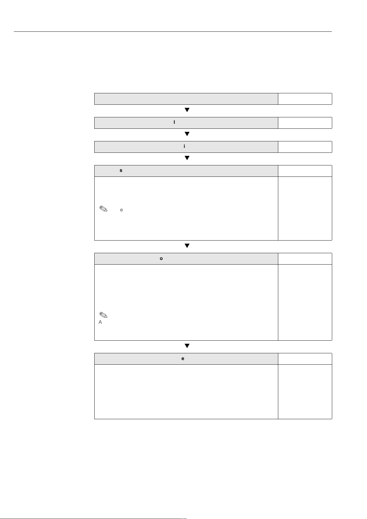
Brief operating instructions
The following brief operating instructions show you how to configure the measuring
device quickly and easily:
Safety instructions Page 7
Installation Page 13
Wiring Page 47
Basic configuration (device parameters, automation functions) Page 78 ff.
Device-specific parameters are configured and the automation functions
specified for the FOUNDATION Fieldbus interface by means of configuration
programs from various manufacturers.
Note!
If the measuring device is equipped with a local display, device-specific para-
meters and functions can be configured easily and quickly using the “Commis-
sioning” Quick Setup menu, e.g. display language, measured variables,
engineering units, etc. →see next page.
Customer-specific configuration
Complex measuring operations mean that additional functions must be config-
ured. Users can select these functions individually by means of appropriate
device parameters and configure and customise them to suit their process
conditions. There are two options open:
– Setting parameters via the configuration program (FF) → Page 64
– Setting parameters via the local display (optional) → Page 73 ff.
Note!
All functions and device parameters are described in detail in the “Description
of Device Functions” manual, which is a separate part of these Operating
Instructions.
Trouble-shooting Page 91 ff.
If faults occur after commissioning or during operation always start trouble-
shooting with the checklist on Page 91. The routine takes you directly to the
cause of the problem and the appropriate remedial measures.
Returning Devices
If you return a measuring device to Endress+Hauser for repair or calibration, you
must complete the “Declaration of contamination” form and enclose it with the
device. You will find a preprinted blank of this form at the back of this manual!

PROline Promag 53 FOUNDATION Fieldbus “QUICK SETUP” commissioning
Endress+Hauser 3
“QUICK SETUP” commissioning
Note:
• You return to the QUICK-SETUP COMMISSIONING (1002) cell if you press the ESC
key (
). However, the configuration already made remains valid.
• The system units selected via the Quick Setup are only valid for the local display and
for parameters in the Transducer Blocks. They have no effect on the output values
(volume flow, calculated mass flow, totalizer) which are transmitted via the FOUNDA-
TION Fieldbus.
+
++
EE
-+
ENDRESS+HAUSER
E
ESC
➀
➂
➁
➃
➄
➅
➆
1002
2000
0402
3001
0420
0700
0400
3001
BQS
Commission
Language
Defaults
Quick Setup
HOME-POSITION
Volume Mass QUIT
Configure another unit? NOYES
Unit
Volume Flow
Unit
Totalizer
Unit
Density
Value
Density
Unit
Mass flow
Unit
Totalizer
Selection - System units
QUIT
Selection output
Configure another output?
Autom. configuration of display? NO
NO
YES
Automatic parameterization
of the display
Carrying out another Quick Setup?
T-DAT save/load?
NO
CANCELSAVELOAD
F06-53FFxxxx-19-xx-xx-en-000

“QUICK SETUP” commissioning PROline Promag 53 FOUNDATION Fieldbus
4Endress+Hauser

PROline Promag 53 FOUNDATION Fieldbus Contents
Endress+Hauser 5
Contents
1 Safety instructions . . . . . . . . . . . . . . . . . 7
1.1 Designated use . . . . . . . . . . . . . . . . . . . . . . . . 7
1.2 Installation, commissioning and operation . . . 7
1.3 Operational safety . . . . . . . . . . . . . . . . . . . . . . 7
1.4 Return . . . . . . . . . . . . . . . . . . . . . . . . . . . . . . . 8
1.5 Notes on safety conventions and icons . . . . . . 8
2 Identification . . . . . . . . . . . . . . . . . . . . . . 9
2.1 Device designation . . . . . . . . . . . . . . . . . . . . . 9
2.1.1 Nameplate of the transmitter . . . . . . . 9
2.1.2 Nameplate of the sensor. . . . . . . . . . 10
2.2 CE mark, declaration of conformity . . . . . . . . 10
2.3 Device certification FOUNDATION Fieldbus . 11
2.4 Registered trademarks . . . . . . . . . . . . . . . . . 11
3 Installation . . . . . . . . . . . . . . . . . . . . . . . . 13
3.1 Incoming acceptance, transport and storage 13
3.1.1 Incoming acceptance . . . . . . . . . . . 13
3.1.2 Transport . . . . . . . . . . . . . . . . . . . . . 13
3.1.3 Storage . . . . . . . . . . . . . . . . . . . . . . . 14
3.2 Installation conditions . . . . . . . . . . . . . . . . . . 15
3.2.1 Dimensions . . . . . . . . . . . . . . . . . . . 15
3.2.2 Mounting location . . . . . . . . . . . . . . . 15
3.2.3 Orientation. . . . . . . . . . . . . . . . . . . . . 17
3.2.4 Inlet and outlet runs . . . . . . . . . . . . . 18
3.2.5 Vibrations . . . . . . . . . . . . . . . . . . . . . 18
3.2.6 Foundations, supports . . . . . . . . . . . 19
3.2.7 Adapters . . . . . . . . . . . . . . . . . . . . . . 20
3.2.8 Nominal diameter and flow rate . . . . 20
3.2.9 Length of connecting cable . . . . . . . 25
3.3 Installation instructions . . . . . . . . . . . . . . . . . 26
3.3.1 Installing the Promag W sensor . . . . 26
3.3.2 Installing the Promag P sensor . . . . . 32
3.3.3 Installing the Promag H sensor. . . . . 38
3.3.4 Turning the transmitter housing . . . . 41
3.3.5 Turning the local display. . . . . . . . . . 42
3.3.6 Installing the wall-mount transmitter
housing . . . . . . . . . . . . . . . . . . . . . . . 43
3.4 Post-installation check . . . . . . . . . . . . . . . . . . 45
4 Wiring . . . . . . . . . . . . . . . . . . . . . . . . . . . . . 47
4.1 Cable specifications for fieldbus . . . . . . . . . . 47
4.2 Connecting the remote version . . . . . . . . . . . 49
4.2.1 Connecting the sensor . . . . . . . . . . . 49
4.2.2 Cable specifications . . . . . . . . . . . . . 53
4.3 Connecting the measuring unit . . . . . . . . . . . 54
4.3.1 Transmitter . . . . . . . . . . . . . . . . . . . . 54
4.3.2 Fieldbus connector . . . . . . . . . . . . . . 57
4.4 Potential equalisation . . . . . . . . . . . . . . . . . . . 58
4.4.1 Standard case . . . . . . . . . . . . . . . . . 58
4.4.2 Special cases . . . . . . . . . . . . . . . . . . 59
4.5 Degree of protection . . . . . . . . . . . . . . . . . . . 61
4.6 Post-connection check . . . . . . . . . . . . . . . . . 62
5 Operation . . . . . . . . . . . . . . . . . . . . . . . . . 63
5.1 Quick operation guide . . . . . . . . . . . . . . . . . . 63
5.2 Operating with the FF configuration
programs . . . . . . . . . . . . . . . . . . . . . . . . . . . . 64
5.3 FOUNDATION Fieldbus technology . . . . . . . . 65
5.3.1 System architecture . . . . . . . . . . . . . 65
5.3.2 Link Active Scheduler (LAS) . . . . . . . 66
5.3.3 Data transfer . . . . . . . . . . . . . . . . . . . 67
5.3.4 Device ID, addressing . . . . . . . . . . . 67
5.3.5 Function blocks . . . . . . . . . . . . . . . . . 67
5.3.6 Field based process control . . . . . . . 68
5.3.7 Device Description . . . . . . . . . . . . . . 68
5.4 Hardware configuration . . . . . . . . . . . . . . . . . 69
5.5 Operation with the local display . . . . . . . . . . . 70
5.5.1 Display and operating elements . . . . 70
5.5.2 Brief operating instruction to the
function matrix . . . . . . . . . . . . . . . . . . 73
5.5.3 Error messages . . . . . . . . . . . . . . . . . 75
6 Commissioning . . . . . . . . . . . . . . . . . . . 77
6.1 Function check . . . . . . . . . . . . . . . . . . . . . . . . 77
6.2 Commissioning . . . . . . . . . . . . . . . . . . . . . . . . 78
6.2.1 Commissioning . . . . . . . . . . . . . . . . . 78
6.2.2 Quick Setup “Commissioning”. . . . . . 83
6.2.3 Empty-pipe/full-pipe adjustment . . . . 84
6.3 Data storage device (DAT, F-Chip) . . . . . . . . 86
7 Maintenance . . . . . . . . . . . . . . . . . . . . . . 87
8 Accessories . . . . . . . . . . . . . . . . . . . . . . . 89
9 Trouble-shooting . . . . . . . . . . . . . . . . . 91
9.1 Trouble-shooting instructions . . . . . . . . . . . . . 91
9.2 System/process error messages . . . . . . . . . . 95
9.3 Process errors without messages . . . . . . . . . 102
9.4 Spare parts . . . . . . . . . . . . . . . . . . . . . . . . . . 104
9.5 Removing and installing printed circuit
boards . . . . . . . . . . . . . . . . . . . . . . . . . . . . . . 105
9.6 Replacing the device fuse . . . . . . . . . . . . . . 109
9.7 Exchanging replaceable electrodes . . . . . . . 110
9.8 Software history . . . . . . . . . . . . . . . . . . . . . . 112
10 Technical data . . . . . . . . . . . . . . . . . . . 113
10.1 Technical data at a glance . . . . . . . . . . . . . . 113
10.1.1 Application . . . . . . . . . . . . . . . . . . . 113
10.1.2 Function and system design . . . . . . 113
10.1.3 Input . . . . . . . . . . . . . . . . . . . . . . . . 113
10.1.4 Output values (FF) . . . . . . . . . . . . . 113
10.1.5 Power supply . . . . . . . . . . . . . . . . . 115
10.1.6 Performance characteristics . . . . . . 116
10.1.7 Operating conditions . . . . . . . . . . . . 117
10.1.8 Mechanical construction . . . . . . . . . 121
10.1.9 Human interface . . . . . . . . . . . . . . . 125

Contents PROline Promag 53 FOUNDATION Fieldbus
6Endress+Hauser
10.1.10 Certificates and approvals . . . . . . . 125
10.1.11 Ordering information . . . . . . . . . . . 126
10.1.12 Accessories . . . . . . . . . . . . . . . . . . 126
10.1.13 Supplementary documentation . . . 126
10.2 Measuring-tube specifications . . . . . . . . . . . 127
10.3 Dimensions wall-mounted housing . . . . . . . 129
10.4 Dimensions Promag 53 W . . . . . . . . . . . . . . 130
10.5 Dimensions Promag 53 P . . . . . . . . . . . . . . . 134
10.6 Dimensions of ground disks (Promag W, P) 139
10.7 Dimensions Promag 53 H . . . . . . . . . . . . . . 140
10.8 Process connections Promag H (DN 2…25) 144
10.9 Process connections of Promag H
(DN 40…100) . . . . . . . . . . . . . . . . . . . . . . . . 152
Index . . . . . . . . . . . . . . . . . . . . . . . . . . . . 157

PROline Promag 53 FOUNDATION Fieldbus 1 Safety instructions
Endress+Hauser 7
1 Safety instructions
1.1 Designated use
The measuring device described in these Operating Instructions is to be used only for
measuring the flow rate of conductive fluids in closed pipes. A minimum conductivity of
20 µS/cm is required for measuring demineralized water. Most fluids can be metered,
provided they have a minimum conductivity of 5 µS/cm, for example:
•acids, alkalis, pastes, mashes, pulps,
•drinking water, wastewater, sewage sludge,
•milk, beer, wine, mineral water, yogurt, molasses, etc.
The manufacturer accepts no liability for damages resulting from incorrect use or use
not as designated.
1.2 Installation, commissioning and operation
Note the following points:
•Installation, connection to the electricity supply, commissioning and maintenance of
the device must be carried out by trained, qualified specialists authorized to perform
such work by the facility's owner-operator. The specialist must have read and under-
stood these Operating Instructions and must follow the instructions it contains.
•The device must be operated by persons authorized and trained by the facility's
owner-operator. Strict compliance with the instructions in the Operating Manual is
mandatory.
•Endress+Hauser will be happy to assist in clarifying the chemical resistance proper-
ties of parts wetted by special mediums, including mediums used for cleaning.
•If welding work is performed on the piping system, do not ground the welding appli-
ance through the Promag flowmeter.
•The installer must ensure that the measuring system is correctly wired in accordance
with the wiring diagrams. The transmitter must be grounded, unless the power supply
is galvanically insulated.
•Invariably, local regulations governing the opening and repair of electrical devices
apply.
1.3 Operational safety
Note the following points:
•Measuring systems for use in hazardous environments are accompanied by separate
“Ex documentation”, which is an integral part of these Operating Instructions. Strict
compliance with the installation instructions and ratings as stated in this supplemen-
tary documentation is mandatory. The symbol on the front of this supplementary Ex
documentation indicates the approval and the test center (
Europe,
USA,
Canada).
•The measuring device complies with the general safety requirements in accordance
with EN 61010, the EMC requirements of EN 61326/A1, and NAMUR recommendation
NE 21.
•Depending on the application, the seals of the process connections of the Promag H
sensor require periodic replacement.
•The manufacturer reserves the right to modify technical data without prior notice.
Your E+H distributor will supply you with current information and updates to these
Operating Instructions.

1 Safety instructions PROline Promag 53 FOUNDATION Fieldbus
8Endress +Hauser
1.4 Return
The following procedures must be carried out before a flowmeter requiring repair or
calibration, for example, is returned to Endress+Hauser:
•Always enclose a duly completed “Declaration of contamination”form. Only then can
Endress+Hauser transport, examine and repair a returned device.
•Enclose special handling instructions if necessary, for example a safety data sheet as
per EN 91/155/EEC.
•Remove all residues. Pay special attention to the grooves for seals and crevices which
could contain residues. This is particularly important if the substance is hazardous to
health, e.g. flammable, toxic, caustic, carcinogenic, etc.
Note:
You will find a preprinted blank of the “Declaration of contamination”form at the back of
this manual.
Caution:
•Do not return a measuring device if you are not absolutely certain that all traces of
hazardous substances have been removed, e.g. substances which have penetrated
crevices or diffused through plastic.
•Costs incurred for waste disposal and injury (burns, etc.) due to inadequate cleaning
will be charged to the owner-operator.
1.5 Notes on safety conventions and icons
The devices are designed to meet state-of-the-art safety requirements, have been
tested, and left the factory in a condition in which they are safe to operate. The devices
comply with the applicable standards and regulations in accordance with EN 61010
“Protection Measures for Electrical Equipment for Measurement, Control, Regulation
and Laboratory Procedures”. They can, however, be a source of danger if used incor-
rectly or for other than the designated use.
Consequently, always pay particular attention to the safety instructions indicated in
these Operating Instructions by the following icons:
Warning:
“Warning”indicates an action or procedure which, if not performed correctly, can result
in injury or a safety hazard. Comply strictly with the instructions and proceed with care.
Caution:
“Caution”indicates an action or procedure which, if not performed correctly, can result
in incorrect operation or destruction of the device. Comply strictly with the instructions.
Note:
“Note”indicates an action or procedure which, if not performed correctly, can have an
indirect effect on operation or trigger an unexpected response on the part of the device.
PROline Promag 53 FOUNDATION Fieldbus 2 Identification
Endress+Hauser 9
2 Identification
2.1 Device designation
The compact version of the “Promag 53”flow measuring system consists of the follow-
ing components:
•Promag 53 transmitter
•Promag W, Promag P or Promag H sensor
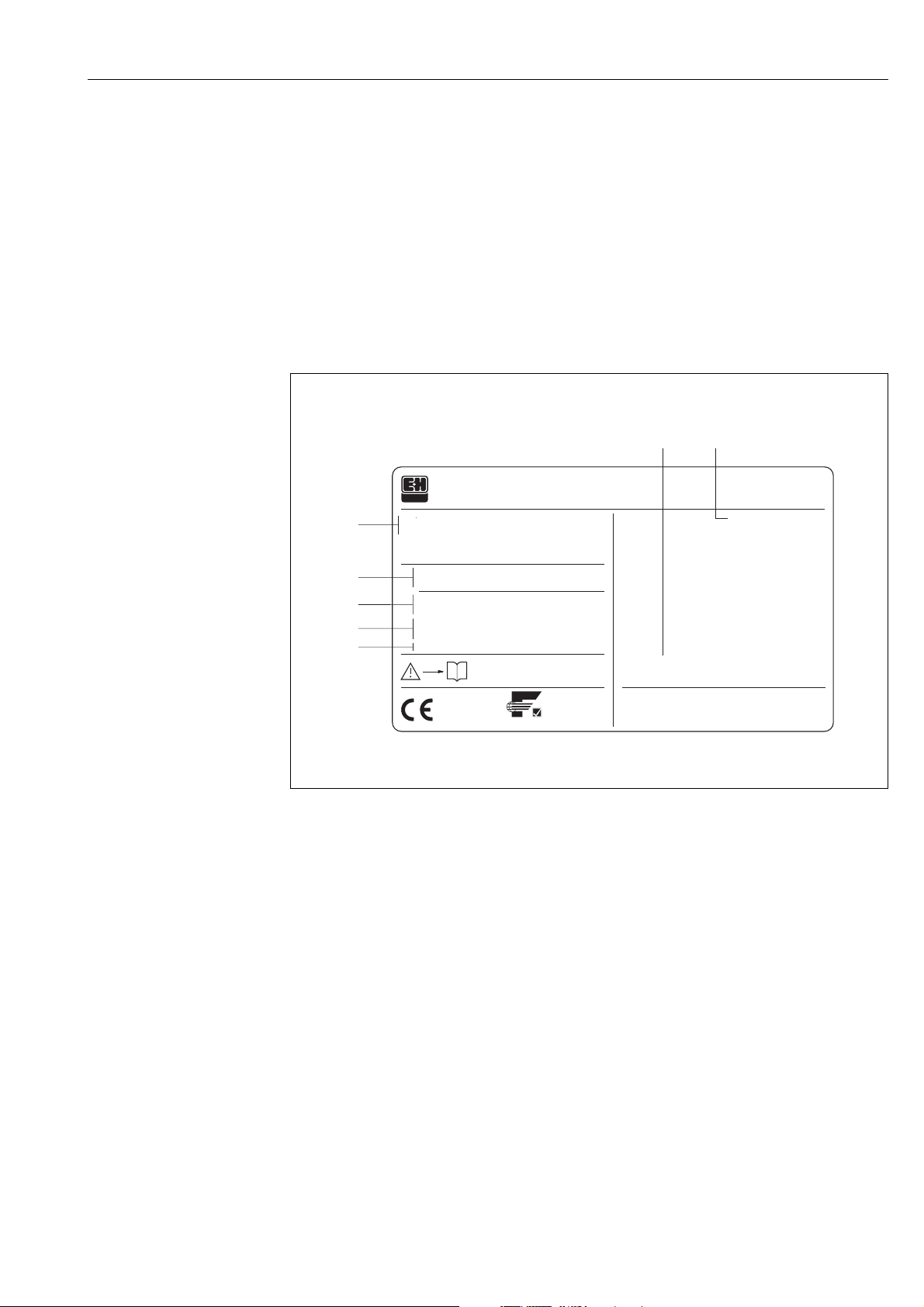
2.1.1 Nameplate of the transmitter
Fig. 1: Nameplate specifications for the “Promag 53” transmitter (example)
1 Ordering code/serial number: See the specifications on the order confirmation for the meanings of the
individual letters and digits.
2 Power supply / frequency: 16...62 V DC / 20...55 V AC / 50...60 Hz
Power consumption: 15 VA / W
3 Additional functions and software:
– EPD/MSU: with Empty Pipe Detection
– etc.
4 FOUNDATION Fieldbus: Equipped with FOUNDATION Fieldbus-H1 interface
ITK 4.0: certified by the Fieldbus FOUNDATION; Interoperability Test Kit, revision 4.0
DEVICE ID: FOUNDATION Fieldbus device identification
5 Reserved for information on special products
6 Ambient temperature range
7 Degree of protection
PROMAG
ENDRESS+HAUSER
Order Code:
53
Ser.No.:
TAG No.:
16-62VDC/20-55VAC
50-60Hz
EPD/MSU
FOUNDATION Fieldbus ITK 4.0
DEVICE ID 452B481042-21000191000
15VA/W
IP67/NEMA/Type4XXXXXX-XXXXXXXXXXXX
21000191000
–20°C (–4°F) < Tamb < +50°C (+120°F)
i
1
7
6
2
3
4
5
ABCDEFGHJKLMNPQRST
Pat. US 5,323,156 5,479,007
Pat. US 4,382,387 4,704,908 5,351,554
FOUNDATION
F06-53xFFxxx-18-06-xx-xx-000
2 Identification PROline Promag 53 FOUNDATION Fieldbus
10 Endress +Hauser
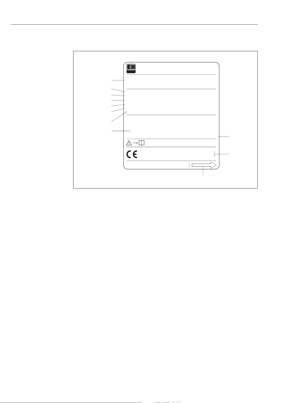
2.1.2 Nameplate of the sensor
Fig. 2: Nameplate specifications for the “Promag” sensor (example)
1 Ordering code/ serial number: See the specifications on the order confirmation for the meanings of the
individual letters and digits.
2 Calibration factor: 0.5328; zero point: −5
3 Nominal diameter: DN 100
Pressure rating: DIN PN 16 bar
4 TMmax +80 °C (max. fluid temperature)
5 Materials:
– Lining: hard rubber (HG)
– Measuring electrodes: stainless steel 1.4435
6 Additional information (examples):
– EPD/MSU: with Empty Pipe Detection electrode
– R/B: with reference electrode
– EME/AWE: with exchangeable measuring electrodes
– 0.2% CAL: with 0.2% calibration
7 Reserved for information on special products
8 Ambient temperature range
9 Degree of protection
10 Reserved for additional information on device version (approvals, certificates)
11 Flow direction
2.2 CE mark, declaration of conformity
The devices are designed to meet state-of-the-art safety requirements, have been
tested, and left the factory in a condition in which they are safe to operate. The devices
comply with the applicable standards and regulations in accordance with EN 61010
“Protection Measures for Electrical Equipment for Measurement, Control, Regulation
and Laboratory Procedures”.
The measuring system described in these Operating Instructions is therefore in
conformity with the statutory requirements of the EC Directives. Endress+Hauser
confirms successful testing of the device by affixing to it the CE mark.
F06-xxxxxxxx-18-05-xx-xx-000
i
1
2
3
4
5
6
7
9
10
11
8
ABCDEFGHJKLMNPQRST
TAG No.:
Pat. UK EP 219 725 EP 521169
Pat. UK EP 541 878 EP 618 680
IP67/NEMA/Type4X
HG / 1.4435
0.5328 / –5
TMmax.:
80°C
EPD/MSU R/B EME/AWE 0.2% CAL
DN100 DIN PN 16
K-factor:
Materials:
ENDRESS+HAUSER
12345678901
XXXXX-XXXXXXXXXXXX
PROMAG
Order Code:
Ser.No.:
X
–20°C(–4°F) < Tamb < +60°C+140°F

PROline Promag 53 FOUNDATION Fieldbus 2 Identification
Endress+Hauser 11
2.3 Device certification FOUNDATION Fieldbus
The Promag 53 flowmeter has passed all the test procedures implemented and has
been certified and registered by the Fieldbus FOUNDATION. The flowmeter thus meets
all the requirements of the specifications listed below:
•Certified according to Fieldbus FOUNDATION specification
•The flowmeter meets all the specifications of the FOUNDATION Fieldbus-H1.
•Interoperability Test Kit (ITK), revision 4.0: The device can also be operated in
conjunction with other-make certified devices.
•Physical Layer Conformance Test by Fieldbus FOUNDATION
2.4 Registered trademarks
KALREZ ®, VITON ®and TEFLON ®
are registered trademarks of E.I. Du Pont de Nemours & Co., Wilmington, USA
TRI-CLAMP ®
is a registered trademark of Ladish & Co., Inc., Kenosha, USA
FOUNDATION Fieldbus™
is a registered trademark of Fieldbus FOUNDATION, Austin, USA
S-DAT™, T-DAT™, F-Chip™, FieldTool™, FieldCheck™, Applicator™
Registered or registration-pending trademarks of Endress+Hauser Flowtec AG,
Reinach, CH

2 Identification PROline Promag 53 FOUNDATION Fieldbus
12 Endress +Hauser

PROline Promag 53 FOUNDATION Fieldbus 3 Installation
Endress+Hauser 13
3 Installation
3.1 Incoming acceptance, transport and storage
3.1.1 Incoming acceptance
•Check the packaging and the contents for damage.
•Check the shipment, make sure nothing is missing and that the scope of supply
matches your order.
3.1.2 Transport
The following instructions apply to unpacking and to transporting the device to its final
location:
•Transport the devices in the containers in which they are delivered.
•Do not remove the protective plates or caps on the process connections until the
device is ready to install. This is particularly important in the case of sensors with
Teflon linings.
Special notes on flanged devices
Caution:
•The wooden covers mounted on the flanges before the device leaves the factory
protect the linings on the flanges during storage and transportation. Do not remove
these covers until immediately before the device is installed in the pipe.
•Do not lift flanged devices by the transmitter housing, or the connection housing in the
case of the remote version.
Transporting flanged devices (DN ≤300):
Use webbing slings slung round the two process connections (Fig. 3). Do not use
chains, as they could damage the housing.
Warning:
Risk of injury if the measuring device slips. The center of gravity of the assembled meas-
uring device might be higher than the points around which the slings are slung.
At all times, therefore, make sure that the device does not unexpectedly turn around its
axis or slip.
Fig. 3: Transporting transmitters with DN ≤ 300
F06-xxxxxxxx-22-00-00-xx-000

3 Installation PROline Promag 53 FOUNDATION Fieldbus
14 Endress +Hauser
Transporting flanged devices (DN ≥ 350):
Use only the metal eyes on the flanges for transporting the device, lifting it and position-
ing the sensor in the piping.
Caution:
Do not attempt to lift the sensor with the tines of a fork-lift truck beneath the metal casing.
This would buckle the casing and damage the internal magnetic coils.
Fig. 4: Transporting sensors with DN ≥ 350
3.1.3 Storage
Note the following points:
•Pack the measuring device in such a way as to protect it reliably against impact for
storage (and transportation). The original packaging provides optimum protection.
•The permissible storage temperature is −10...+50 °C (preferably +20 °C).
•Do not remove the protective plates or caps on the process connections until the
device is ready to install. This is particularly important in the case of sensors with
Teflon linings.
F06-5xFxxxxx-22-xx-xx-xx-001

PROline Promag 53 FOUNDATION Fieldbus 3 Installation
Endress+Hauser 15
3.2 Installation conditions
3.2.1 Dimensions
Dimensions and the fitting lengths of the transmitter and sensor are on Page 129 ff.
3.2.2 Mounting location
Correct measuring is possible only if the pipe is full. Avoid the following locations:
•Highest point in the run. Risk of air accumulating
•Directly upstream from an open pipe outlet in a down pipe.
Fig. 5: Location
Installation of pumps
Do not install the sensor on the intake side of a pump. This precaution is to avoid low
pressure and the consequent risk of damage to the lining of the measuring tube.
Information on the lining's resistance to partial vacuum can be found on Page 120.
It might be necessary to install pulse dampers in systems incorporating reciprocating,
diaphragm or peristaltic pumps. Information on the measuring system's resistance to
vibration and shock can be found on Page 117.
Fig. 6: Installation of pumps
F06-5xxxxxxx-11-00-00-xx-000
F06-5xxxxxxx-11-00-00-xx-001
3 Installation PROline Promag 53 FOUNDATION Fieldbus
16 Endress +Hauser
Partially filled pipes
Partially filled pipes with gradients necessitate a drain-type configuration. The Empty
Pipe Detection function (see Page 84) offers additional protection by detecting empty
or partially filled pipes.
Caution:
Risk of solids accumulating. Do not install the sensor at the lowest point in the drain. It
is advisable to install a cleaning valve.
Fig. 7: Installation in partially filled pipe
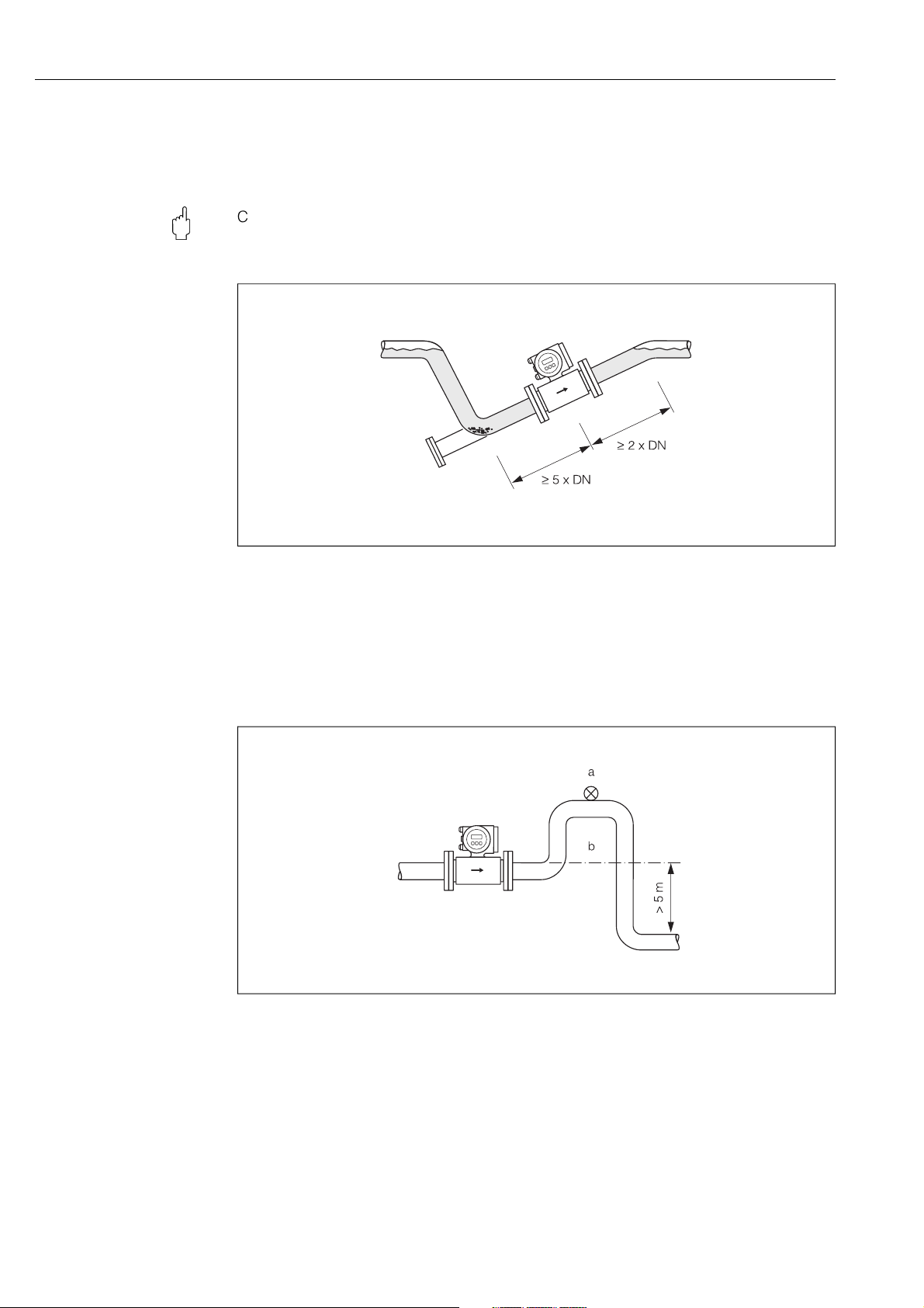
Down pipes
Install a siphon or a vent valve downstream of the sensor in down pipes longer than
5 meters. This precaution is to avoid low pressure and the consequent risk of damage
to the lining of the measuring tube. These measures also prevent the system losing
prime, which could cause air inclusions.
Information on the lining's resistance to partial vacuum can be found on Page 120.
Fig. 8: Measures for installation in a down pipe (a = vent valve; b = siphon)
F06-5xxxxxxx-11-00-00-xx-002
F06-5xxxxxxx-11-00-00-xx-003
PROline Promag 53 FOUNDATION Fieldbus 3 Installation
Endress+Hauser 17
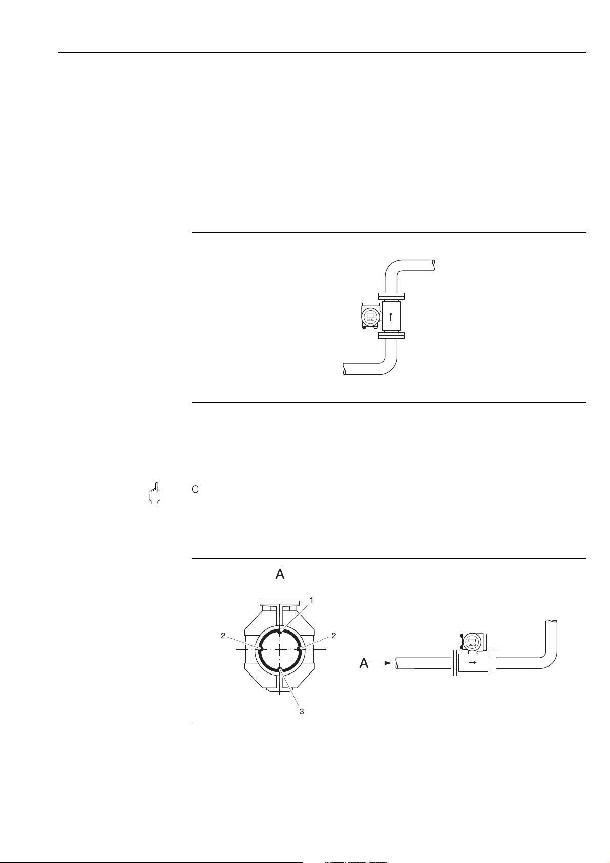
3.2.3 Orientation
An optimum orientation position helps avoid gas and air accumulations and deposits in
the measuring tube. Promag, nevertheless, supplies a range of functions and accesso-
ries for correct measuring of problematic fluids:
•Empty Pipe Detection (EPD) ensures the detection of partially filled measuring tubes,
e.g. in the case of degassing fluids or varying process pressures (see Page 84)
•Exchangeable measuring electrodes for abrasive fluids (see Page 110)
Vertical orientation
This is the ideal orientation for self-emptying piping systems and for use in conjunction
with Empty Pipe Detection.
Fig. 9: Vertical orientation
Horizontal orientation
The measuring-electrode plane should be horizontal. This prevents brief insulation of
the two electrodes by entrained air bubbles.
Caution:
Empty Pipe Detection functions correctly with the measuring device installed horizon-
tally only when the transmitter housing is facing upward (Fig. 10). Otherwise there is no
guarantee that Empty Pipe Detection will respond if the measuring tube is only partially
filled or empty.
Fig. 10: Horizontal orientation
1 EPD electrode for the detection of empty pipes (not with Promag H, DN 2…8)
2 Measuring electrodes (signal detection)
3 Reference electrode for potential equalisation (not with Promag H)
F06-5xxxxxxx-11-00-00-xx-004
F06-5xxxxxxx-11-00-xx-xx-000

3 Installation PROline Promag 53 FOUNDATION Fieldbus
18 Endress +Hauser
3.2.4 Inlet and outlet runs
If possible, install the sensor well clear of fittings such as valves, T-pieces, elbows, etc.
Compliance with the following requirements for the inlet and outlet runs is necessary in
order to ensure measuring accuracy.
•Inlet run ≥ 5 x DN
•Outlet run ≥2 x DN
Fig. 11: Inlet and outlet runs
3.2.5 Vibrations
Secure the piping and the sensor if vibration is severe.
Caution:
It is advisable to install sensor and transmitter separately if vibration is excessively
severe. Information on resistance to vibration and shock can be found on Page 117.
Fig. 12: Measures to prevent vibration of the measuring device
F06-5xxxxxxx-11-00-00-xx-005
> 10 m
F06-5xxxxxxx-11-00-00-xx-006
PROline Promag 53 FOUNDATION Fieldbus 3 Installation
Endress+Hauser 19
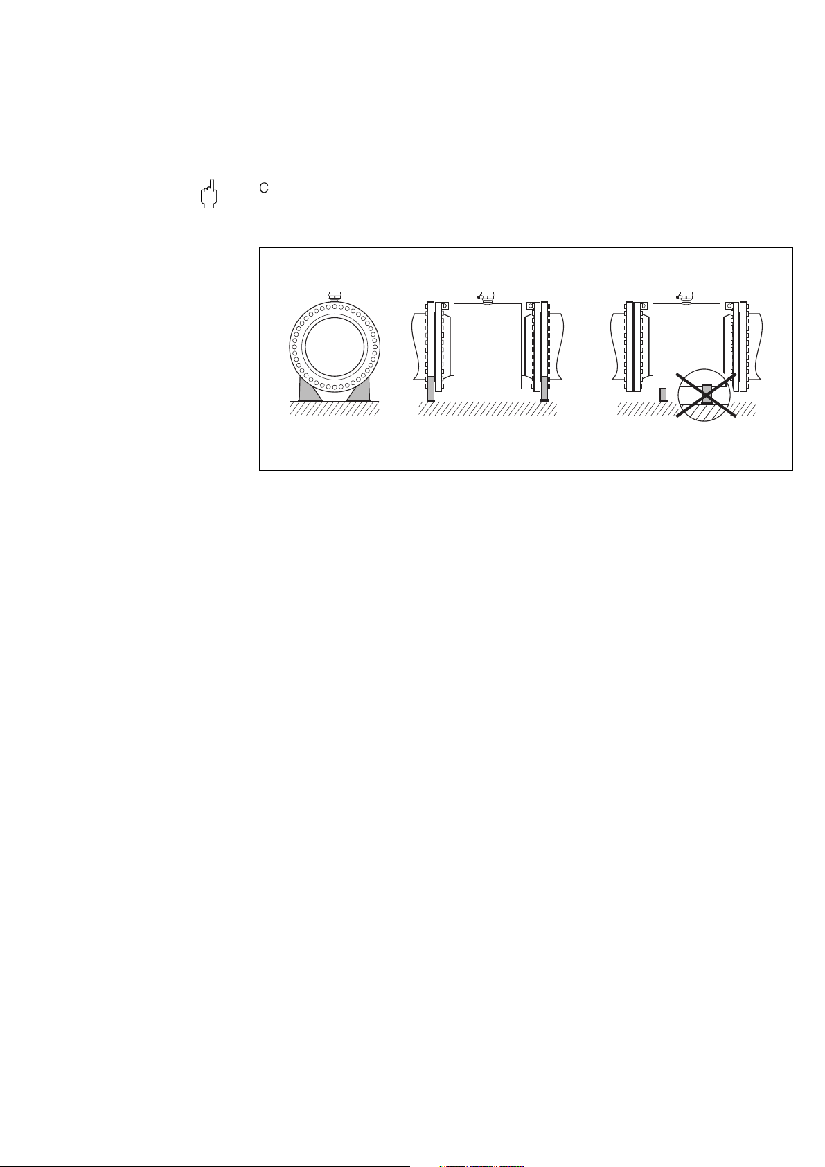
3.2.6 Foundations, supports
If the nominal diameter is DN ≥ 350, mount the transmitter on a foundation of adequate
load-bearing strength.
Caution:
Risk of damage. Do not support the weight of the sensor on the metal casing:
the casing would buckle and damage the internal magnetic coils.
Fig. 13: Correct support for large nominal diameters (DN ≥350)
F06-5xFxxxxx-11-05-xx-xx-000

3 Installation PROline Promag 53 FOUNDATION Fieldbus
20 Endress +Hauser
3.2.7 Adapters
Suitable adapters to (E) DIN EN 545 (double-flange reducers) can be used to install the
sensor in larger-diameter pipes. The resultant increase in the rate of flow improves
measuring accuracy with very slow-moving fluids.
The nomogram shown here can be used to calculate the pressure loss caused by cross-
section reduction:
Note:
The nomogram applies to fluids of viscosity similar to water.
1. Calculate the ratio of the diameters d/D.
2. From the nomogram read off the pressure loss as a function of flow velocity
(downstream from the reduction) and the d/D ratio.
Fig. 14: Pressure loss due to adapters
3.2.8 Nominal diameter and flow rate
The diameter of the pipe and the flow rate determine the nominal diameter of the sensor.
The optimum velocity of flow is 2...3 m/s. The velocity of flow (v), moreover, has to be
matched to the physical properties of the fluid:
•v < 2 m/s: for abrasive fluids such as potter's clay, lime milk, ore slurry, etc.
•v > 2 m/s: for fluids producing build-up such as wastewater sludge, etc.
Note:
Flow velocity can be increased, if necessary, by reducing the nominal diameter of the
sensor (see Page 20).
F06-5xxxxxxx-05-05-xx-xx-000
Table of contents


