Ushio UIT-250 User manual

USHIO INC.
System Company


i
1000033244-00
Thank you for purchasing the Accumulated UV Meter UIT-250.
This manual provides a summary for the Accumulated UV Meter UIT-250 as well as
instructions for its use.
Keep this manual in a safe place in order to be able to refer to it at any time.
Precautions for use
These "precautions for use" describe information that needs to be followed in order to use
this product correctly and safely. Read this portion carefully and make sure that you
understand it before moving on.
Sections that display this warning are content where
"Failure to heed could lead to heavy injury or death".
Sections that display this are content where "Failure to
heed could lead to injury or physical damage".
This is noted for items concerning operation and main-
tenance of the equipment that are important to know or
if not in compliance or corrected damage may be caused
to the unit.
Warning
•The UV leaking from the UV curing system can damage you eyes or skin within
a short period of time. When using the UIT-250 near a leaking UV, be sure to wear
protective glasses, and do not expose your skin directly to the UV. The recom-
mended protectors are:
- Protective glasses: RS-24U (SPL3~5) manufactured by Riken Optics.
- Protective mask: UV protector mask manufactured by USHIO INC.
(Drawing No. 2046-1981)
•The heat shield cover may be heated to a high temperature of 60°C or more when
the UIT-250 is placed on the conveyor of a UV curing system (UNICURE). Be
sure to handle this cover carefully so as not to cause and injury, such as a burn.
Warning
Caution
Imporant
Read the following warnings prior to use of the
unit.

ii 1000033244-00
Caution
•When placing the UV radiation hardening equipment on a conveyor, attach a heat
shield cover on the UIT-250. If used without attaching a heat shield cover, there
is the possibility that the operating panel will be damaged beyond repair.
•Allow 1 minute intervals between measurements.
If measurement is repeated without allowing for sufficient cooling, the unit will
overheat and measurements can no longer be performed.
•The temperature limitation for use is 300°C for no longer than 10 seconds.
When using a sampling rate of 16 samples/second, as accumulation over 4 min-
utes and distribution measurement are possible, be careful when taking measure-
ments at high temperature.
•The photodetector is formed using optical components; therefore pay attention
to the environment (temperature and humidity). Especially the optical filter
which demonstrates prescribed functionality within the specified temperature
and humidity environment. In conditions outside the specified environment func-
tionality can not be demonstrated and the element itself deteriorates. Store in a
location where the environment such as the temperature and humidity can be
controlled such as using a desiccator.
•Do not apply any shock to the UIT-250 unit and the photodetector. Otherwise,
the incorporated devices may be broken or fail to operate properly.
•When replacing the photodetector, be careful not to touch the gold-plated con-
nector. Touching the connector may cause rust. If you accidentally touch the
photodetector, wipe it with alcohol-soaked gauze.
•Use alcohol to clean the UIT-250 unit. Do not use any organic solvent such as
thinner or acetone since it damages the unit body.
Read the following cautions prior to use of the
unit.

iii
1000033244-00
Important
•Both the UIT-250 unit and the photodetector have individual sensitivity adjust-
ment controls. Do not touch these control; they are used for calibration by
USHIO only.
•A very weak current flows through the UIT-250 unit form the battery even if the
power is off. Remove the battery when not using the unit for a long period of
time.
•Note that if serial communication is used with the UIT-250 consumption current
increases and the batteries are consumed at a faster rate.
•If a separate-type photodetector is used, be sure to check that the model and
serial number of the photodetector unit match those of the sensitivity adjustment
adaptor. When changing the measured wavelength, you must change both the
photodetector unit and the sensitivity adjustment adaptor.
•When using the temperature sensor, check that the model of the sensitivity
adjustment adaptor is UVD-TK.
•If there are particles on the photodetector or if it is dirty it can cause error in the
measurement.
Check to make sure that there are not any particles and that the photodetector is
not dirty. If it is dirty, wipe it with a piece of gauze soaked in alcohol.
•When turning on the unit, prevent light from reaching the photodetector.
When the unit is turned on the exposure amount meter is initialized and the
irradiance value is set to 0. Therefore, if the unit is turned on while photodetector
is exposed to light the irradiance value is still set to 0. All measurement values
made thereafter will contain error (will be offset).
•If the irradiance exceeds the full scale degree of irradiance a scale over condition
occurs and the display monitor indicates the maximum value for the current
measurement range. Raise the measurement range to perform the measurement.
•If the measured temperature exceeds the full scale value, it is regarded as over-
scale and is indicated in the display monitor.
If the measured temperature drops into the temperature indication range, the
temperature is indicated again.
Read the following important points prior to
use.

iv 1000033244-00
•The UIT-250 has an internal temperature sensor to protect the internal electric
circuit. If the unit is used in conditions that exceed the permissible temperature
range an overheat error (temperature abnormality) is set and is
indicated on the display monitor.
In order to reset the error, turn the unit off and allow it to cool naturally.
•If is indicated on the display monitor, it is regarded as a battery
voltage error. This indicates that the battery level is low. Replace the battery. Be
sure to check that the power is turned off when replacing the battery.
•The UIT-250 is provided with an auto-power-off function. If five minutes have
elapsed after an operation key is pressed, the UIT-250 is automatically powered
off. You can reset this auto-power-off condition by pressing the key.
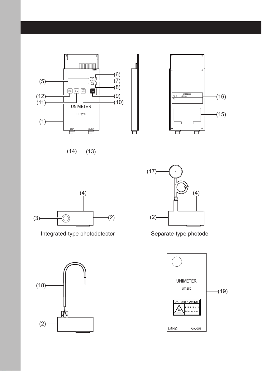
•This photodetector unit differs from the conventional photodetector models,
such as UVD-254PD, UVD-365D, and UVD-405PD, in spectral sensitivity and
angle characteristics. Therefore, note that it does not indicate the same irradiance
value as those models for a normal light source. When the UIT-250 is placed on
the conveyor of a UNICURE UV curing system, it indicates irradiance 1.5 times
larger than the value measured by UVD-365PD. This photodetector unit is pro-
vided with a large photodetector of 10 mm in diameter that is also able to receive
the light at an angle. Thus, it allows measurement for the accumulated UV amount
received by a radiated object (a workpiece) at high precision.
•The sensitivity of this photodetector is calibrated using monochromatic light.
Multiple photodetectors of the same type provide the same indication for mea-
surement of designated monochromatic light - light sources. When the light source
emits a wavelength distribution take into consideration the spectroscopic sensi-
tivity characteristics of the photodetector shown in chapters 35 and 36 of this
operating manual. These spectroscopic sensitivity characteristics are representa-
tive values. When measuring a general light source that has a wavelength distribu-
tion, there is variability in the value indicated by multiple photodetectors of the
same type due to variability in the spectroscopic sensitivity characteristics of
the units.
•Equipment shown in this catalog, any products using the equipment or technolo-
gies relating the equipment fall under the category of security control relating
freight or technologies under the provisions of the Foreign Exchange and Foreign
Trade Control Law. You have to obtain permission from the Government of
Japan before exporting them from Japan.

1
1000033244-00
4. Instructions for use
Contents
Precautions for use ............................................................... i
Contents ............................................................................... 1
1. Outline .............................................................................. 2
2. Configuration .................................................................... 3
3. Names for each of the Sections ....................................... 4
4. Instructions for use ........................................................... 6
4-1. Preparation prior to measurement ............................................. 6
4-1-1. Insertion and replacement of batteries ........................................................ 6
4-1-2. Setup and replacement of the photodetector and sensitivity
adjustment module ...................................................................................... 7
4-1-3. Setup and replacement of temperature sensor thermocouple ................... 9
4-1-4. Setup of heat shield cover ......................................................................... 10
4-1-5. Auto-power-off function .............................................................................. 12
4-2. Measurement Method ............................................................. 13
4-2-1. Toggling the rise and sample rate ............................................................. 13
4-2-2. Turning unit off ........................................................................................... 14
4-2-3. Real time irradiance (temperature) measurement .................................... 14
4-2-4. Peak irradiance (temperature) measurement ........................................... 15
4-2-5. Accumulated exposure amount measurement ......................................... 16
4-3. Output of Measurement Results ..............................................17
4-3-1. Analog output ............................................................................................. 17
4-3-2. Output of irradiance (temperature) distribution ......................................... 18
4-4. Serial Communication Function ............................................... 20
4-4-1. Connection with personal computer .......................................................... 22
4-4-2. Commands ................................................................................................ 23
4-4-3. Output of irradiance distribution ................................................................ 24
5. Error Display...................................................................26
6. Troubleshooting .............................................................. 27
7. Warranty and Repair ...................................................... 28
7-1. Warranty .................................................................................. 28
7-2. Repair ...................................................................................... 28
7-3. Calibration (Main Unit and Photodetector Unit) ........................ 28
8. Specifications ................................................................. 29
9. Disclaimer ...................................................................... 32

21000033244-00
4. Instructions for use
1. Outline
The UIT-250 is a compact Accumulated UV Meter. By changing the photodetector
unit, it can measure the UV irradiance and temperature in three wavelength regions.
Mounted with the heat shield cover, the UIT-250 can be placed directly on the con-
veyor of a UV curing system (USHIO's UNICURE).
Mode Power
Start
Stop
H/M/L
mW/cm
2
(
°
C)
P.mW/cm
2
(P.
°
C)
mJ/cm
2
UNIMETER
UIT-250
SIO I/F ANA.OUT
UIT-250 Unit
1. Outline

3
1000033244-00
4. Instructions for use
2. Configuration
Please check the components that are provided with the unit.
Mode Power
Start
Stop
H/M/L
mW/cm
2
(°C)
P.mW/cm
2
(P.°C)
mJ/cm
2
UNIMETER
UIT-250
SIO I/F ANA.OUT
UNIMETER
UIT-250
ANA.OUT
[Options for sale separately]
[UIT-250]
UIT-250 unit
Integrated-type photodetector
(UVD-C254, C365, C405)
2 m extension cable
Temperature sensor
(UVD-TK)
Heat shield cover
Separate-type photodetector
(UVD-S254,S365,S405)
Operating manual Trunk case
Precision driver
(NDV-size 3 phillips)
AAA alkaline
batteries (3)
* The heat shield cover for
UIT-150 can not be used.
Analog signal
output cable
(2441-8961)
Connector model:
HR10-7P-6P
(Hirose)
Serial
communication cable
(3157-0133)
Connector model:
HR10-7P-5P
(Hirose)
2. Configuration

41000033244-00
4. Instructions for use
3. Names for each of the Sections
USHIO.INC
TYPE
NO.
UIT-250
Mode Power
Start
Stop
H/M/L
mW/cm2
(°C)
P.mW/cm2
(P.°C)
mJ/cm2
UNIMETER
UIT-250
SIO I/F ANA.OUT
UNIMETER
UIT-250
ANA.OUT
(1)
(2)
(4)
(6)
(7)
(17)
(18)
(13)
(3)
(4)
(5)
(8)
(9)
(10)
(11)
(12)
(14)
(15)
(2)
(2)
(19)
(16)
Integrated-type photodetector Separate-type photodetector
Temperature Sensor Heat shield cover
Main unit
3. Names for each of the Sections

5
1000033244-00
4. Instructions for use
(1) UIT-250 unit
(2) Sensitivity adjustment module
(3) Photodetector
(4) Nameplate of photodetector model
Indicates the model of the photodetector.
(5) Display monitor
Used for displaying irradiance value and temperature.
(6) Real time irradiance indicator
Blinks during measurement of real time irradiance (temperature).
(7) Peak irradiance indicator
Blinks during measurement of peak irradiance (temperature).
(8) Accumulated exposure amount indicator
Blinks when measuring accumulated exposure amount.
(9) Power switch
Used for turning the power on and off.
(10) Start/stop switch
Used for starting and stopping of measurement.
(11) Mode Switch
Used for toggling between measurement modes.
(12) H/M/L switch
Used for toggling the measurement range.
(13) Analog signal output terminal
Used to output an analog signal.
(14) Serial communication terminal
Used for connecting the serial communication cable.
(15) Battery cover
Three AAA batteries are stored inside.
(16) Primary nameplate
Nameplate for the UIT-250 unit
(17) Photodetector
(18) Thermocouple
Chromel - alumel thermocouple.
(19) Heat shield cover
Protects UIT-250 from heat and UV light.
3. Names for each of the Sections

61000033244-00
4. Instructions for use
4-1. Preparation prior to measurement
4-1-1. Insertion and replacement of batteries
(1) Use the precision driver that came with the unit to remove the screw (one loca-
tion) that is holding the battery cover on the rear surface in place and remove
the battery cover.
(2) Insert 3 AAA batteries according to the direction indicated on the exposure
meter body.
(3) Attach the battery cover and fix it in place using a screw.

7
1000033244-00
4. Instructions for use
4-1-2. Setup and replacement of the photodetector and sensitivity
adjustment module
Through replacing the photodetector for the UIT-250, 3 wavelength ranges of UV
exposure amount and temperature can be measured.
•Setup of the photodetector and sensitivity adjustment module
(1) Make sure the power is off.
(2) Hang the fold back portion of the photodetector on the main unit.
Mode Power
Start
Stop
mW/cm
2
(
°
C
)
P.mW/cm
2
(P.
°
C
)
mJ/cm
2
ER
Fold back portion
Hanging section
(3) Direct the photodetector to the back of the exposure amount meter and rotate it.
Mode Power
Start
Stop
H/M/L
mW/cm
2
(
°
C
)
P.mW/cm
2
(P.
°
C
)
mJ/cm
2
UNIMET
ER
UIT

81000033244-00
4. Instructions for use
(4) Using the precision driver that came with the unit, fix the photodetector to the
UIT-250 upper back side using the 2 screws that came with the unit.
(5) When using a separate-type photodetector, connect a separate photodetector
where the model and serial number match that of the sensitivity adjustment
module.
(6) When using a temperature sensor, confirm that the model of the sensitivity
adapter is "UVD-TK" and connect it to the temperature sensor section.
•Removal of the photodetector and/or sensitivity adjustment module
(1) Remove 2 screws from the upper back side of the UIT-250 using the precision
driver that came with the unit.
(2) Cause the photodetector to face the front of the exposure meter and rotate the
photodetector.
(3) When the fold portion of the photodetector is removed from the body, the pho-
todetector can be removed.

9
1000033244-00
4. Instructions for use
4-1-3. Setup and replacement of temperature sensor thermocouple
(1) Use a k-type thermocouple.
Important
The unit will not indicate correct values if thermocouples other than k-
type thermocouples are used.
Do no use thermocouples other than k-type thermocouples.
(2) Loosen the knurled screw that is on top of the sensitivity adjustment module.
- This shows a hole for insertion of a terminal.
(3) Insert the chromel - alumel wire into the hole for insertion of a terminal.
- Viewing from the front surface of the exposure meter, insert the alumel wire
into the right terminal.
Chromel (Yellow) is (+) and Alumel (Red) is (−) for the associated thermo-
couple.
Chromel (+)
(Yellow)
Alumel (−)
(Red)
(4) Tighten the knurled screw.
Important
If high irradiance light is radiated, the temperature of the thermocouple
tip may rise earlier than the temperature of the workpiece.
Using adhesive or embedding, cause as much contact as possible be-
tween the work piece and the tip of the thermocouple.

10 1000033244-00
4. Instructions for use
4-1-4. Setup of heat shield cover
Attaching a heat shield cover on the UIT-250 protects the main body of the UIT-250
from heat and UV rays.
(1) Match the groove in the light protection cover with the cover of the exposure
meter main unit and slide it up starting at the bottom of the exposure meter.
UNIMETER
UIT-250
ANA.OUT
Mode Power
Start
Stop
H/M/L
mW/cm
2
(
°
C
)
P.mW/cm
2
(P.
°
C
)
mJ/cm
2
SIO I/F ANA.OUT
UNIMETER
UIT-250
(2) With the heat shield cover in place, attach the flat head screws that came with
the unit to both sides of the unit.
UNIMETER
UIT-250
ANA.OUT

11
1000033244-00
4. Instructions for use
(3) When viewing the operation panel surface, slide the heat shield cover.
The heat shield cover is prevented from being removed from the UIT-250 by
stoppers.
(4) When performing measurement, slide the heat shield cover until only the pho-
todetector surface can be seen.
The heat shield cover and UIT-250 are fixed in place by magnets.
(5) When removing the heat shield cover from the UIT-250, remove the flat head
screws from both sides of the unit with the heat shield cover fully in place and
slide the heat insulation panel towards the bottom of the exposure meter body.
Warning
When placing on the conveyor of the UV radiation hardening equip-
ment (UNICURE) that has a conveyor, the heat shield cover surface
may rise above 60°C. This is a possible cause of burns etc. therefore
care must be taken when handling.

12 1000033244-00
4. Instructions for use
4-1-5. Auto-power-off function
The UIT-250 has an auto-power-off function.
The unit automatically turns off after 5 minutes elapses from when the operation switch
is pushed.
The auto-power-off function is enabled when we ship the unit.
This function can be disabled using the following procedure.
Important
1. Remove the batteries prior to performing the operation.
2. Do not set a setting other than designated.
This can cause failure or malfunction.
(1) Stand the exposure meter up and remove the batteries.
- Reference "4-1-1. Insertion and replacement of batteries" for removal of bat-
teries.
(2) Remove the screws (4 locations) from the rear surface cover of the UIT-250.
(3) When you can see the control board, change the setting for the dip switch: S1
on the circuit board according to the following instructions.
- Change the second switch to ON.
UIT-250
condition
Auto power off enabled
(setting when shipped) Auto power off disabled
Settings of
dip
switches

13
1000033244-00
4. Instructions for use
4-2. Measurement Method
4-2-1. Toggling the rise and sample rate
The UIT-250 performs selection of sample rate simultaneous with turning the unit on.
(1) Selection of sample rate is performed when the unit is turned on.
•When selecting 32 samples/second
- Prevent light from reaching the photodetector surface and push the
switch.
- A sample rate of 32 samples/second is selected.
-is indicated on the display monitor.
•When selecting 16 samples/second
- Prevent light from reaching the photodetector surface and push the
switch while holding down the switch.
- A sample rate of 16 samples/second is selected.
-is indicated on the display monitor.
Important
1. Connect either a photodetector or a temperature sensor prior to turn-
ing the unit on. If the photodetector or temperature sensor is connected
after turning the unit on, an incorrect value will be displayed.
2. Prevent light from reaching the photodetector surface when turning the
unit on.
(2) Numbers are shown on the display monitor and all indicators are blinking.
(3) Initialization finishes in roughly 5 seconds and real time irradiance measure-
ment mode is entered.
Important
The sample rate is only selected when the unit is turned on.
When toggling of the sample rate is desired, first turn the unit off and
then turn it back on.

14 1000033244-00
4. Instructions for use
4-2-2. Turning unit off
(1) Push the switch for roughly 1 second.
- Numbers on the display monitor disappear.
- The power is turned off.
4-2-3. Real time irradiance (temperature) measurement
(1) When the UIT-250 is turned on, it enters H range real time irradiance measure-
ment mode.
- The real time irradiance indicator is blinking.
- The average value for 0.5 seconds is indicated on the display monitor.
- When a temperature sensor is connected, the thermocouple temperature is
indicated on the display panel.
(2) Push the switch to change the measurement range.
- The measurement range changes from H range →M range →L range →
H range each time the switch is pushed.
- Reference table 1 for display of each measurement range and for full scale
values.
Note, the measurement range is not selected when a temperature sensor is
connected.
Table 1 Indication ranges of irradiance values and temperature
Model
UVD-C254
UVD-S254
(mW/cm2)
UVD-C365
UVD-S365
(mW/cm2)
UVD-C405
UVD-S405
(mW/cm2)
UVD-TK
(°C)
H range 0 ~ 9999 0 ~ 9999 0.0 ~ 999.9
M range 0.0 ~ 999.9 0.0 ~ 999.9 0.00 ~ 99.99
Indication
limits L range 0.00 ~ 99.99 0.00 ~ 99.99 0.000 ~ 9.999
0.0~350.0
(3) When the switch is pushed, the real time irradiance value is held.
- The real time irradiance indicator light turns on.
The hold can be canceled by pushing the switch a second time.
- When in analog output, output is continuous whether the switch is pushed
or not.
Table of contents
Other Ushio Measuring Instrument manuals