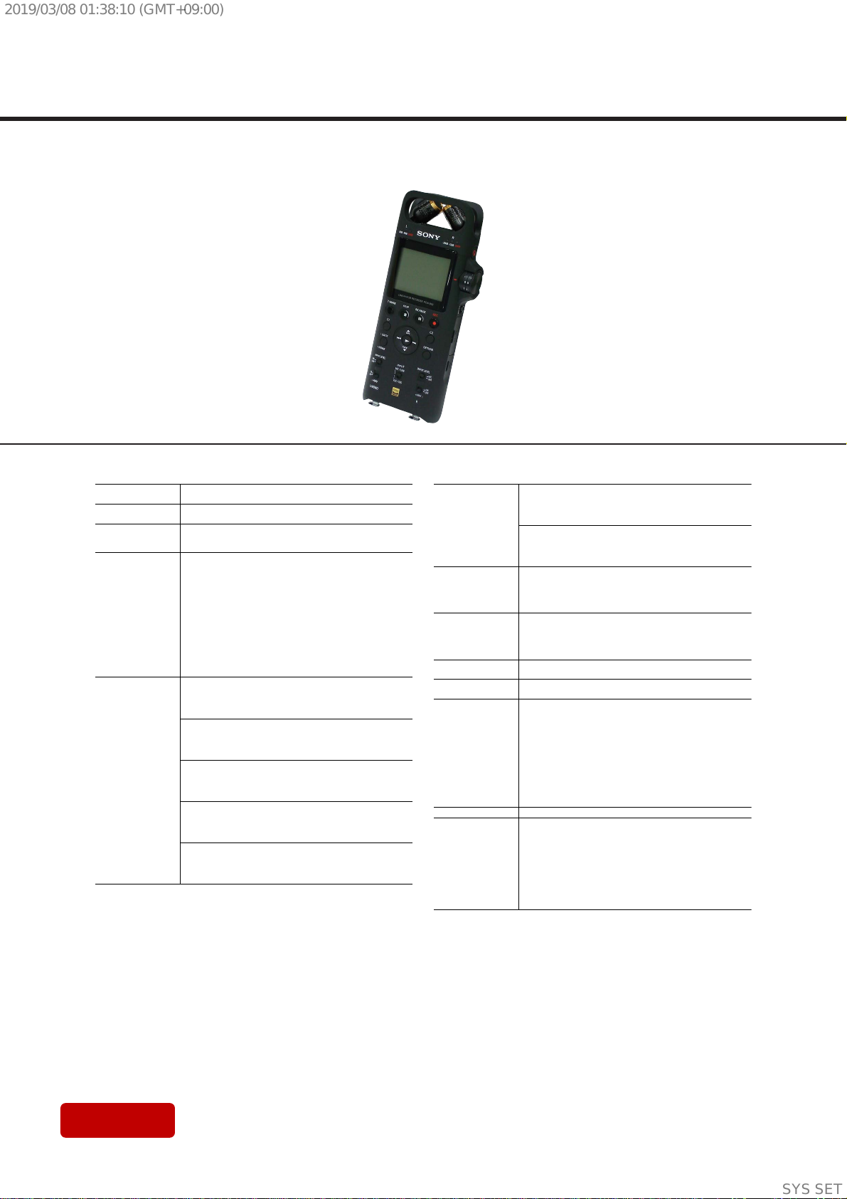
PCM-D10
4
Sony CONFIDENTIAL
For Authorized Servicer
Copyrights
tAll rights reserved. This manual or the software
described herein, in whole or in part, may not be
reproduced, translated or reduced to any machine
readable form without prior written approval from
Sony Corporation.
tDisplay windows in this manual may dier from
what are actually displayed on your linear PCM
recorder depending on the country or region you
purchased the linear PCM recorder and the settings
you have made.
tWhat you record is for personal enjoyment and use
only. Copyright laws prohibit other forms of use
without the permission of the copyright holders.
Trademarks and licenses
tMicrosoft, Windows and Windows Media are
registered trademarks or trademarks of Microsoft
Corporation in the United States and/or other
countries.
tSDXC, SDHC, SD, microSDXC, microSDHC and
microSD logos are trademarks of SD-3C,LLC.
tApple, the Apple logo, iPhone,Mac, and macOS are
trademarks of Apple Inc., registered in the U.S.and
other countries.
App Store is a service mark of Apple Inc.,registered
in the U.S. and other countries.
tUse of the Made for Apple badge means that an
accessory has been designed to connect specically
to the Apple product(s) identied in the badge,and
has been certied by the developer to meet Apple
performance standards.Apple is not responsible for
the operation of this device or its compliance with
safety and regulatory standards.
tCompatible iPhone models
iPhone X, iPhone 8, iPhone 8 Plus,iPhone 7,
iPhone 7 Plus, iPhone SE, iPhone 6s, iPhone 6s Plus,
iPhone 6, iPhone 6 Plus, iPhone 5s,iPhone 5c,
iPhone 5
tAndroid and Google Play are trademarks of Google
LLC.
tThe BLUETOOTH® word mark and logos are
registered trademarks owned by Bluetooth SIG, Inc.
and any use of such marks by Sony Corporation is
under license. Other trademarks and trade names
are those of their respective owners.
tSound Forge Audio Studio 12 is a registered
trademark of MAGIX Software GmbH.
tThe N-Mark is a trademark or registered trademark
of NFC Forum, Inc. in the United States and in other
countries.
tUSB Type-C™ and USB-C™ are trademarks of USB
Implementers Forum.
tAll other trademarks and registered trademarks
are trademarks or registered trademarks of their
respective holders. Furthermore,“™” and“®” are not
mentioned in each case in this manual.
tMPEG Layer-3 audio coding technology and patents
licensed from Fraunhofer IIS and Thomson.
tThis product is protected by certain intellectual
property rights of Microsoft Corporation. Use or
distribution of such technology outside of this
product is prohibited without a license from
Microsoft or an authorized Microsoft subsidiary.
Notes on the License
his linear PCM recorder comes with software
that are used based on licensing agreements
with the owners of that software.
Based on requests by the owners of copyright
of these software applications,we have an
obligation to inform you of the following.
Please read the following sections.
Licenses (in English) are recorded in the
built-in memory of your linear PCM recorder.
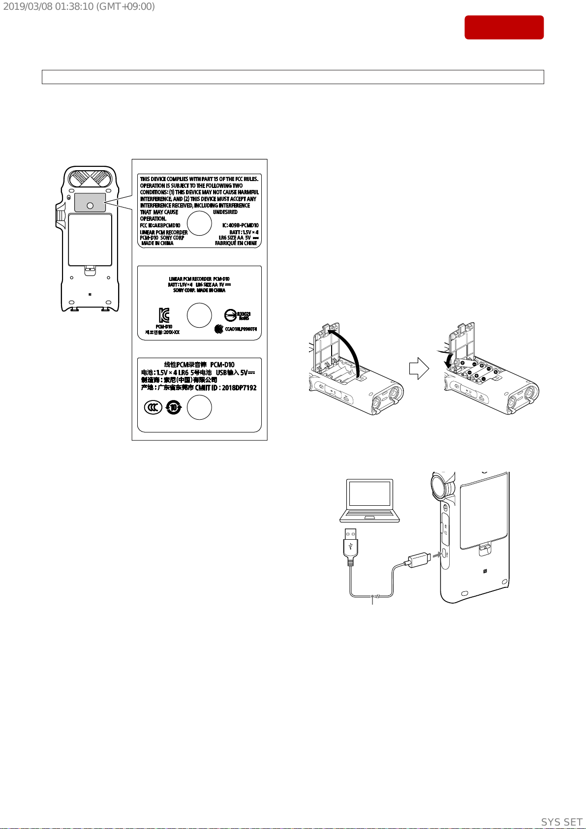
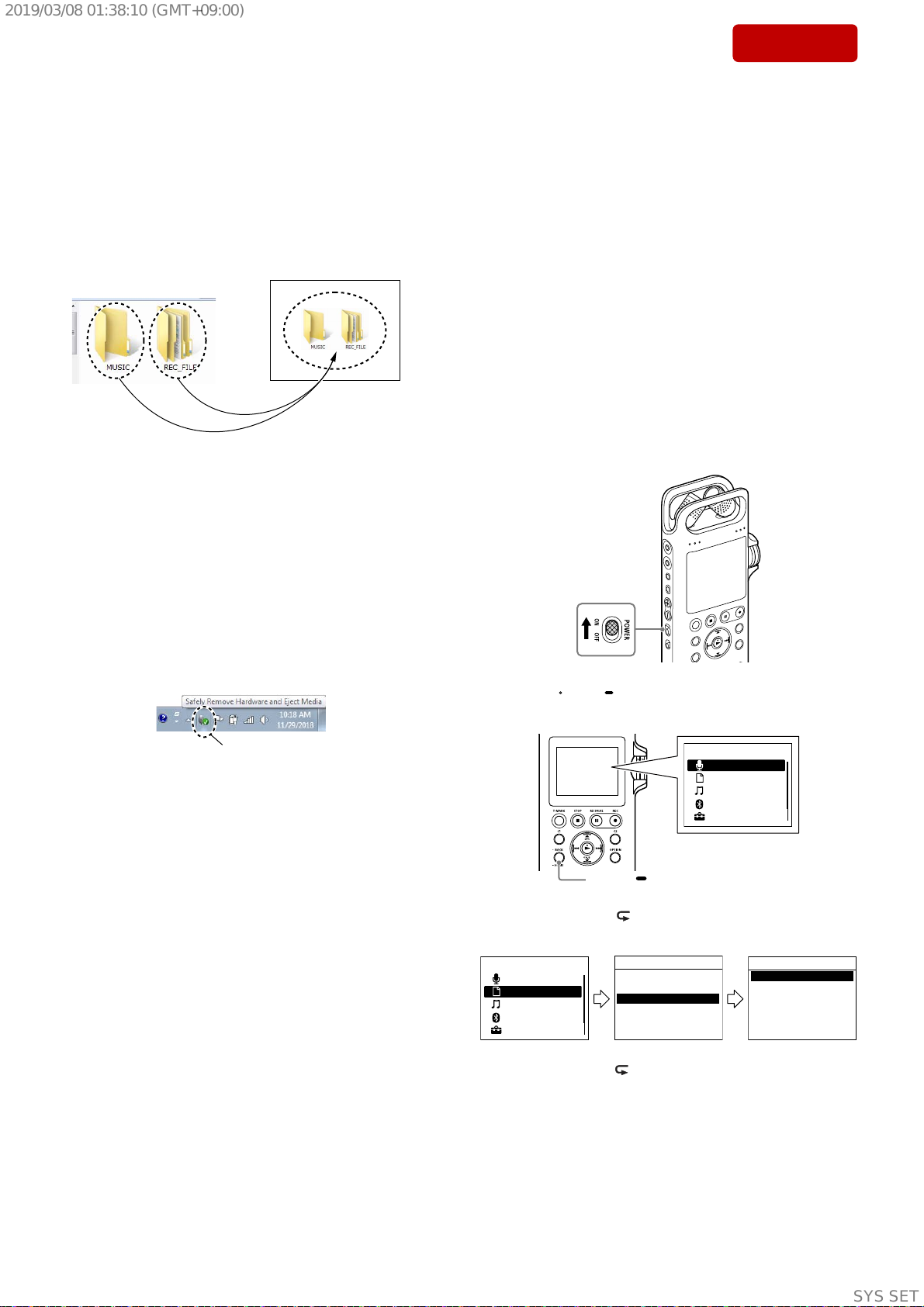
Establish a Mass Storage connection between
the linear PCM recorder and a computer to
read licenses in the“LICENSE” folder.
On GNU GPL/LGPL applied
software
he software that is eligible for the following
GNU General Public License (hereinafter
referred to as “GPL”) or GNU Lesser General
Public License (hereinafter referred to as
“LGPL”) are included in the linear PCM
recorder.
his informs you that you have a right to have
access to, modify, and redistribute source
code for these software programs under the
conditions of the supplied GPL/LGPL.
Source code is provided on the web.Use the
following URL to download it.
http://www.sony.net/Products/Linux/
We would prefer you do not contact us about
the contents of source code.
Licenses (in English) are recorded in the built-
in memory of your linear PCM recorder.
Establish a Mass Storage connection between
the linear PCM recorder and a computer to
read licenses in the“LICENSE” folder.
1. SERVICING NOTES ................................................ 5
2. DISASSEMBLY
2-1. Disassembly Flow.............................................................. 24
2-2. Rear Guard (MIC).............................................................. 25
2-3. Ornament (XLR)................................................................ 25
2-4. Ornament (REC VOL), Knob REC VOL Assy,
L Knob (REC VOL)........................................................... 26
2-5. Checking Operation of the Knob (REC VOL) .................. 27
2-6. Rear Cabinet Block............................................................ 28
2-7. Cabinet (Rear) Assy ........................................................... 29
2-8. Lid (SD Card), Side Knob (Input) ..................................... 30
2-9. Screw (Tripod), LINE SW Board ...................................... 31
2-10. MIC_JACK Board ............................................................. 32
2-11. MIC Assy ........................................................................... 33
2-12. HP_LINE_JACK Board .................................................... 34
2-13. Chassis Block/Front Block-1 ............................................. 35
2-14. Chassis Block/Front Block-2 ............................................. 36
2-15. Chassis Block/Front Block-3 ............................................. 37
2-16. LCD Module ...................................................................... 38
2-17. SW_L Board ...................................................................... 39
2-18. Chassis (Main) ................................................................... 39
2-19. NFC Antenna ..................................................................... 40
2-20. REC Volume Assy.............................................................. 41
2-21. CAP Board ......................................................................... 41
2-22. MAIN Board Block ........................................................... 42
2-23. MAIN Board ...................................................................... 43
2-24. Chassis (Rear), Battery Terminal....................................... 44
2-25. XLR Assy........................................................................... 45
2-26. Button (VOL)..................................................................... 46
2-27. Chassis (SD Card) Block ................................................... 46
2-28. SW_R Board ...................................................................... 47
2-29. SW Board Block ................................................................ 48
2-30. SW Board........................................................................... 49
2-31. Cabinet Front Assy............................................................. 50
3. TEST MODE ............................................................... 51
4. EXPLODED VIEWS
4-1. Rear Guard (MIC) Section................................................. 58
4-2. Rear Cabinet Section ......................................................... 59
4-3. LINE SW Board Section.................................................... 60
4-4. MIC Section....................................................................... 61
4-5. Chassis Section .................................................................. 62
4-6. LCD Module, REC Volume Section.................................. 63
4-7. MAIN Board Section ......................................................... 64
4-8. XLR Assy, SW Board Section ........................................... 65
4-9. Front Cabinet Section ........................................................ 66
5. ACCESSORIES .......................................................... 67
TABLE OF CONTENTS
SYSSET
2019/03/0801:38:10(GMT+09:00)


 User manual")