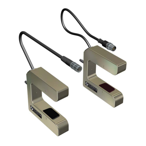
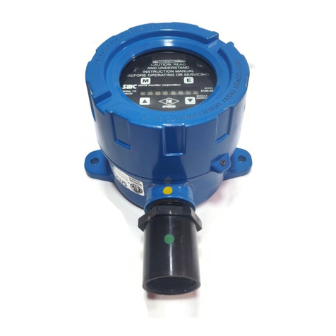
Fife Maxcess DSE-45 Series User manual

DSE-45
Wideband Ultrasonic Sensor
User Manual
EN
MI 2-315 1 A
FIFE GUIDING SOLUTIONS

CONTENTS
www.maxcessintl.com
DSE-45
MI 2-315 1 A
INTRODUCTION 1.1
About these operating instructions .............................................................................. 1.1
Target groups ....................................................................................................... 1.1
Read operating instructions .................................................................................. 1.1
Proper use.................................................................................................................... 1.2
Improper use ............................................................................................................... 1.2
Definition of terms ....................................................................................................... 1.4
SAFETY 2.1
Important safety information ....................................................................................... 2.1
Signal words ................................................................................................................ 2.1
Symbols used............................................................................................................... 2.2
Personnel requirements ............................................................................................... 2.3
Qualified electrician ..................................................................................................... 2.3
Preventing hazards ...................................................................................................... 2.4
INSTALLATION 3.1
Transport and storage.................................................................................................. 3.1
Mounting ..................................................................................................................... 3.1
Mounting location ................................................................................................. 3.1
Product dimensions............................................................................................... 3.2
Mounting the sensor .................................................................................................... 3.3
DSE-45 sensor connections ......................................................................................... 3.4
Power connection .................................................................................................. 3.4
Network connection .............................................................................................. 3.5
Optional network communication settings ..................................................... 3.5
OPERATION OVERVIEW 4.1
DSE-45 Sensor ............................................................................................................. 4.1
Analog outputs ..................................................................................................... 4.1
Digital outputs ...................................................................................................... 4.2
Sensor jobs ........................................................................................................... 4.2
Operation modes .................................................................................................. 4.3
Single proportional band mode ...................................................................... 4.3
Multiple proportional band mode ................................................................... 4.4
MODBUS/TCP INTERFACE 5.1
Default signals ............................................................................................................. 5.1
Default data ................................................................................................................. 5.2
Remote control ............................................................................................................ 5.4
WEB PAGE ACCESS 6.1
DSE-45 web page tab descriptions............................................................................... 6.2
Home .................................................................................................................... 6.2
Info ....................................................................................................................... 6.3
Network ................................................................................................................ 6.4

CONTENTS
www.maxcessintl.com
DSE-45
MI 2-315 1 A
Analog output configuration ................................................................................. 6.5
Analog output parameter descriptions ........................................................... 6.6
Calibration ............................................................................................................ 6.7
OPERATOR INTERFACE 7.1
DSE-45 home screen.................................................................................................... 7.1
Key (button) definitions......................................................................................... 7.2
Menu navigation.................................................................................................... 7.4
JOB SETTINGS 8.1
Setting up a job............................................................................................................ 8.1
Set sensor mode .......................................................................................................... 8.2
Single proportional band....................................................................................... 8.2
Multiple proportional band.................................................................................... 8.3
Proportional band size ................................................................................... 8.4
Edge learning ................................................................................................. 8.4
Virtual sensor linking ..................................................................................... 8.4
Select job ..................................................................................................................... 8.5
Select job menu structure ..................................................................................... 8.5
Calibrate transducers ............................................................................................ 8.6
Control options ............................................................................................................ 8.7
Configuration............................................................................................................... 8.8
Network ....................................................................................................................... 8.9
SPECIFIC PROCEDURES 9.1
Jog virtual sensors ....................................................................................................... 9.1
Application filtering ..................................................................................................... 9.2
MAINTENANCE 10.1
SPECIFICATIONS 11.1
SERVICE 12.1

CONTENTS
www.maxcessintl.com
DSE-45
MI 2-315 1 A
TABLE OF FIGURES
Figure 1. Product dimensions.............................................................................................. 3.2
Figure 2. Sensor offset to web pass line .............................................................................. 3.3
Figure 3. DSE-45 sensor connections ................................................................................. 3.4
Figure 4. Single proportional band ...................................................................................... 4.3
Figure 5. Multiple proportional band................................................................................... 4.4
Figure 6. Modbus/TCP default signals ................................................................................ 5.1
Figure 7. Modbus default data ............................................................................................ 5.3
Figure 8. DSE-45 web page tabs ......................................................................................... 6.1
Figure 9. DSE-45 home screen............................................................................................ 7.1
Figure 10. Job setting menu structure................................................................................. 8.1
Figure 11. Select job menu structure .................................................................................. 8.5
Figure 12. Hardware settings menu structure ..................................................................... 8.6
Figure 13. Control options menu structure ......................................................................... 8.7
Figure 14. Configuration menu structure ............................................................................ 8.8
Figure 15. Network menu structure .................................................................................... 8.9
Figure 16. Service menu structure..................................................................................... 8.11
Figure 17. Jog menu structure............................................................................................. 9.1

1.1
INTRODUCTION
www.maxcessintl.com
DSE-45
MI 2-315 1 A
About these operating instructions
These operating instructions describe the installation,
commissioning, operation, and maintenance of the DSE-45 and
provide important instructions for proper use.
Additionally, where applicable, instructions are included for
communications with Fife Controllers/Processors, such as the
Fife D-MAX Web Guide Controller. These instructions are to be
used in addition to those instructions provided with the
controller/processor.
All of the information herein is the exclusive proprietary
property of Maxcess International, and is disclosed with the
understanding that it will be retained in confidence and will
neither be duplicated nor copied in whole or in part nor be
used for any purpose other than for which disclosed.
Copyright 2020. All rights reserved.
Periodically there will be updates to this manual. The latest
version is available on our website or by calling the number on
the back page of this publication.
The operating instructions must be carefully stored and must
always be available at or near the customer's system during the
service life of the sensor.
The original instructions were written in English.
Target groups
These operating instructions are directed to both the system
construction master as well as the operator who uses the
sensor in production line.
Read operating instructions
The operating instructions must be read and used by all
persons who have the responsibility of installing,
commissioning, operating and maintaining the sensor.

1.2
INTRODUCTION
www.maxcessintl.com
DSE-45
MI 2-315 1 A
Proper use
The DSE-45 is used for non-contact measurement of the
lateral offset of a material web being guided in a customer
system. The sensor is suitable for
- Web edge guiding,
- Web center guiding, and
- Web width or edge position measurement.
The sensor can be used to control or measure both opaque and
transparent materials.
The sensor must only be used in accordance with its intended
purpose and in a technically flawless condition.
The sensor must not be changed or opened.
Improper use
Operation outside of the technical specifications is not
permitted.
Operation in areas where there is a danger of explosions is
prohibited.
The sensor may not be used as a support, handle or step.
Any use other than the designated use is not permitted.

1.3
INTRODUCTION
www.maxcessintl.com
DSE-45
MI 2-315 1 A
Operation principle
The DSE-45 Ultrasonic Sensor utilizes scanning technology to
detect on-web and off-web transition edges of web material
that is located within the sensor field of view. This allows new
edges to be detected at any time. The scanning orientation is
from the closed end of the sensor to the open end of the
sensor. The position of the detected edges in relation to either
the sensor default proportional band or the user configured
proportional band is then applied to the output signals of the
sensor. Both analog and digital output signals are provided.
The DSE-45 Ultrasonic Sensor can be used in conjunction with
the Fife Controllers/Processors as a guiding system. If the
sensor is connected to a D-MAX Operator Interface via an
Ethernet connection, multiple menus are available for
configuring the sensor. It can also be used as a "stand-alone"
for web width monitoring or edge position monitoring.

1.4
INTRODUCTION
www.maxcessintl.com
DSE-45
MI 2-315 1 A
Definition of terms
Controller/Processor –The electronics processing unit that
controls and drives the actuators that are attached to it, in
response to position feedback from the sensors.
MAC Address –(Media Access Control). This is the factory
assigned hardware address of a DSE-45. MAC Address is also
referred to as MAC-ID.
MAXNET –This is the Fife proprietary Ethernet protocol that is
used for communications between DSE-45 and D-MAX devices.
This is a deterministic protocol. Therefore, the MAXNET
network must be isolated from other Ethernet networks that do
not follow this protocol.
Polarity –The direction of movement in response to a
command or error signal.
Strip/Web –The user material that is being guided.
Virtual Sensor –This is a term adopted to describe the way the
DSE-45 handles web edges. A virtual sensor simply defines a
range within the sensor field of view which represents the
signal scaling to be applied to the edge tracked within the
defined range. Each virtual sensor is also polarity-aware so
that it only tracks the edge with the configured polarity. Virtual
sensor sizes can be the entire field of view or can be as small
as 10.2 mm [0.4 in], and since they are just mathematical
ranges, they can overlap in any conceivable manner.

2.1
SAFETY
www.maxcessintl.com
DSE-45
MI 2-315 1 A
Important safety information
To ensure safe and problem-free operation of the DSE-45 it
must be
-properly shipped and stored,
-properly mounted and placed in operation,
-properly used and carefully maintained.
Proper operation and careful maintenance will ensure a long
service life for the sensor.
Please note the following:
-The content of these operating instructions
-Any safety instructions that are printed on the unit
-The requirements of the machine manufacturer
-Applicable national, state and local requirements for
accident prevention and environmental protection
Information about safety instructions
The safety instructions and symbols described in this section
are used in these Operating instructions. They are used to
avoid possible dangers for users and to prevent material
damage.
SIGNAL WORD
Source of danger and its results.
Avoiding dangers
Signal words
The signal word DANGER indicates an immediate danger of
serious injury or death.
The signal word WARNING indicates a possible danger which
could lead to serious injury or death.
The signal word CAUTION refers to a possible danger which
could lead to slight to moderate injury.
The signal word ATTENTION refers to a possible danger which
could lead to material damage.

2.2
SAFETY
www.maxcessintl.com
DSE-45
MI 2-315 1 A
Symbols used
Reference to general hazards that may result in bodily
injuries
Refers to danger of injury caused by crushing
Refers to danger of injury caused by cutting
Refers to general hazards that will result in damage to the
device or system
Qualified electrician
The electrical components may only be connected and
disconnected by a qualified electrician!
Read operating instructions
Follow these operating instructions for proper and safe use.
Keep for future use.
Other markings
Reference to important information

2.3
SAFETY
www.maxcessintl.com
DSE-45
MI 2-315 1 A
Personnel requirements
The tasks listed in these operating instructions may only be
carried out by appropriately qualified personnel commissioned by
the operator. The responsibilities of the personnel for the work on
the system must be clearly defined by the operator.
Transport, assembly, maintenance, troubleshooting, disassembly
Specialized staff
-Mechatronics engineer, industrial mechanic, etc.
Electrical connection or disconnection
Specialized staff
-Only by a qualified electrician
Control during operation
Specialized staff
-Machine and system operators, etc.
-Personnel or trainees trained and supervised by the system
operator
Repair
Specialized staff
-Service technician of Fife-Tidland GmbH
Qualified electrician
A qualified electrician is a person whose specialist training,
knowledge and experience, as well as knowledge of the relevant
standards, enable him to assess and perform the work assigned to
him and to recognize and avoid possible hazards.
The electrician is specially trained for the field in which he or she
works and is familiar with the relevant standards and regulations.

2.4
SAFETY
www.maxcessintl.com
DSE-45
MI 2-315 1 A
Preventing hazards
-No changes may be made to the sensor.
-Electrical lines must not be subjected to any mechanical
loads.
-The parameters specified in
Section 11.1, Specifications
must
be observed.
-Only accessories and replacement parts that have been
approved by Fife Tidland may be used.
-The sensor may not be used as a support, handle or step.
There is a danger that the sensor will become damaged
(breaking off/snapping), resulting in personal injury.
The DSE-45 can be remotely controlled via a network connection.
As with any network-controlled device, when remote control of
the device is implemented, there is the possibility of movement
of the guiding structure when remote commands are issued.
Therefore, any time personnel are near the guiding structure, it is
recommended that standard safeguards be taken to prevent
injury. During servicing of the equipment, to prevent injury to
personnel, it is recommended that standard Lockout/Tagout
procedures be used.

3.1
INSTALLATION
www.maxcessintl.com
DSE-45
MI 2-315 1 A
Transport and storage
-The sensor and/or the unit on which the sensor is mounted
must be secured against slipping during transport
-The sensor must be stored in a cool, clean, and dry place;
see
Ambient Conditions, page 11.1
-The sensor must not be stored in the vicinity of powerful
magnetic fields. The electronic components of the sensor
may be damaged.
Mounting
The DSE-45 Ultrasonic Sensor can be mounted to a square
bar using the optional mounting brackets, or by using the
incorporated mounting holes near the far corners of the
sensor housing. For complete details, refer to the
installation drawings and instruction sheets included with
your shipment.
WARNING
-If a sensor is damaged, it must not be installed or placed
in operation.
-All assembly tasks on the sensor must only be performed
when there is no electrical power in the system.
-Assembly tasks and mechanical settings must only be
performed when the machine has been stopped and
secured from being turned on again.
Mounting location
-Protection Class: IP65
-Operating temperature: 5°C ... 60°C [40°F ... 140°F]
-Relative humidity: maximum 85%
-Operating altitude above sea level:
maximum 5000 meters [16,000 feet]
-Protected from vibrations
-Do not place close to strong magnetic fields;
the electronic components may be damaged.
-Do not place close to strong electrostatic fields;
the electronic components may be damaged.
-Do not mount in places where there is a risk of explosions.

3.2
INSTALLATION
www.maxcessintl.com
DSE-45
MI 2-315 1 A
Product dimensions
1 - Sensor gap (typical for all sensors)
2 - M5 x 20 mm SHCS with lock washer
3 - The minimum bend radius of the optional Ethernet cable is 90 mm [3.54 in].
The minimum bend for output and auxiliary cables is less.
Figure 1. Product dimensions
Sensor model
A
Bandwidth
B
Bandwidth center
C
D
E
DSE-45-7
66.2 [2.606]
59.75 [2.351]
193.2 [7.606]
n/a
175.2 [6.898]
DSE-45-11
107.0 [4.213]
80.0 [3.149]
234.0 [9.213]
n/a
216 [8.504]
DSE-45-18
178.4 [7.024]
115.69 [4.555]
305.0 [12.024]
105.0 [4.134]
287.4 [11.315]
DSE-45-31
311.0 [12.244]
181.98 [7.164]
438.0 [17.244]
210.1 [8.272]
420.0 [16.535]
DSE-45-52
515.0 [20.276]
283.96 [11.179]
642.0 [25.276]
420.0 [16.353]
624.0 [24.567]

3.3
INSTALLATION
www.maxcessintl.com
DSE-45
MI 2-315 1 A
Mounting the sensor
Remove the plastic dust covers from the
connectors that will be in use for your
application.
For complete details, refer to the
installation drawings and instruction
sheets included with your shipment.
4 -
Center line of sensor should be offset
15 degrees or more of perpendicular
to the web pass line.
5 -
Web pass line
6 -
Mounting screws can be relocated in
the sensor as needed for your
installation.
Figure 2. Sensor offset to web pass line

3.4
INSTALLATION
www.maxcessintl.com
DSE-45
MI 2-315 1 A
DSE-45 connections
Disconnect power from the DSE-45 before connecting or
disconnecting any cables.
All cable connectors must be tightened sufficiently to provide
the required connection for the cable shielding.
X1 –
ETHERNET
X2 –
AUXILIARY
Auxiliary power (+10.5 to +51 VDC)
Analog output (web width)
X3 –
OUTPUT
-Connection to controller (default)
-Power input (+10.5 to +28 VDC)
-Analog outputs (edge1, edge2, web width)
-RS-485
Figure 3. DSE-45 connections
Power connection
Power to the DSE-45 should be supplied to either the X2 or X3
Connector, but not to both connectors.
-When used as a ‘stand-alone’ sensor, power should be
applied to the X2 Connector. Follow the voltage
guidelines in Figure 3.
-When used as part of a Fife system, the Controller/
Processor generally supplies power to the X3 connector.
If alternate power is to be supplied, refer to the system
drawings for information on power supply requirements.
Verify that the supply is within the above listed limits.

3.5
INSTALLATION
www.maxcessintl.com
DSE-45
MI 2-315 1 A
Network connection
Optional network communication
settings
-The IP address of each Ethernet device in a network must be
unique to each device in the network. All DSE-45 sensors are
shipped from the factory with the same IP address (10.0.0.150).
If it is necessary to change the IP address of the DSE-45, see
Web Access Network; page 6.1.
-MAXNET is a Fife proprietary protocol used to communicate
between the DSE-45 and other network devices, such as the Fife
D-MAX Controller and D-MAX Operator Interface.
-The MAXNET address of each Ethernet device in a network must
be unique (Address 1-31). The address must not be 0 (zero). If
using the optional Ethernet connection on the DSE-45, you will
need to set the MAXNET address of the sensor. see
Web Access
Network; page 6.1.

4.1
OPERATION OVERVIEW
www.maxcessintl.com
DSE-45
MI 2-315 1 A
DSE-45 outputs
The DSE-45 Ultrasonic Sensor provides analog outputs for
backward compatibility and an Ethernet digital interface for
advanced functions.
The DSE-45 Ultrasonic Sensor can be used in conjunction with
the Fife Controllers/Processors as a guiding system. If the
sensor is connected to a D-MAX Operator Interface via an
Ethernet connection, multiple menus are available for
configuring the sensor.
It can also be used as a "stand-alone" for web width
monitoring or edge position monitoring.
The following sections describe the default and optional
settings for available sensor parameters.
Before changing any of the sensor parameters, verify that the
controller that is using this sensor as a signal source is in
either Manual Mode or Servo Center Mode. Otherwise, there is
the possibility of movement of the guiding structure.

4.1
OPERATION OVERVIEW
www.maxcessintl.com
DSE-45
MI 2-315 1 A
Analog outputs
There are four configurable analog outputs, controlled by three
configurable signal sources. The analog outputs can be
independently configured to produce any combination of the
following signal ranges. The analog output mapping can be
configured for each of the sensor jobs. An Ethernet connection
to the sensor is required for configuration changes.
0 to 10 mA (default)
0 to 20 mA
4 to 20 mA
OFF
Two of the four analog outputs, by default, provide edge
position (the first on-web edge and the first off-web edge
detected in the scan direction).
The other two outputs, by default, provide web width
measurement and are common to each other in function, but
are located on two separate connectors for accessibility in
various applications.
The function assigned to the analog outputs is configurable.
Any signal produced by the DSE-45 can be mapped to the
analog outputs up to and including duplicating the same signal
on all outputs, if desired. An Ethernet connection to the sensor
is required for configuration changes.
The default mode maps the analog channels as follows:
Analog Channel 0 (Analog Output 1) = VS1(Virtual Sensor 1)
Analog Channel 1 (Analog Output 2) = VS2(Virtual Sensor 2)
Analog Channel 2 (Analog Outputs 3 and 4) = WW1(web width)

4.2
OPERATION OVERVIEW
www.maxcessintl.com
DSE-45
MI 2-315 1 A
Digital outputs
The digital outputs are transmitted via a proprietary Fife
MAXNET Serial Protocol over Ethernet, which requires an
optional Ethernet cable connected to a network device.
For more information about the available signals;
see
DSE-45 Web Page, page 6.6.
Sensor jobs
The DSE-45 supports storage for up to eight different jobs. A
job contains the sensor operation mode (single or multiple
proportional bands), the proportional band size, and all
learned virtual sensor parameters.
The DSE-45 default has only a single job enabled and is
configured as a single proportional band.
Recalling a stored job immediately activates the position and
proportional bands for all virtual sensors.
Select job; page 8.5
.
In order to use more than one job, additional configured jobs
must first be enabled;
Control Options, page 8.7.
This manual suits for next models
5
Table of contents
Other Fife Accessories manuals
