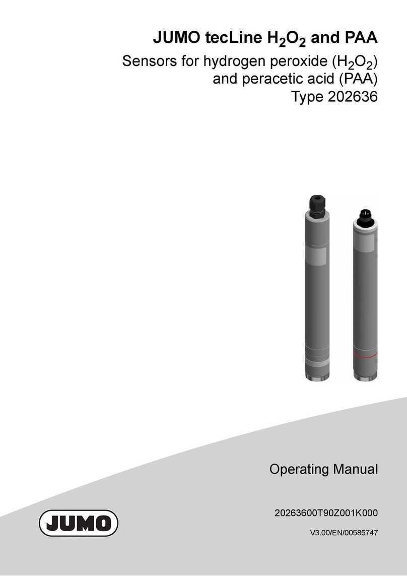
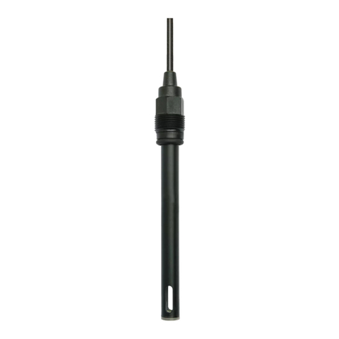
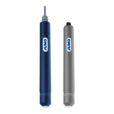
JUMO tecLine ClO2 User manual

JUMO tecLine ClO2 / JUMO tecLine O3
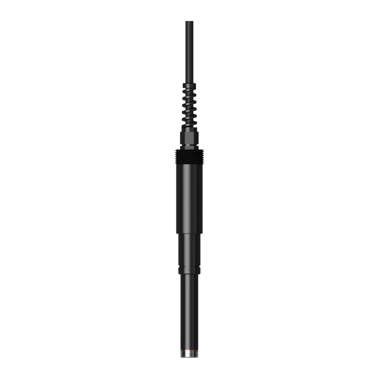
Sensors for chlorine dioxide and ozone
Type 202634/45, type 202634/46
type 202634/50, type 202634/51
B 202634.0
Operating manual
2012-07-13/00585740

Screws coated with threadlocking paint must not be adjusted! The
threadlocking paint must not be damaged. If it is, claims under the
warranty will not be honored!

Contents
1 Typographical conventions ...................................................... 5
1.1 Warning signs ..............................................................................................5
1.2 Note signs ....................................................................................................5
2 General ....................................................................................... 6
2.1 Preface .........................................................................................................6
2.2 Scope of application ....................................................................................6
2.3 Output signal ................................................................................................6
3 Device identification ................................................................. 7
3.1 Nameplate ....................................................................................................7
3.2 Order details .................................................................................................7
4 Description ................................................................................ 8
4.1 Scope of delivery .........................................................................................8
4.2 Sensor for chlorine dioxide - type 202634/45 ..............................................8
4.3 Sensor for chlorine dioxide - type 202634/46
(resistant to chemicals and surfactants) ......................................................8
4.4 Sensor for ozone - type 202634/50 .............................................................8
4.5 Sensor for ozone - type 202634/51
(resistant to chemicals and surfactants) ......................................................9
4.6 Details ..........................................................................................................9
4.7 Technical data ............................................................................................11
5 Mounting .................................................................................. 13
5.1 Notes ..........................................................................................................13
5.2 Flow-through fitting (part no. 00392611) ...................................................14
5.3 Flow monitoring .........................................................................................16
6 Electrical connection .............................................................. 17
6.1 Sensor for chlorine dioxide or ozone .........................................................17
6.2 Flow monitor ..............................................................................................18
6.3 Example of a measurement section ...........................................................19
7 Startup ..................................................................................... 21
7.1 Screwing the membrane cap off and on ....................................................21
7.2 Topping up reference electrolyte ...............................................................21

Contents
8 Maintenance ............................................................................ 27
8.1 Cleaning the electrode finger tip / replacing the membrane cap and
electrolyte ...................................................................................................27
8.2 Remove scale that has accumulated on the membrane cap ....................28
8.3 Storage / transport .....................................................................................28
8.4 Consumables / accessories .......................................................................29
9 Calibration ............................................................................... 30
9.1 General .......................................................................................................30
9.2 Calibration with a indicator/control instrument ..........................................30
10 Eliminating errors and faults .................................................. 32

5
1 Typographical conventions
1.1 Warning signs
1.2 Note signs
Caution
This sign is used when there may be danger to personnel if the instructions
are ignored or not followed correctly!
Attention
This sign is used when there may be damage to equipment or data if the
instructions are ignored or not followed correctly!
Note
This sign is used to draw your attention to something of special importance.
abc1Footnote
Footnotes are remarks that refer to specific points in the text. Footnotes
consist of two parts:
Identification marking in the text and the footnote text.
The identification markings in the text are arranged as sequential superscript
numbers.
✱Action instruction
This sign indicates that an action to be performed is described.
The individual steps are marked by this asterisk.
Example:
✱Press key.

6
2 General
2.1 Preface
Please read this operating manual before placing the device in operation.
Keep the operating manual in a place which is accessible to all users at all
times.
2.2 Scope of application
These membrane-covered, amperometric sensors are used to measure the
concentration of chlorine dioxide and ozone (for example in drinking and
swimming water, industrial, process and cooling water).
The sensor for chlorine dioxide can be used to measure chlorine dioxide from
chlorite / chlorine and chlorite / hydrochloric acid plants.
The sensor for ozone can be used for example to measure electrolytically
generated ozone.
The sensors are not suitable for detecting the absence of chlorine dioxide and
ozone.
The integrated electronics of the sensors provides a temperature-
compensated current signal of 4 to 20mA. A downstream device (indicator,
controller, recorder, PLC, etc.) is used for calibration.
2.3 Output signal
Since the measurement signal of amperometric sensors is temperature-
dependent, an integrated NTC resistor is provided for automatic temperature
compensation. The recommended temperature ranges are as follow
- For sensors of types 202634/45 and 202634/50): +5 to +45 °C.
- For sensors of types 202634/46 and 202634/51): +5 to +50 °C.
The integrated electronics of the sensors provides a current signal of 4 to
20 mA.
A downstream device (indicator, controller, recorder, PLC, etc.) is used for
calibration.
The sensors can be connected directly to a suitable indicator and controller.
The JUMO AQUIS 500 AS indicator/controller (type sheet 202568) and the
JUMO dTRANS AS 02 indicator/controller (type sheet 202553) are especially
suitable for combining with these sensors. They provide the voltage required
for the power supply of the sensor and make for an easy way to calibrate the
measuring system.
Danger:
Sudden failure of the sensor may result in dangerous overdosing of chlorine
dioxide or ozone. Suitable preventive measures must be in place as needed to
prevent this from happening.
Check the plant for odor of chlorine dioxide or ozone and check water for any
unusual discoloration.

7
3 Device identification
3.1 Nameplate
3.2 Order details
Sensor for chlorine dioxide
Type: 202634/45-20
Measuring range: 0.00 to 2.00 mg/l
F No. 00000000 00 0 1226 0005
Serial No.: 01 01 0002
JUMO tecLine ClO2
JUMO GmbH & Co. KG
Fulda, Germany
www.jumo.net
Note:
The date of manufacture is encoded in the "F No." (manufacturing number):
1226 signifies: year of manufacture 2012 / calendar week 26.
(1) Basic type
202634 Sensor
(2) Basic type extension
45 for chlorine dioxide
46 for chlorine dioxide (resistant to chemicals and surfactants)
50 for ozone
51 for ozone (resistant to chemicals and surfactants)
(3) Measuring range
o o 10 0.00 to 0.50 mg/l (ppm)
oooo 20 0.00to2.00mg/l(ppm)
25 0.00 to 5.00 mg/l (ppm)
35 0.00 to 10.00 mg/l (ppm)
o o 37 0.00 to 20.00 mg/l (ppm)
(1) (2) (3)
Order code /-
Order example 202634 / 45 - 20

8
4 Description
4.1 Scope of delivery
Two-wire sensor with membrane cap, electrolyte and special abrasive paper
for cleaning the electrode finger.
4.2 Sensor for chlorine dioxide - type 202634/45
This sensor features a membrane-covered, amperometric 2-electrode
measuring system.
The membrane of this sensor is made of hydrophobic, microporous PTFE
material. These sensors should only be used in water with drinking or
swimming pool quality. The water should not under any circumstances contain
surfactants (many cleaning agents and disinfectants contain surfactants).
Surfactants will eliminate the hydrophobic properties of the membrane. Then
proper functioning can no longer be guaranteed.
The membrane cap that seals off the electrode space is filled with an aqueous
electrolyte containing alkali halides.
The working electrode (cathode) is made of gold (Au). The anode, which
performs the function of a combined reference electrode and counter
electrode, is made of silver (Ag) fitted with a coating of silver halide (AgHal).
The sensor for chlorine dioxide can be used to measure chlorine dioxide from
chlorite/chlorine and chlorite/hydrochloric acid plants.
4.3 Sensor for chlorine dioxide - type 202634/46
(resistant to chemicals and surfactants)
The sensor measures chlorine dioxide from chlorite/chlorine plants and
chlorite/hydrochloric acid plants.
4.4 Sensor for ozone - type 202634/50
This sensor features a membrane-covered, amperometric 2-electrode
measuring system.
The membrane of these sensors is made of hydrophobic, microporous PTFE
material. This sensor should only be used in water with drinking or swimming
pool quality. The water should not under any circumstances contain
surfactants (many cleaning agents and disinfectants contain surfactants).
Surfactants will eliminate the hydrophobic properties of the membrane. Then
proper functioning can no longer be guaranteed.
The membrane cap that seals off the electrode space is filled with an aqueous
electrolyte containing alkali chlorides.
The working electrode (cathode) is made of gold (Au). The anode, which
performs the function of a combined reference electrode and counter
electrode, is made of silver (Ag) fitted with a coating of silver halide (AgHal).
The sensor for ozone can be used to measure electrolytically generated
ozone.
9
4 Description
4.5 Sensor for ozone - type 202634/51
(resistant to chemicals and surfactants)
This sensor measures ozone, for example electrolytically generated ozone
(O3). This sturdy sensor can be used in all water qualities.
4.6 Details
4.6.1 Types 202634/45 and 202634/50
(1) Pg screw connection
(2) Cover
(3) O-ring
(4) 2-pin terminal for measuring cable connection
(5) Electrode shaft with integrated electronics
(6) O-ring
(7) Electrode finger (reference electrode)
(8) Measurement electrode
(9) Transparent cover
(10) Membrane cap
(11) PTFE membrane
(12) Valve opening
(1)
(2)
(3)
(4)
(5)
(6)
(7)
(8)
(9)
(10)
(11)
(12)

4 Description
10
4.6.2 Types 202634/46 and 202634/51
Attention:
- This measurement is only possible in a suitable flow-through fitting
(part no. 00392611).
- The process medium must be similar in quality to drinking or swimming
pool water.
- The sample medium must not contain any surfactants (surface-active
substances, for example those in cleaning agents, detergents and
disinfectants).
- The process medium must not contain any hydrophobic substances
(for example oils and greases).
(1) Pg screw connection
(2) Cover
(3) O-ring
(4) 2-pin terminal for measuring cable connection
(5) Electrode shaft with integrated electronics
(6) Counter electrode (stainless steel)
(7) O-ring
(8) Electrode finger (reference electrode)
(9) Measurement electrode
(10) Transparent cover
(11) Membrane cap
(12) Membrane holder (stainless steel)
(13) Membrane
(14) Valve opening
(1)
(2)
(3)
(4)
(5)
(7)
(8)
(9)
(10)
(11)
(13)
(14)
(12)
(6)

11
4 Description
4.7 Technical data
4.7.1 Types 202634/45 and 202634/50
Analyte Chlorine dioxide (ClO2)Ozone(O
3)
Membrane type Hydrophobic PTFE membrane
Type 202634/45 Type 202634/50
Measuring cable connection 2-pin terminal, polyamide PG7 screw connection; conductor cross section 2x 0.25 mm2, cable diameter approx. 4 mm
Voltage supply UB12 to 30V DC (electrical isolation recommended)
Electromagnetic
compatibility According to EN 61326-1
Interference emission: Class B
Interference immunity: To industrial requirements
Output signal 4to20mA
Burden
Settling time 1h 2h
Incident flow velocity approx. 15cm / s
If the sensor is installed in a JUMO flow-through fitting 00392611,
this is equivalent to a flow rate of about 30l / h.
Measuring ranges
(other ranges on
request)
0to2.0/0to5/0to10mg/l(ppm) 0to0.5/0to2.0/0to5/0to10
mg / l (ppm)
Resolution 0.001mg / l, for measurement range 0 to 0.5mg/l;
0.01mg / l, for measurement range 0 to 2.0mg / l
Response time t90 approx. 15 s approx. 15 s
Operating temperatures /
temperature compensation +5 to +45 °C +5 to +45 °C
Zero point adjustment Not required
pH value operating range 1to11pH 2to11pH
pH dependency
(loss of slope) No pH dependency
Disruptive substances /
cross sensitivities Chlorine is disruptive
Ozone is disruptive Chlorine is disruptive
Chlorine dioxide is disruptive
Pressure resistance pabs max. 2 bar
prel max. 1 bar
No pressure fluctuations are admissible when operating under pressure.
We recommend unpressurized operation (atmospheric pressure).
Material Shaft, cover, cap: PVC Shaft, cover, cap: PVC
Dimensions Diameter: 25 mm, length: 220 mm
Weight approx 125 g
Maintenance Check the measurement signal:regularly, at least once a week
Replace the membrane cap:once a year (subject to water quality)
Change the electrolyte: every 3 to 6 months
Storage Sensor: frost-free, dry and without electrolyte, can be stored for an unlimited time at
+5 to +45 °C
Membrane cap: Used membrane caps cannot be stored!
Electrolyte: In the original bottle and protected against sunlight at +5 to +25 °C
≤UB– 7.5 V
0.02A

4 Description
12
4.7.2 Types 202634/46 and 202634/51
Analyte Chlorine dioxide (ClO2)Ozone(O
3)
Membrane type Membrane resistant to chemicals and surfactants
Type 202634/46 Type 202634/51
Measuring cable connection 2-pin terminal, polyamide PG7 screw connection; conductor cross section 2x 0.25 mm2, cable diameter approx. 4 mm
Voltage supply UB12 to 30V DC (electrical isolation recommended)
Electromagnetic
compatibility According to EN 61326-1
Interference emission: Class B
Interference immunity: To industrial requirements
Output signal 4to20mA
Burden
Settling time 1h 1h
Incident flow velocity approx. 15cm / s
If the sensor is installed in a JUMO flow-through fitting 00392611,
this is equivalent to a flow rate of about 30l / h.
Measuring ranges
(other ranges on
request) 0 to 2.0mg / l (ppm)
Resolution 0.001mg / l, for measurement range 0 to 0.5mg/l;
0.01mg / l, for measurement range 0 to 2.0mg / l
Response time t90 approx. 1.5 min approx. 50 s
Operating temperatures /
temperature compensation +5 to +50 °C
Zero point adjustment Not required
pH value operating range 1to11pH 2to11pH
pH dependency
(loss of slope) No pH dependency
Disruptive substances /
cross sensitivities Chlorine is not disruptive
Ozone is disruptive Chlorine is disruptive
Chlorine dioxide is disruptive
Pressure resistance pabs max. 2 bar
prel max. 1 bar
No pressure fluctuations are admissible when operating under pressure.
We recommend unpressurized operation (atmospheric pressure).
Material Shaft, cover, cap: PVC
Membrane disk holder:
Stainless steel
Dimensions Diameter: 25 mm, length: 220 mm
Weight approx 125 g
Maintenance Check the measurement signal: regularly, at least once a week
Replace the membrane cap: once a year (subject to water quality)
Change the electrolyte: every 3 to 6 months
Storage Sensor: Frost-free, dry and without electrolyte, can be stored for an unlimited time at
+5 to +45 °C
Membrane cap: Used membrane caps cannot be stored!
Electrolyte: In the original bottle and protected against sunlight at +5 to +25 °C
≤UB– 7.5 V
0.02A

13
5 Mounting
5.1 Notes
Attention:
- The measurement is only possible with a suitable flow-through fitting (for
example a flow-through fitting for sensors according to type sheets 202630,
202631, 202634, 202636, part no. 00392611, see type sheet 202634).
- The sensor should be operated unpressurized if possible with free
discharge of the process medium. If that is not possible, the sensor can
also be operated at a constant pressure of up to 1 bar (prel) or 2 bar (pabs).
Pressure fluctuations must be prevented!
- Air bubbles upstream from the membrane can distort the measurement
signal.
- Both the transmitter and the sensor connected to it must remain
continuously in operation even if the system is only operated at intervals.
The supply voltage of the connected sensor must not be turned off!
- The sensor must not be left dry.

5 Mounting
14
5.2 Flow-through fitting (part no. 00392611)
5.2.1 Mounting the fitting
The flow-through fitting can be fastened to a wall with an optional support
bracket (part no. 00455706) or fastened to an installation table.
(1) Sensor
(2) Support bracket (optional)
(3) Connection G1/4 for hose ø 8mm x 6mm
(4) Fitting
(5) Removable measuring vessel (inspection glass)
(4)
(3)
(5)
(1)
(2)

15
5 Mounting
5.2.2 Sensor installation
Overview
1Part of the fitting.
Installation
1. First push the O-ring (10) onto the sensor (1), then the compression ring (9)
and over it the 1" stepped collar (8) (starting from the Pg screw connection).
The stepped collar (8) must engage in the groove.
(1) Sensor (6) Inspection glass
(2) Union nut (7) Inlet G1/4A or DN10
(3) Flow-through fitting (8) Stepped collar 1" 1
(4) Outlet G1/4A or DN10 (9) Compression ring 1
(5) O-ring (10) O-ring 1
(1)
(2)
(5)
(6)
(4)
(8)
(10)
(9)
(7)
(3)
Caution: When assembling and installing the sensor (1) make certain the O-
rings and threads are clean and fully operational!
The transparent inspection glass (6) can be unscrewed from the fitting housing
for maintenance purposes.

5 Mounting
16
2. After the sensor has been prepared in this manner, insert it into the flow-
through fitting (3) and fasten it in place with the union nut (2).
5.3 Flow monitoring
5.3.1 Minimum inflow
The monitoring system consists of a flow fitting (2) part no.: 00396470 and the
flow monitor (1) (part no.: 00396471), See section 5.3.2 "Mounting", page 16.
The instrument can be used to monitor the minimum incident flow velocity of
15 cm/s.
5.3.2 Mounting
The O-ring (3) must be resting in the groove of the flow monitor (1).
1. Screw the flow monitor (1) into the fitting (2).
For proper operation, the incident flow of the process medium on the sensor
must be at least 15 cm/s. This corresponds to a minimum flow rate of 30 l/h in
the flow-through fitting.
Below this minimum incident flow velocity, the sensor will indicate values that
are too low. This could result in dangerous overdosing in a connected control
system.
Above this minimum incident flow velocity the measurement signal is only
slightly affected by the incident flow velocity.
(3)
(1)
(2)

17
6 Electrical connection
6.1 Sensor for chlorine dioxide or ozone
6.1.1 General
- Cable diameter approx. 4 mm
- Wire cross section 2 x 0.25mm2
- Lay signal lines isolated from cables with voltages of > 60 V
- Use a shielded cable with twisted wires
- Keep clear of large electrical installations
6.1.2 Terminal assignment
6.1.3 Connection
1. Push the cover (2) over the connecting cable.
2. Connect the wires to the terminals (4) according to the terminal assignment.
3. Screw on the cover (2) by hand until the O-ring (3) seals.
4. Tighten the Pg screw connection (1).
Connection Screw terminals
Voltage supply
DC 12 to 30 V
1 L+
2 L-
Output
4 to 20 mA two wires
Impressed current 4 to 20 mA in voltage
supply
1 L +
2 L-
(1)
(2)
(3)
(4)
Attention:
When disconnecting, undo the Pg screw connection (1) first!

6 Electrical connection
18
6.2 Flow monitor
6.2.1 Function
The contact (3+4) is opened starting at a flow velocity of 15 cm/s.
4
1
3 -
NC
C
br
ws
NO
gn
signal
1
4
3
2
Stecker 4polig

19
6 Electrical connection
6.3 Example of a measurement section
6.3.1 Sensor
The electronics integrated into the shaft of the sensor (2) returns an
uncalibrated 4 to 20 mA signal.
6.3.2 Indicator/controller
The signal can be further processed with the JUMO AQUIS 500 AS (1) or the
JUMO dTRANS AS 02. The device provides the required supply voltage and
makes for an easy way to calibrate the measuring system. The sensor can also
be connected to other indicator, controller, recorder or PLC systems, however,
provided the power supply and calibration allow it.
6.3.3 Connection
Danger:
Before making the connection, always read the JUMO AQUIS 500 AS
(B 202568) operating manual!
(1) JUMO AQUIS 500 AS, type 202568/20-888-888-888-310-310-23/000,
see type sheet and operating manual 202568
(3) Sensor for chlorine dioxide or ozone, see data sheet 202634
(4) Optional flow monitor part no.: 00396471,
see type sheet 202634
(A) Row 1
(B) Row 2
4
1
3
+
-
1
4
3
2
(A)
(B)
(3)
(4)
(1)

6 Electrical connection
20
6.3.4 Flow monitor
If the flow monitor (3) indicates too small a flow from the sensor (2), the binary
input of the JUMO AQUIS 500 AS (1) switches, the instrument goes to "Hold"
and an alarm is generated.
(1) JUMO AQUIS 500 AS, type 202568/20-888-888-888-310-310-23/000,
see type sheet and operating manual 202568
(2) Sensor for chlorine dioxide or ozone, see data sheet 202634
(3) Flow monitor part no.: 00396471, see type sheet 202634
(1)
(2)
(3)
Other manuals for tecLine ClO2
1
This manual suits for next models
1
Table of contents
Other JUMO Accessories manuals

JUMO
JUMO tecLine Series User manual

JUMO
JUMO 902454/10 User manual

JUMO
JUMO BlackLine CR 4P User manual

JUMO
JUMO tecLine ClO2 User manual

JUMO
JUMO digiLine O-DO S10 User manual

JUMO
JUMO tecLine CR-4P User manual

JUMO
JUMO MAERA S29 SW User manual

JUMO
JUMO 201040 User manual

JUMO
JUMO digiLine CR Series User manual