Fife MAXCESS SE-26B User manual

FIFE GUIDING SOLUTIONS
FIFE SE-26B
Operating Instructions
Line Guide Sensor
MI 1085 1
EN

ICONTENTS
SE-26B www.maxcess.euMI 1085 1
INSTRUCTION 1-1
About these operating instructions . . . . . . . . . . . . . . . . . . . . . . . . . . . . . . . . . . . . . . . . 1-1
Proper use . . . . . . . . . . . . . . . . . . . . . . . . . . . . . . . . . . . . . . . . . . . . . . . . . . . . . . . . . . 1-1
Improper use . . . . . . . . . . . . . . . . . . . . . . . . . . . . . . . . . . . . . . . . . . . . . . . . . . . . . . . . 1-2
Operating principle . . . . . . . . . . . . . . . . . . . . . . . . . . . . . . . . . . . . . . . . . . . . . . . . . . . . 1-2
SAFETY INSTRUCTIONS 2-1
Important information . . . . . . . . . . . . . . . . . . . . . . . . . . . . . . . . . . . . . . . . . . . . . . . . . . 2-1
Information about safety instructions . . . . . . . . . . . . . . . . . . . . . . . . . . . . . . . . . . . . . . 2-1
Symbols . . . . . . . . . . . . . . . . . . . . . . . . . . . . . . . . . . . . . . . . . . . . . . . . . . . . . . . . . 2-2
Preventing hazards . . . . . . . . . . . . . . . . . . . . . . . . . . . . . . . . . . . . . . . . . . . . . . . . . . . . 2-2
Installation and commissioning . . . . . . . . . . . . . . . . . . . . . . . . . . . . . . . . . . . . . . . 2-2
Operation . . . . . . . . . . . . . . . . . . . . . . . . . . . . . . . . . . . . . . . . . . . . . . . . . . . . . . . . 2-3
Maintenance . . . . . . . . . . . . . . . . . . . . . . . . . . . . . . . . . . . . . . . . . . . . . . . . . . . . . . 2-3
INSTALLATION 3-1
Transport and storage . . . . . . . . . . . . . . . . . . . . . . . . . . . . . . . . . . . . . . . . . . . . . . . . . . 3-1
Scope of delivery . . . . . . . . . . . . . . . . . . . . . . . . . . . . . . . . . . . . . . . . . . . . . . . . . . . . . . 3-1
Mounting . . . . . . . . . . . . . . . . . . . . . . . . . . . . . . . . . . . . . . . . . . . . . . . . . . . . . . . . . . . 3-1
Dimensions . . . . . . . . . . . . . . . . . . . . . . . . . . . . . . . . . . . . . . . . . . . . . . . . . . . . . . 3-2
Mounting location . . . . . . . . . . . . . . . . . . . . . . . . . . . . . . . . . . . . . . . . . . . . . . . . . 3-2
Mechanical fastening . . . . . . . . . . . . . . . . . . . . . . . . . . . . . . . . . . . . . . . . . . . . . . . 3-3
Fine adjustment . . . . . . . . . . . . . . . . . . . . . . . . . . . . . . . . . . . . . . . . . . . . . . . . . . . 3-6
Changing the sensor alignment . . . . . . . . . . . . . . . . . . . . . . . . . . . . . . . . . . . . . . . 3-6
Mounting arrangement with different materials . . . . . . . . . . . . . . . . . . . . . . . . . . . . . . . 3-6
Electrical connection . . . . . . . . . . . . . . . . . . . . . . . . . . . . . . . . . . . . . . . . . . . . . . . . . . . 3-7
COMMISSIONING 4-1
Commissioning . . . . . . . . . . . . . . . . . . . . . . . . . . . . . . . . . . . . . . . . . . . . . . . . . . . . . . . 4-1
Preparation of the web guide controller . . . . . . . . . . . . . . . . . . . . . . . . . . . . . . . . . 4-1
OPERATION 5-1
Selecting suitable references . . . . . . . . . . . . . . . . . . . . . . . . . . . . . . . . . . . . . . . . . . . . . 5-1
Line . . . . . . . . . . . . . . . . . . . . . . . . . . . . . . . . . . . . . . . . . . . . . . . . . . . . . . . . . . . . 5-1
Edge . . . . . . . . . . . . . . . . . . . . . . . . . . . . . . . . . . . . . . . . . . . . . . . . . . . . . . . . . . . . 5-2
Setting up references . . . . . . . . . . . . . . . . . . . . . . . . . . . . . . . . . . . . . . . . . . . . . . . . . . 5-2
Preconditions . . . . . . . . . . . . . . . . . . . . . . . . . . . . . . . . . . . . . . . . . . . . . . . . . . . . . 5-2
Set-up . . . . . . . . . . . . . . . . . . . . . . . . . . . . . . . . . . . . . . . . . . . . . . . . . . . . . . . . . . 5-2
D-MAX(E) WITH OPERATOR INTERFACE OI-TS 6-1
Preparing the controller for use . . . . . . . . . . . . . . . . . . . . . . . . . . . . . . . . . . . . . . . . . . . 6-1
Select sensor type . . . . . . . . . . . . . . . . . . . . . . . . . . . . . . . . . . . . . . . . . . . . . . . . . 6-1
Selecting a reference type . . . . . . . . . . . . . . . . . . . . . . . . . . . . . . . . . . . . . . . . . . . . 6-1
Setting up the ASC function with broken line/edges . . . . . . . . . . . . . . . . . . . . . . . . 6-2
Setting up references . . . . . . . . . . . . . . . . . . . . . . . . . . . . . . . . . . . . . . . . . . . . . . . . . . 6-3
Setting up a (broken) line as a reference . . . . . . . . . . . . . . . . . . . . . . . . . . . . . . . . . 6-3
Setting up a (broken) material or print edge as a reference . . . . . . . . . . . . . . . . . . . 6-5
D-MAX(E) WITH OPERATOR INTERFACE OI-N 7-1
Preparing the controller for use . . . . . . . . . . . . . . . . . . . . . . . . . . . . . . . . . . . . . . . . . . . 7-1
Select sensor type . . . . . . . . . . . . . . . . . . . . . . . . . . . . . . . . . . . . . . . . . . . . . . . . . 7-1
Selecting a reference type . . . . . . . . . . . . . . . . . . . . . . . . . . . . . . . . . . . . . . . . . . . . 7-1
Setting up the ASC function with broken line/edges . . . . . . . . . . . . . . . . . . . . . . . . 7-2
Setting up references . . . . . . . . . . . . . . . . . . . . . . . . . . . . . . . . . . . . . . . . . . . . . . . . . . 7-3
Setting up a (broken) line as a reference . . . . . . . . . . . . . . . . . . . . . . . . . . . . . . . . . 7-3
Setting up a (broken) material or print edge as a reference . . . . . . . . . . . . . . . . . . . 7-5

IICONTENTS
SE-26Bwww.maxcess.eu MI 1085 1
MI10851-IVZ.fm
DP-20/DP-30 8-1
Preparing the controller for use . . . . . . . . . . . . . . . . . . . . . . . . . . . . . . . . . . . . . . . . . . 8-1
Select sensor type . . . . . . . . . . . . . . . . . . . . . . . . . . . . . . . . . . . . . . . . . . . . . . . . . 8-1
Selecting a reference type . . . . . . . . . . . . . . . . . . . . . . . . . . . . . . . . . . . . . . . . . . . 8-1
Setting up the ASC function with broken line/edges . . . . . . . . . . . . . . . . . . . . . . . . 8-2
Setting up references . . . . . . . . . . . . . . . . . . . . . . . . . . . . . . . . . . . . . . . . . . . . . . . . . . 8-3
Setting up a (broken) line as a reference . . . . . . . . . . . . . . . . . . . . . . . . . . . . . . . . 8-3
Setting up a (broken) material or print edge as a reference . . . . . . . . . . . . . . . . . . 8-5
FIFE-500 9-1
Preparing the controller for use . . . . . . . . . . . . . . . . . . . . . . . . . . . . . . . . . . . . . . . . . . 9-1
Select sensor type . . . . . . . . . . . . . . . . . . . . . . . . . . . . . . . . . . . . . . . . . . . . . . . . . 9-1
Selecting a reference type . . . . . . . . . . . . . . . . . . . . . . . . . . . . . . . . . . . . . . . . . . . 9-1
Setting up references . . . . . . . . . . . . . . . . . . . . . . . . . . . . . . . . . . . . . . . . . . . . . . . . . . 9-3
Setting up a (broken) line as a reference . . . . . . . . . . . . . . . . . . . . . . . . . . . . . . . . 9-3
Setting up a (broken) material or print edge as a reference . . . . . . . . . . . . . . . . . . 9-5
MAINTENANCE 10-1
Maintenance . . . . . . . . . . . . . . . . . . . . . . . . . . . . . . . . . . . . . . . . . . . . . . . . . . . . . . . . 10-1
Cleaning . . . . . . . . . . . . . . . . . . . . . . . . . . . . . . . . . . . . . . . . . . . . . . . . . . . . . . . 10-1
Decommissioning . . . . . . . . . . . . . . . . . . . . . . . . . . . . . . . . . . . . . . . . . . . . . . . . . . . . 10-1
TROUBLESHOOTING 11-1
TECHNICAL DATA 12-1
General information . . . . . . . . . . . . . . . . . . . . . . . . . . . . . . . . . . . . . . . . . . . . . . . . . . 12-1
Optical properties . . . . . . . . . . . . . . . . . . . . . . . . . . . . . . . . . . . . . . . . . . . . . . . . . . . . 12-1
Standards . . . . . . . . . . . . . . . . . . . . . . . . . . . . . . . . . . . . . . . . . . . . . . . . . . . . . . . . . . 12-2
SERVICE 13-1
Requests for Service . . . . . . . . . . . . . . . . . . . . . . . . . . . . . . . . . . . . . . . . . . . . . . . . . . 13-1
Adresses . . . . . . . . . . . . . . . . . . . . . . . . . . . . . . . . . . . . . . . . . . . . . . . . . . . . . . . . . . 13-1

INSTRUCTION1 - 1
SE-26B www.maxcess.euMI 1085 1
1 INSTRUCTION
About these operating
instructions These operating instructions describe the installation,
commissioning, operation and maintenance of the SE-26B line
sensor and provide important instructions for proper use.
These operating instructions are intended for both the system
construction master as well as the operator who uses the
SE-26B sensor in production. The Operating Instructions must
be read and applied by everyone who is responsible for
installation, commissioning, operating or maintaining the
SE-26B sensor.
The Operating Instructions must be carefully kept and must
always be available throughout the service life of the SE-26B
sensor.
Translation of the original Operating Manual:
This Operating Manual is a translation. The original Operating
Manual was composed in German.
Proper use The SE-26B line sensor is intended for use on machines or
systems. It is used for no-contact measurements of the lateral
offset of a material web that is being guided. The SE-26B sensor
is suitable for
– center guiding on a thin printed line.
– edge guiding on a printed line.
– guiding on a material edge.
Guiding is also possible with dashed lines, discontinuous
pattern or discontinuous edges. The free spaces between the
lines or pattern must not be too large, since guiding is blocked
during that time.
The SE-26B works reliably with smooth, rough, dull or glossy
material surfaces. This sensor can also be used with low color
contrast between the background and printed line.
The SE-26B sensor must only be used in accordance with its
intended purpose and in a technically flawless conditions.

INSTRUCTION 1 - 2
SE-26Bwww.maxcess.eu MI 1085 1
Einführung.fm
Improper use – Operation outside of the technical specifications is not
permitted.
– Operation in areas where there is a danger of explosions is
prohibited.
– Outdoor operation is not permitted.
– The SE-26B sensor may not be used as a support, handle or
step.
– Any use other than the designated use is not permitted.
Operating principle The SE-26B line sensor works with white LED light.
The light emitter in the SE-26B sensor generates a light spot on
the surface of the material being scanned. Differences in
contrast in this area will be sensed by the receiver. The
difference in contrast could be produced for example by a
printed line. In this case the line is the reference for control.
The lens and cover can be screwed off and replaced to change
the scanning direction.
Note:
The explanation in the sections on commissioning and
operation also apply to sensors SE-26 and SE-26A.
1Lens
2Cover
3Nameplate
4 Thread for sensor bracket
5 Connection cable to a
Fife controller
Figure 1.1: Line guiding sensor SE-26B
1
2
4
3
5

SAFETY INSTRUCTIONS2 - 1
SE-26B www.maxcess.euMI 1085 1
2 SAFETY INSTRUCTIONS
Important information Problem-free and reliable operation of the SE-26B requires that
the sensor
– properly shipped and stored,
– properly mounted and placed in operation,
– properly used and carefully maintained.
Proper operation and careful maintenance will ensure a long
service life for the sensor.
Only persons who are acquainted with the installation,
commissioning, operation and maintenance of the sensor and
who possess the necessary qualifications for their activities may
work on the sensor.
Please note the following:
– The content of these operating instructions
– The safety instructions printed on the unit
– The requirements of the machine manufacturer
– National, state and local requirements for accident
prevention and environmental protection
Information about
safety instructions The safety instructions and symbols described in this section
are used in these Operating instructions. They are used to avoid
possible dangers for users and to prevent material damage.
SIGNAL WORD
Source of danger and its results.
Avoiding dangers
The signal word WARNING refers to the danger of moderate to
sever bodily injuries.
The signal word CAUTION refers to the danger of slight to
moderate bodily injuries or material damage.

SAFETY INSTRUCTIONS 2 - 2
SE-26Bwww.maxcess.eu MI 1085 1
Sicherheit.fm
Symbols
Warning/caution - dangerous area
Reference to general hazards that may result in bodily injuries
or damage to the device
Warning/caution - danger due to crushing
Refers to danger of injury caused by crushing
Warning/caution - danger due to cutting
Refers to danger of injury caused by cutting
Additional symbols
– This endash is followed by an enumeration.
∙This dot is followed by a prompt to do something.
Note:
Reference to important information.
Preventing hazards ∙The SE-26B sensor may not be used as a support, handle or
step. There is a danger that the sensor will become damaged
(breaking off/snapping), resulting in personal injury.
Installation and
commissioning ∙A damaged sensor must not be installed or placed in
operation.
∙Assembly work must be performed while the machine is
stopped and protected against being turned on again.
∙All assembly tasks must only be performed when there is no
electrical power in the system.
∙The sensor must not be placed in operation unless it has
been securely mounted.
∙Electrical connections should always be made or
disconnected on the sensor while there is no electrical power
in the system. Failure to observe these instruction may result
in damage to the sensor.

SAFETY INSTRUCTIONS2 - 3
SE-26B www.maxcess.euMI 1085 1
∙The parameters specified in Section
Technical Data
must be
observed.
∙Only replacement parts that have been approved by
Fife-Tidland may be used.
∙No changes must be made to the sensor.
∙Electrical lines must not be subjected to any mechanical
loads.
Operation
∙Danger of injury by crushing
Do not place your hands on or near moving parts (rollers,
material web, etc.) during operation.
∙Danger of injury due to cutting on the edge of the material
web
Do not place your hands on the edge of the (moving)
material web during operation.
Maintenance
∙Danger of injury by crushing
Maintenance work must only be performed on the sensor
when the power is turned off, the machine is stopped, and it
is protected against being turned back on.

INSTALLATION 3 - 1
SE-26Bwww.maxcess.eu MI 1085 1
Montage.fm
3 INSTALLATION
Transport and storage – The sensor and/or the unit on which the sensor is mounted
must be secured against slipping during transport.
– The sensor must be stored in a cool, dry place.
– The sensor must not be stored in the vicinity of powerful
magnetic fields. The electronic components of the sensor
may be damaged.
Scope of delivery –SensorSE-26B
The model designation and the serial and part number are on
the nameplates on the housing.
see item 3 in
Figure 1.1, page 1-2
– Operating Instructions
Mounting
WARNING
All assembly tasks on the sensor must be performed when
there is no electrical power in the system.
Assembly tasks and mechanical settings must only be
performed when the machine has been stopped and has been
secured from being turned on again.

INSTALLATION3 - 2
SE-26B www.maxcess.euMI 1085 1
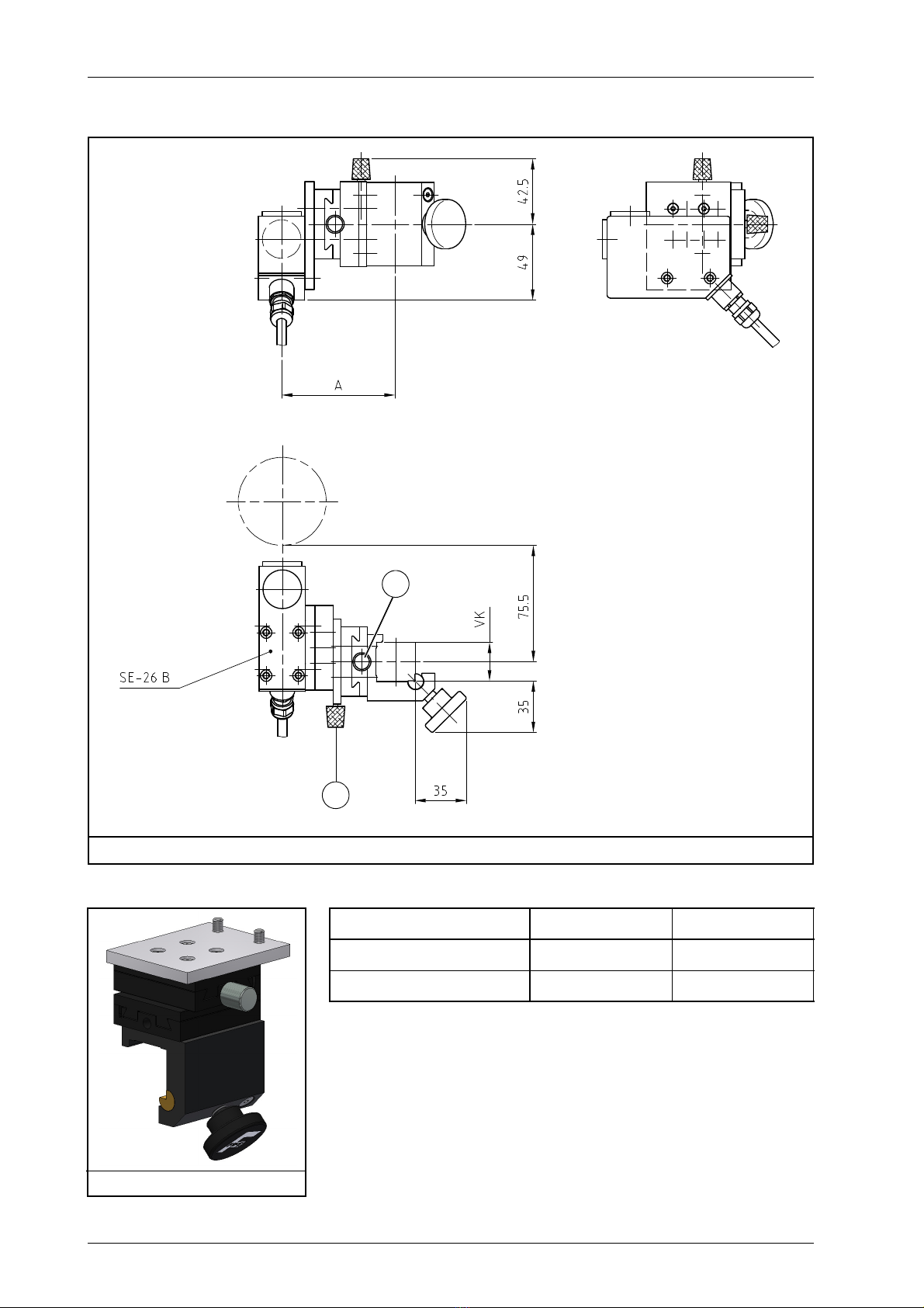
Dimensions
Mounting location –ProtectionClass:IP65
– Operating temperature: 0°C ... 50°C
– Relative humidity: 5% to 85%
–Protectfromvibrations
– Not in the vicinity of strong magnetic fields
The electronic components may be damaged.
– Not in places where there is a risk of explosions
– Distance between lens and material being scanned:
approx. 10mm
– The material web must be guided in the area where the light
spot appears (guide point) by a support rod or support roller.
A plane change is not permitted.
– Protect the lens of the sensor against extraneous light.
72.73
53.3
40.3
25.3
99.4
24
39
28
80
3
M5-6 tief/deep
18.7
58
30
21
(4.5)
28
28
43
M5-6 tief/deep
39
28
1525.3
15
24
M5-6 tief/deep
A Cable length plus connector about 300 mm
Figure 3.1: SE-26B Dimensions
A

INSTALLATION 3 - 3
SE-26Bwww.maxcess.eu MI 1085 1
Montage.fm
Mechanical fastening Holes with M5 threads are available on the housing for
mounting the sensor (
Figure 3.1
). A large variety of assembly
options are possible in connection with the various sensor
mountings.
CAUTION
Using long bolts introduces the risk of a short-circuit and
destroying the electronics that are located inside the housing.
Please note when assembling sensor that only the original M5*6
bolts or similar ones should be used.
INSTALLATION3 - 4
SE-26B www.maxcess.euMI 1085 1
Sensor bracket type MAMB
C
B Fine positioning C Fine adjustment for focus
Figure 3.2: SE-26B with sensor bracket MAMB
B
Type A VK
MAMB-25 smooth 74 25
MAMB-30 smooth 78 30
Figure 3.3: MAMB
INSTALLATION 3 - 5
SE-26Bwww.maxcess.eu MI 1085 1
Montage.fm
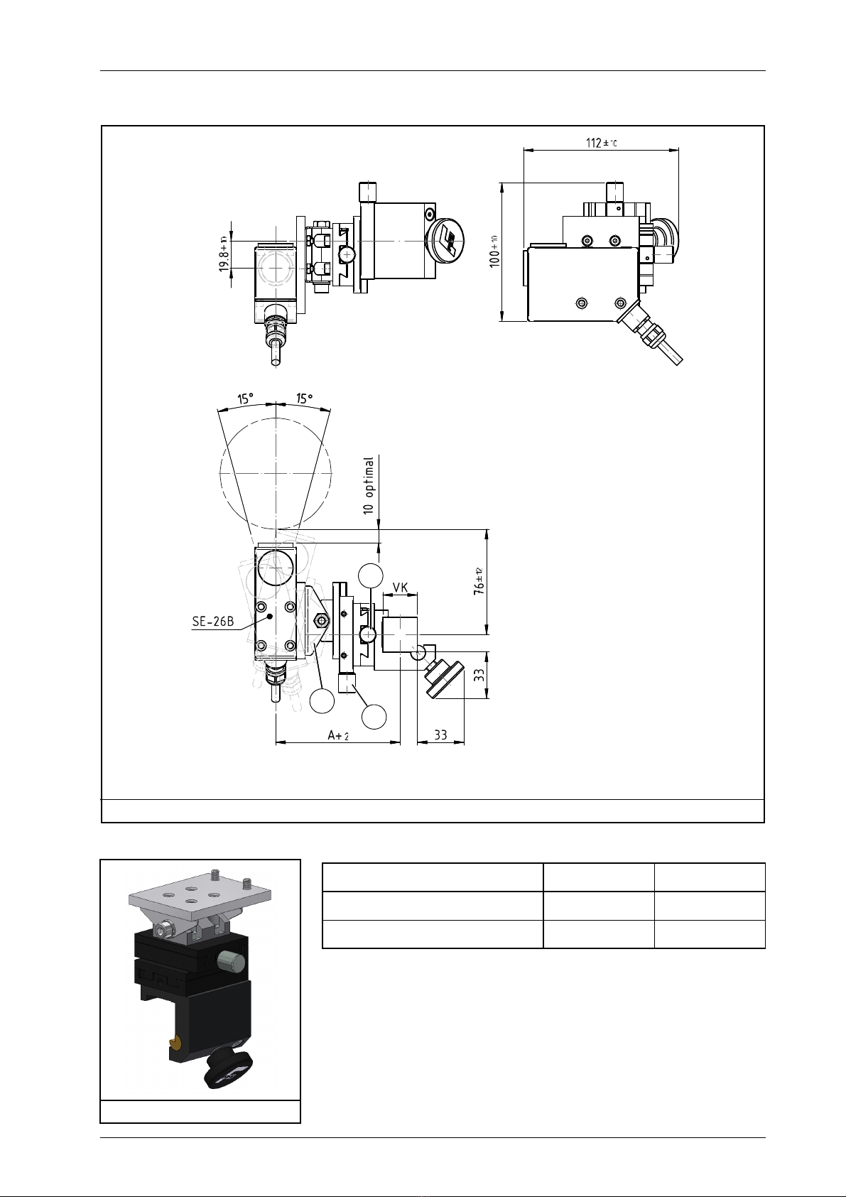
Sensor bracket type MAMB SE-26B, pivoting
B Fine positioning
C Fine adjustment for focus
D Pivot point for angle setting
Figure 3.4: SE-26B with sensor bracket MAMB, pivoting
B
D
C
Type A VK
MAMB-25 SE-26B smooth 89,5 25
MAMB-30 SE-26B smooth 93,5 30
Figure 3.5: MAMB SE-26B

INSTALLATION3 - 6
SE-26B www.maxcess.euMI 1085 1
Fine adjustment Fine positioning
This setting allows for precise positioning of the light spot on
the line/material edge being scanned.
Fine adjustment for focus
The fine adjustment of the distance between sensor and
material web must be made so that the light spot appears well
focused on the material web.
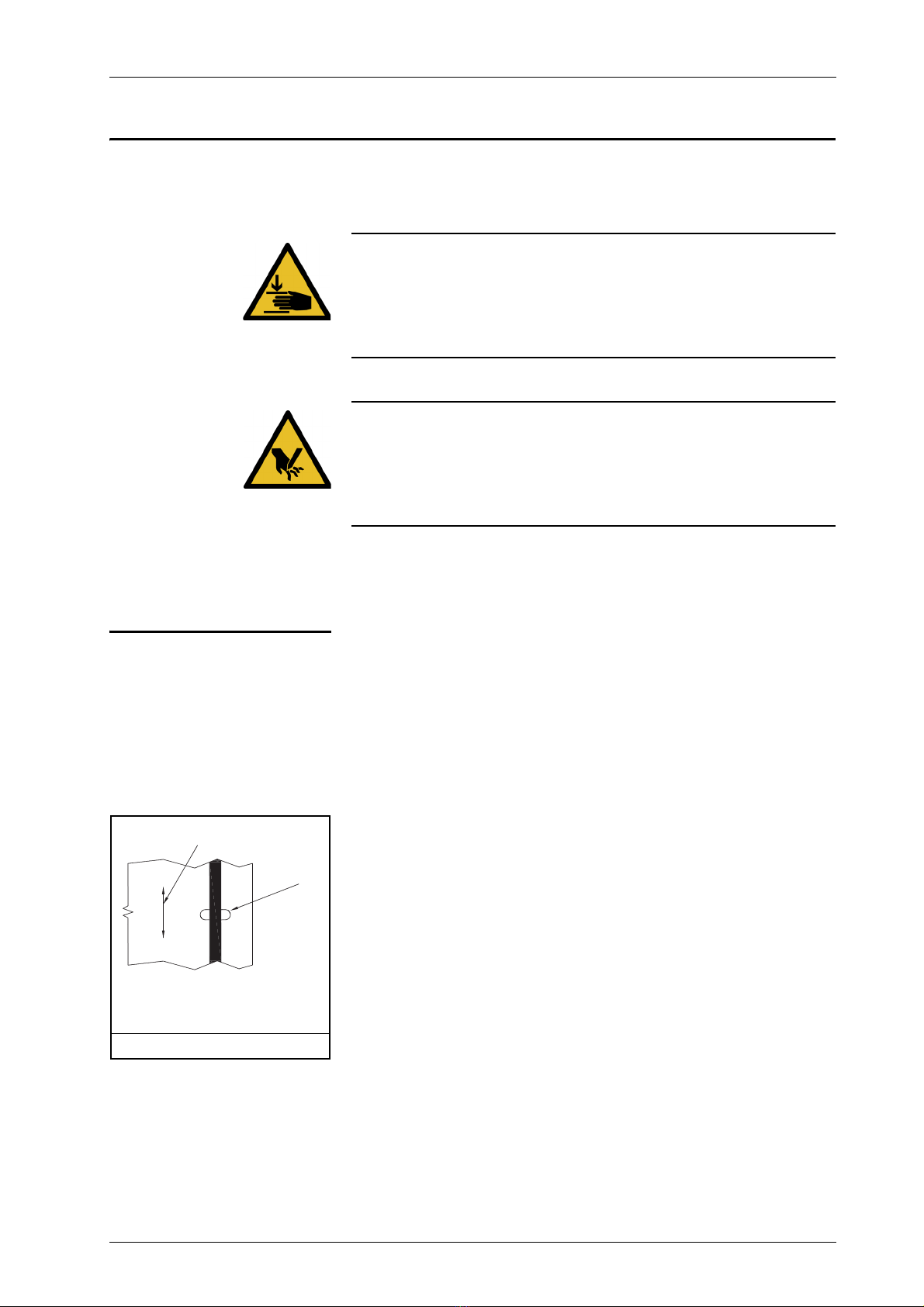
Changing the sensor
alignment ∙Unscrew the lens and cover
∙Replace the parts and screw them back in again
Note:
When screwing the parts in, make certain there is an
O-ring under each of them.
See
Figure 3.6
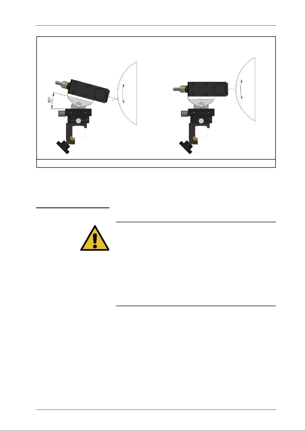
Mounting arrangement
with different materials Smooth non-reflective materials
∙Mount the sensor perpendicular to the material web so that
all of the light from the sensor is reflected into the lens
Glossy reflective materials
Examples:
Glossy laminates, metallic materials, glossy films
∙Mount the sensor at an angle of 15° from perpendicular
This will cause a portion of the sensor light to be reflected
away from the lens.
see
Figure 3.7
Figure 3.6: Sensor alignment
INSTALLATION 3 - 7
SE-26Bwww.maxcess.eu MI 1085 1
Montage.fm
Electrical connection
CAUTION
The sensor could be damaged.
Electrical connections should always be made or disconnected
on the sensor while there is no electrical power in the system.
Electrical lines must not be subjected to any mechanical
loads.
The entire wiring, for which the installer is responsible, must
meet the fundamental requirements of the relevant standard(s).
The sensor must be connected to the web guide controller
according to the system diagram in the system documentation.
Figure 3.7: SE-26B and different material types
Assembly with glossy materials Assembly with smooth materials

COMMISSIONING4 - 1
SE-26B www.maxcess.euMI 1085 1
4 COMMISSIONING
WARNING:
Before commissioning, ensure that:
Commissioning of the sensor is performed while the web is
stopped.
No one is in the danger zone of the moving parts.
WARNING:
There is a risk of crushing and cutting injuries on the web
material itself and/or due to the motion of the web.
Do not grasp moving parts (rollers, web, etc.) or anything
close to them during commissioning.
Do not touch the edges of the material web.
Commissioning Once all assembly and connection tasks have been checked and
are in proper condition, the sensor system can be placed in
operation.
Preparation of the web guide
controller The web guide controller must be prepared for use with a line
sensor.
See the
Commissioning
section in the section describing the
relevant web guide controller:
- D-MAXE with Operator Interface OI-TS (
Page 6-1
)
- D-MAXE with Operator Interface OI-N (
Page 7-1
)
- DP-20/DP-30 (
Page 8-1
)
- Fife-500 (
Page 9-1
)
-CDP-01
Sensor Calibration with Line Sensor SE-26
can
be found in the "CDP-01 Operating Manual."
Note:
When a complete system is delivered, the web guide controller
has already been mostly calibrated in the factory. The same is
not true for deliveries of individual parts or replacement parts,
however.
OPERATION 5 - 1
SE-26Bwww.maxcess.eu MI 1085 1
Betrieb.fm
5 OPERATION
WARNING:
Danger of injury by crushing
Do not place your hands on or near moving parts (rollers,
material web, etc.) during operation.
WARNING:
Danger of injury due to cutting on the edge of the material web
Do not place your hands on the edge of the (moving) material
web during operation.
Selecting suitable
references The operator must select a suitable reference (a line or an edge)
that can be found again unambiguously within the sensor field
of view on the material web.
Line The material web is guided to the center of a printed line.
– Line width between 1.3mm and 2.5mm
– Distance of at least 2.5mm on both sides of the line from
other edges or printing
– Thin lines very rich in contrast, even up to 0.25mm can be
used
– Lines can be continuous or broken
1 Direction of motion of the
material web
2Lightspot
Figure 5.1: Line
1
2
OPERATION5 - 2
SE-26B www.maxcess.euMI 1085 1
Edge The material web is guided to
– the edge of a material on a roller or support plate.
– the edge of a continuous printed sample.
– the edge of a line that is wider than 2.5mm and has a
continuous background.
Setting up references The reference is set up on the web guide controller to which the
setup menu is connected.
Preconditions – Position the sensor so that the desired reference is centered
in the sensor field of view.
– The reference must be set up while the material web is
stopped.
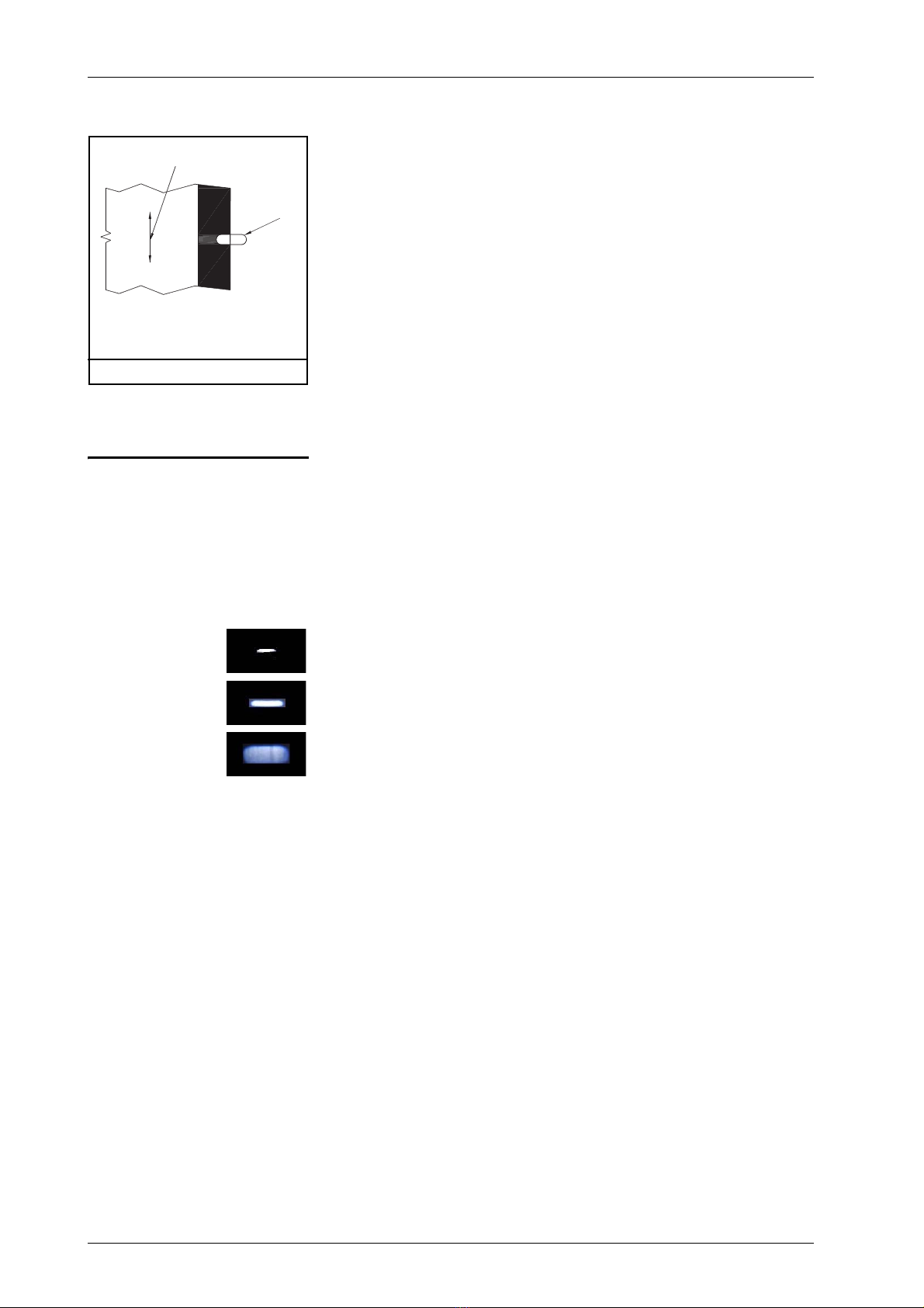
– The light spot of the line sensor must appear clearly and
unambiguously on the material web.
1 - No light spot, distance too small
2 - Light spot well focused, distance correct
3 - No light spot, distance too great
– There must be no plane change of the material web in the
area of the light spot.
Set-up Setting up the reference depends on the web guide controller in
use.
See section
Setting up a reference
in the section describing
the relevant web guide controller:
- D-MAXE with Operator Interface OI-TS (
Page 6-3
)
- D-MAXE with Operator InterfaceOI-N
(Page 7-3
)
- DP-20/DP-30 (
Page 8-3
)
- Fife-500 (
Page 9-3
)
-CDP-01
Sensor Calibration with Line Sensor SE-26
can
be found in the "CDP-01 Operating Manual."
1 Direction of motion of the
material web
2Lightspot
Figure 5.2: Edge
1
2
1
2
3

D-MAX(E) WITH OPERATOR INTERFACE OI-TS 6 - 1
SE-26Bwww.maxcess.eu MI 1085 1
Bedienung OITS.fm
6 D-MAX(E) WITH OPERATOR INTERFACE OI-TS
Preparing the controller
for use
Note:
Detailed information about sensor calibration is available in the
"D-MAX Operating Instructions". "Supplementary Operating
Instructions“ may also be available.
Precondition:
The SE-24B sensor is connected to the D-MAX(E) controller as
specified in the system diagram to X5 or X9.
Placeholder y:
These places in the menu IDs depend on the currently selected
job.
Select sensor type
∙Press the Manual key to set the "Manual" operation mode
∙Select menu 1y.5.1.1.2
Type
(Press the 6 button and hold it for 2sec. Button 5:
Hardware Button 1: Sensors Button Sensor S1 .. Sensor
S4: select the desired sensor Button 2: Type)
∙Set the
Type
to SE-26
Selecting a reference type Depending on the selected reference type, a distinction is made
in set-up for:
– a (broken) line
or
– a material edge or (broken) print edge.
D-MAX(E) WITH OPERATOR INTERFACE OI-TS6 - 2
SE-26B www.maxcess.euMI 1085 1
The properties of a reference are described in section
Selecting
suitable references, page 5-1
.
∙
Select job:
Press the 4 key until the suitable controller type for
- Line center (menu ID J or K)
or
- Material edge or print edge (menu ID L or M)
is selected
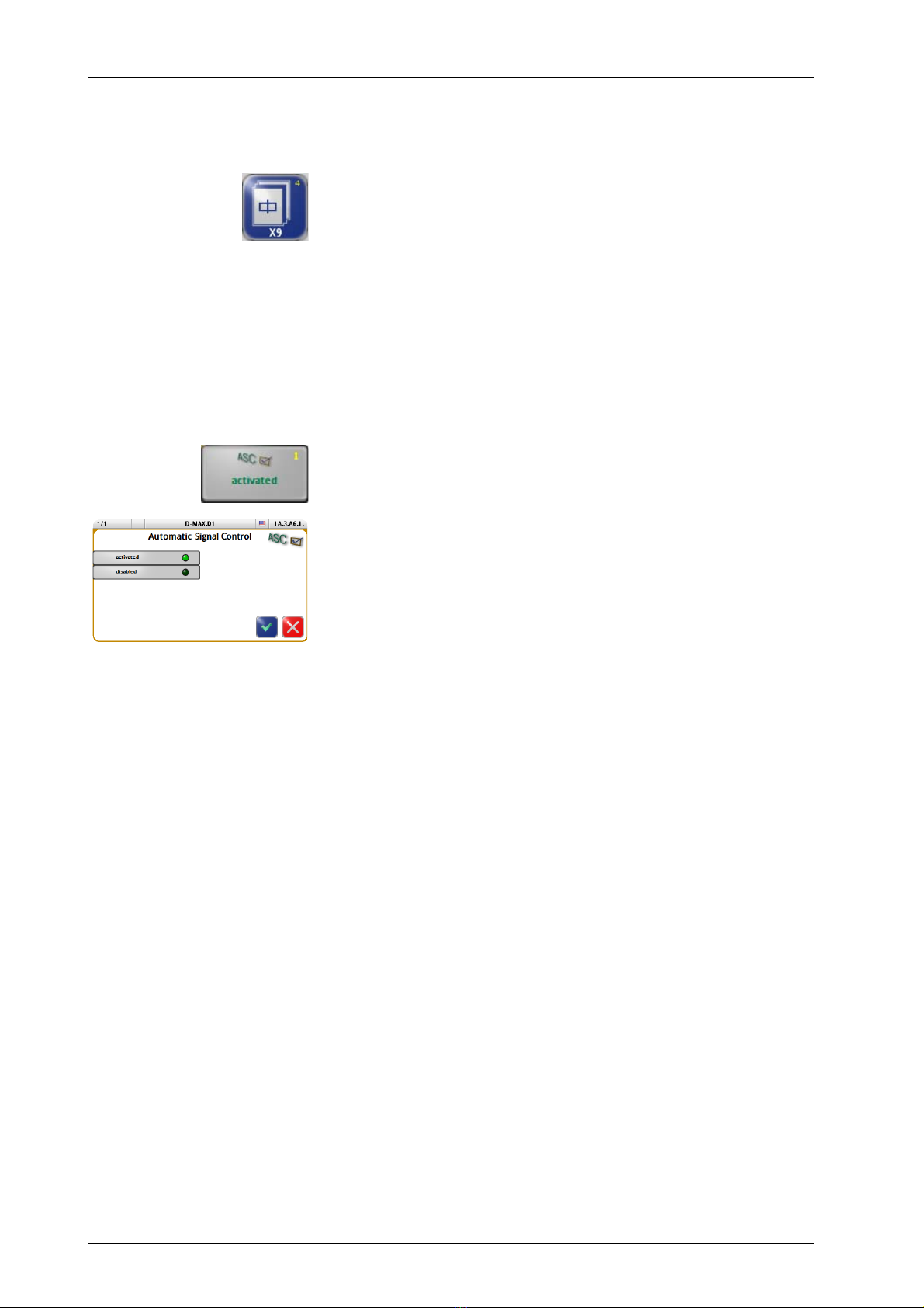
Setting up the
ASC
function
with broken line/edges
Turning on ASC blocking
∙Select menu 1y.3.y6.1
ASC Automatic Signal Control
(Button 6 Button 6: ASC Button 1: ASC)
∙Activate the
ASC
parameter
Table of contents
Other Fife Accessories manuals


