Figaro KE Series Manual

Revised 09/22 1
TECHNICAL INFORMATION FOR KE-SERIESTECHNICAL INFORMATION FOR KE-SERIES
Technical Information for Maxell Oxygen Sensor KE-Series
The Maxell Oxygen Sensor
KE-Series is a unique galvanic
cell type oxygen sensor which
provides a linear output voltage
signal relative to percent oxygen
present in a particular atmosphere.
The sensor features long life
expectancy, excellent chemical
durability, and it is not inuenced
by CO2, making it ideal for
oxygen monitoring.
Page
Introduction...............................................................................................2
Basic Information and Specications
Features...............................................................................................2
Applications.......................................................................................2
Structure and Operating Principle.................................................2
Specifications.........................................................................2
Absolute Maximum Operating and Storage Conditions............3
Dimensions.................................................................................3
Typical Sensitivity Characteristics
Sensitivity to Oxygen...........................................................................4
Response Speed..............................................................................4
InuencefromVariousGases...........................................................4
Eects of Pressure Change......................................................5
Humidity Dependency...........................................................5
Temperature Dependency..................................................................6
Reliability
Inuence of Organic Solvents.....................................................6
Life Expectancy.................................................................................6
RelationshipofExpectedLifeandO2Concentration..............6
RelationshipofExpectedLifeandStorageTemperature.........6
Long Term Stability...........................................................................7
Cautions.................................................................................................7
Limited Warranty and Limitation of Liability..........................................9
an ISO9001 company

Revised 09/22 2
TECHNICAL INFORMATION FOR KE-SERIESTECHNICAL INFORMATION FOR KE-SERIES
1. Introduction
The Maxell Oxygen Sensor KE series (KE-25 and KE-50) is
a unique galvanic cell type oxygen sensor. Its most
notable features are a long life expectancy, excellent
chemical durability, and it is not inuenced by CO2.
The KE series oxygen sensor is ideal to meet the
ever-increasing demand for oxygen monitoring in
various elds such as combustion gas monitoring, the
biochemical eld, domestic combustion appliances,
etc.
2. Basic Information and Specications
2-1 Features
* Long life (KE-25 - 5 years / KE-50 - 10 years)
* Virtually no inuence from CO2, CO, H2S, NOx, H2
* Low cost
* Operates in normal ambient temperatures
* Stable output signal
* No external power supply required for sensor
operation
* No warm-up time is required
2-2 Applications
* Biotechnology - Oxygen incubators
* Food industry - Refrigeration, greenhouses
* Safety - Air conditioners, oxygen detectors, re
detectors
2-3 Structure and operating principle
The KE series sensor is a lead-oxygen battery which
incorporates a lead anode, an oxygen cathode made of
gold, and a weak acid electrolyte. Oxygen molecules
enter the electrochemical cell through a non-porous
uorine resin membrane and are reduced at the gold
electrode with the acid electrolyte. The current
which ows between the electrodes is proportional
to the oxygen concentration in the gas mixture
being measured. The terminal voltages across the
thermistor (for temperature compensation) and
resistor are read as a signal, with the change in
output voltages representing the change in oxygen
concentration.
The following chemical reactions which take place
in KE sensors:
Cathodic reaction: O2 + 4H++ 4e-→ 2H2O
Anodic reaction: 2Pb + 2H2O → 2PbO + 4H++ 4e-
Total reaction: O2+ 2Pb →2PbO
A small volume air bubble is contained inside the sensor
body in order to compensate for internal inuence from
pressure changes. The sensor's electrolyte is primarily
composed of acetic acid with a pH of approximately 6.
The sensor's body is made of ABS resin.
Both the KE-25 and the KE-50 sensors are based on
identical design and performance principles. The
basic difference between these two models is in the
thickness of the uorine resin membrane. This affects
the diffusion speed of oxygen molecules and, as a
result, the response speed and life of the sensor. Each
model shows basically the same performance in the
various conditions described in the technical data, e.g.
inuence by other gases, pressure dependency, etc.
2-4 Specications
Table 1 (see following page) shows the specications
of the KE series oxygen sensors.
Notes:
1)
Whencalibratedatboth0%and100%ofO2,accuracy
in the range from 0-100% O2shall be within ±1% of
full scale for KE-25 and ±2% of full scale for KE-50.
2) Va = output voltage at 21% O2
V0= output voltage at 0% O2
V100 = output voltage at 100% O2
3) Va = output voltage at 25˚C
VH = output voltage at 40˚C
VL = output voltage at 5˚C
4) Sensors should be used under conditions where
the air exchange is greater than 200~300ml per
minute in order to obtain the response speed as
specied in Table 1.
2-5 Absolute maximum operating and storage conditions
Fig. 1 - Structure of KE-25/KE-50
Bottom Lid
Compensating
Resistor
Air Bubble
Electrolyte
Lead Electrode
(Anode)
Lead Wire (-)
Lead Wire (+)
Thermistor
Titanium
Lead Wire
Current
Collector
O-Ring
Inner Lid
Outer Lid
Oxygen Permeable
Membrane
Gold Electrode
(Cathode)

Revised 09/22 3
TECHNICAL INFORMATION FOR KE-SERIESTECHNICAL INFORMATION FOR KE-SERIES
The accumulated total duration of exposure to the
absolute maximum conditions listed in Table 2
should be limited to no more than 24 hours.
Cautions:
1) Beneath the lower pressure limit, sensor life may
become shorter due to excessive evaporation of the
liquid electrolyte.
Table 1 - Specications of KE-25/KE-50
Table 2 - Absolute maximum operating and storage conditions
of KE-25/KE-50
2) At pressure in excess of the upper limit, sensor
output may become unstable due to excessive air
entering through the o-ring.
3) In the range -10~-20˚C, the electrolyte will freeze
and the sensor will not function, but KE sensors
would not be damaged by freezing of the electrolyte
and will resume functioning after the electrolyte
thaws to a liquid state. Below -20˚C, the sensor may
be damaged by freezing of the electrolyte, resulting
in possible leakage of the electrolyte.
4) At temperatures in excess of the upper limit, the
ABS resin casing may deteriorate.
5) If used for a long period in an extremely dry
environment, sensor life may be shortened due to
excessive evaporation of the liquid electrolyte.
2-6 Dimensions (see Fig. 2)
Figure 2 - Dimensions of KE-25/KE-50
OXYGEN
KE-
NO.18
ø28±0.5
22.5±0.3
80±5
4±2
47.3±0.5
5
ø23.2±0.5
15
ø5
ø9
M16 x P1.0
81.5
4.5 2.5
15
Lead wire
47.3±0.5
5
ø23.2±0.5
15
ø5
ø9
ø23.2±0.5
ø9
ø9
ø16
ø16.6
50±0.5
57±0.5
Unit = mm
22.7±0.5
ø23±0.5
KE-12/KE-25/KE-50 standard version KE-25F1 (w/o flange) KE-25F3 (threaded top) KE-25F4 (O-ring top)
13
13
22.7±0.5
ø23±0.5
22.7±0.5
ø23±0.5
Item Model
KE-25 KE-50
Measurement range 0~100% O2
Accuracy (Note 1)±1% full scale ±2% full scale
Operating conditions
Atmospheric pressure 811hPa~1216hPa
Temperature 5˚~40˚C
Relative humidity 10~90%RH (no condensation)
Response time (90%) (Note 4)14±2 seconds 60±5 seconds
Initial output voltage under factory test conditions 10.0~15.5mV 47~65mV
Factory test conditions
Test gas 21% O2
Atmospheric pressure 1013hPa
Temperature 25˚±5˚C
Linearity (Va-V0)/(V100-V0)
(Note 2)0.21±0.02
Oset voltage V0≤0.5mV ≤6.0mV
Temperature
characteristics (Note 3)
VH/Va 0.91~1.09
VL/Va 0.91~1.09
Item Lower limit Upper limit
Pressure 507hPA (Note 1) 1520hPA (Note 2)
Temperature -20˚C (Note 3) 60˚C (Note 4)
Relative humidity 0%RH (Note 5) 100%RH
KE-25/KE-50 standard version
Revised 09/22 4
TECHNICAL INFORMATION FOR KE-SERIESTECHNICAL INFORMATION FOR KE-SERIES
3. Typical Sensitivity Characteristics
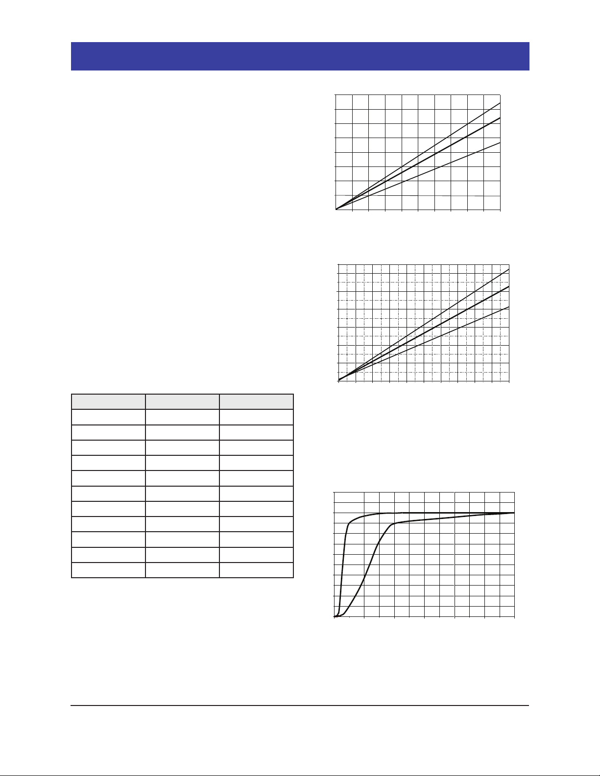
3-1 Sensitivity to oxygen
Figures 3a and 3b show the sensitivity characteristics
of the KE sensors. The Y-axis indicates the output
voltage of the sensor.
3-2 Response time
Figure 4 demonstrates the response pattern of the
sensor's output voltage. The Y-axis indicates the
output voltage ratio(%) to saturated voltage. Typical
response time to 90% of saturated response is 14
seconds for KE-25 and 60 seconds for KE-50.
3-3 Inuence of various gases
The inuence on KE sensors from various gases is
shown in Table 3. The 'interference level' shown in
the table indicates the change ratio between sensor
output in an air (20.7% O2) and gas mixture compared
to sensor output in normal air (20.7% O2). For
example, if the interference level of SO2is considered
to be 3%, that would indicate that the sensor's output
voltage in normal air (20.7% O2) would correspond
to a concentration of 21.3% O2 (20.7% x 1.03).
Fig. 3b - KE-50 sensitivity characteristics
Fig. 3a - KE-25 sensitivity characteristics
0
20
40
60
80
100
120
0 30 60 90 100 110 120
Time (sec.)
Output ratio (%)
KE-25
KE-50
Fig. 4 - Response speed of KE sensors to oxygen
Table 3 - Inuence of various gases on KE-series sensors
0
0
Oxygen concentration (%)
Output voltage (mV)
300
250
200
150
100
50
10 20 30 40 50 60 70 80 90 100
max.
min.
typ.
Gas Concentration Interference Level
Carbon monoxide 0-100% no eect
Carbon dioxide 0-100% no eect
Nitric monoxide 0-1% no eect
Nitrogen dioxide 0-1% no eect
Sulfur dioxide 0-3% 3%
Hydrogen sulde 0-3% no eect
Ammonia 0-3% 1%
Hydrogen 0-100% no eect
Hydrogen chloride 0-3% 1%
Benzene 0-100ppm 1%
Methane 0-100% no eect
Oxygen concentration (%)
Output voltage (mV)
0
70
60
50
40
30
20
10
010 20 30 40 50 60 70 80 90 100
80
max.
min.
typ.

Revised 09/22 5
TECHNICAL INFORMATION FOR KE-SERIESTECHNICAL INFORMATION FOR KE-SERIES
3-4 Effects of pressure change
The pressure dependency of KE-50 can be seen in
Figure 5. In this range of atmospheric pressure, sensor
output voltage maintains a linear relationship when
compared with atmospheric pressure. This same
tendency can be seen in all models of KE sensors.
3-5 Humidity dependency
Figure 6 displays an example of humidity dependency
for KE-50. The Y-axis shows sensor output voltage. The
sensor itself is not inuenced by humidity, but its output
voltage may show some variation to the extent that O2is
displaced by humidity, as indicated in Figure 7.
Fig. 5 - KE-50 response of output voltage to
ambient pressure changes
(at 25˚C/60%RH)
Fig. 6 - KE-50 effect of humidity on output voltage
(at 25˚C in ambient air)
Fig. 7 - Effect of humidity on O2concentration
0 20 40 60 80 100
Humidity (%RH)
O2concentration (%)
21.0
20.5
19.5
19.0
20.0
5oC
15oC
40oC
35oC
30oC
25oC
�20oC
10oC
30
45
60
75
90
800 900 1000 1100 1200 1300
Sensor output (mV)
Atmospheric pressure (hPa)
max.
min.
typ.
30
40
50
60
70
20 40 60 80
Sensor output (mV)
Humidity (%RH)
max.
min.
typ.
100
This manual suits for next models
6
Table of contents
Other Figaro Accessories manuals


