Fike Clean Agent System Instruction Manual
Design, Installation & Maintenance Manual
for
Fike Clean Agent Systems
w/ FM-200™, GCA and DOT / TC Containers
P/N 06-215 (Rev G)
Revision Date: January, 2010


REVISION HISTORY
Manual P/N: 06-215
Document Name: DESIGN, INSTALLATION, AND MAINTENANCE MANUAL
FOR ENGINEERED HFC-227ea SYSTEMS
Original Release Date..........................................................................................................................February, 2001
Revision / Description of Change Revision Date
Revision A................................................................................................................................................... April, 2002
1) Added reference to 4BW500 containers to Section 1
2) Moved details on 4BA500 containers to Appendix B
Revision B....................................................................................................................................................July, 2003
1) Add low pressure switch to Section 1 & 4
2) Add back to back 180° nozzles to Section 2
Revision C ................................................................................................................................................March, 2004
1) Changed minimum design concentration in Section 2 for Class A hazards
2) Revised sample problem in Section 3
Revision D ...................................................................................................................................................May, 2005
1) Updated 10, 20 & 35-lb container information in Section 1 and 4
Revision E...................................................................................................................................................June, 2006
1) Add notes to par 2.7.4 on page 15 and par 2.8.5 on page 22, of Design Section regarding 10 pipe dia.
limitation for back to back 180 degree nozzles
Revision F...................................................................................................................................................June, 2009
1) Added 3/8” Sch 40 & Sch 80 pipe to paragraph 4.4, Section 4
2) Changed Mounting Bracket information in Section 1 & 4
3) Removed 10 lb. Container from Manual
4) Removed Notes (Class C energized hazards) under paragraph 2.2.2 in Section 2
5) Added reference to ULC and TC to manual
6) Updated information on 1” & 2” Check Valves in Section 1 & 2
7) Reformatted Nozzle information
8) Removed reference to 4B500/4BM500 in paragraph 1.5.2, Section 1
Revision G.............................................................................................................................................January, 2010
1) Added threaded valve information to Sections 1, 2 and 4

This page intentionally left blank

TABLE OF CONTENTS
Manual P/N: 06-215 (Rev G)
INTRODUCTION............................................................................................................................................ 1 PAGE
SECTION 1 – EQUIPMENT.......................................................................................................................25 PAGES
1.1 AGENT..........................................................................................................................................................1
1.2 PERFORMANCE ..........................................................................................................................................1
1.3 PHYSICAL PROPERTIES – HFC-227ea (FM-200) .....................................................................................1
1.4 USE and LIMITATIONS................................................................................................................................2
1.4.1 Exposure........................................................................................................................................................2
1.4.2 Exposure Limits.............................................................................................................................................2
1.4.3 Toxicity...........................................................................................................................................................3
1.4.4 Noise..............................................................................................................................................................3
1.4.5 Turbulence.....................................................................................................................................................3
1.4.6 Chilling...........................................................................................................................................................3
1.4.7 Visibility..........................................................................................................................................................3
1.4.8 Pressure ........................................................................................................................................................3
1.5 AGENT STORAGE CONTAINERS..............................................................................................................4
1.5.1 Rupture Disc..................................................................................................................................................4
1.5.2 Containers w/ 1” (25mm) Valve.....................................................................................................................5
1.5.3 Containers w/ 2 ½” (65mm) Valve.................................................................................................................7
1.5.3.1 Floor Mounting Kits.................................................................................................................................8
1.5.4 Containers w/ 3” (80mm) Valve.....................................................................................................................9
1.5.4.1 Mounting Straps....................................................................................................................................10
1.6 ITEMS FURNISHED W/ CONTAINERS.....................................................................................................11
1.6.1 Nameplate ...................................................................................................................................................11
1.6.2 Siphon Tube ................................................................................................................................................11
1.6.3 Victaulic Coupling & Nipple .........................................................................................................................11
1.6.4 Pressure Gauge ..........................................................................................................................................11
1.6.5 Pressure Gauge Adapter.............................................................................................................................12
1.6.6 Agent Fill Valve............................................................................................................................................12
1.6.7 Agent Release Module (ARM).....................................................................................................................13
1.6.8 Mounting Hardware For GCA & ARM .........................................................................................................13
1.7 GAS CARTRIDGE ACTUATOR (GCA) .....................................................................................................14
1.8 CONTAINER ACCESSORIES....................................................................................................................15
1.8.1 Liquid Level Indicator (LLi) ..........................................................................................................................15
1.8.2 Low Pressure Switch...................................................................................................................................16
1.8.3 Reload Kits ..................................................................................................................................................16
1.8.3.1 Reload Kit – 1” Valve ............................................................................................................................17
1.8.3.2 Reload Kit – 2½ “ Valve ........................................................................................................................18
1.8.3.3 Reload Kit – 3” Valve ............................................................................................................................19
1.9 CONTAINER ORDERING FORMAT..........................................................................................................20

TABLE OF CONTENTS
Manual P/N: 06-215 (Rev G)
1.10 DISCHARGE NOZZLES.............................................................................................................................21
1.10.1 Pre-Engineered Discharge Nozzles............................................................................................................21
1.10.2 Engineered Discharge Nozzles...................................................................................................................22
1.10.3 Nozzle Ordering Format for Engineered Discharge Nozzles......................................................................22
1.11 CHECK VALVES ........................................................................................................................................23
1.12 CAUTION / ADVISORY SIGNS..................................................................................................................24
1.12.1 Do Not Enter Sign........................................................................................................................................24
1.12.2 Exit Sign.......................................................................................................................................................24
1.12.3 Do Not Enter Sign........................................................................................................................................24
1.12.4 System Abort Sign.......................................................................................................................................24
1.12.5 System ReleaseSign...................................................................................................................................24
1.12.6 Main/Reserve Sign......................................................................................................................................24
1.13 CONTROL SYSTEM & ACCESSORIES....................................................................................................25
1.13.1 Control Panels.............................................................................................................................................25
1.13.2 Manual Acturator.........................................................................................................................................25
SECTION 2 – SYSTEM DESIGN...............................................................................................................39 PAGES
2.1 DETERMINE HAZARD TYPE.......................................................................................................................1
2.2 DETERMINE CONCENTRATION PERCENTAGE ......................................................................................1
2.2.1 Class "A" or "C" Hazards – Automatically Activated .....................................................................................1
2.2.2 Class "A" or "C" Hazards – Manually Activated ............................................................................................1
2.2.3 Class B Flammable Liquids-Automatically or Manually Activated System ...................................................2
2.3 SAFETY RECOMMENDATIONS..................................................................................................................2
2.3.1 Normally Occupied Spaces...........................................................................................................................2
2.3.2 Normally Non-Occupied Spaces...................................................................................................................2
2.3.3 All Spaces......................................................................................................................................................2
2.4 DETERMINE AGENT QUANTITY ................................................................................................................3
2.4.1 Determine The Hazard Volume.....................................................................................................................3
2.4.2 Calculate Agent Required..............................................................................................................................3
2.4.3 Additional Considerations..............................................................................................................................6
2.4.3.1 Tee Design Factor ..................................................................................................................................6
2.4.3.2 Altitude Correction Factors .....................................................................................................................8
2.4.3.3 Determine Actual Concentration at Maximum Temperature ..................................................................8
2.4.3.4 Leakage ..................................................................................................................................................9
2.5 SYSTEM DESIGN CONCEPT ....................................................................................................................10
2.5.1 Pre-Engineered Systems Concept..............................................................................................................10
2.5.2 Engineered Systems Concept.....................................................................................................................10
2.5.3 Modular Systems.........................................................................................................................................10
2.5.4 Central Storage Systems.............................................................................................................................10

TABLE OF CONTENTS
Manual P/N: 06-215 (Rev G)
2.6 CONTAINER SELECTION..........................................................................................................................11
2.6.1 Container Size and Fill Range.....................................................................................................................11
2.6.2 Container Location(s)..................................................................................................................................12
2.6.3 Storage Temperature Limitations................................................................................................................12
2.7 NOZZLE SELECTION.................................................................................................................................13
2.7.1 System Type................................................................................................................................................13
2.7.2 Nozzle Flow Rates.......................................................................................................................................13
2.7.2.1 Engineered Nozzles..............................................................................................................................14
2.7.3 Nozzle Area Coverage ................................................................................................................................14
2.7.4 Nozzle Placement........................................................................................................................................15
2.7.4.1 Ceiling Heights Greater Than 16'-0" (4.9 m).........................................................................................16
2.7.5 Nozzle Discharge Obstructions...................................................................................................................17
2.8 PIPING NETWORK LIMITATIONS (ENGINEERED SYSTEMS)...............................................................18
2.8.1 Tee Split Ratios ...........................................................................................................................................18
2.8.1.1 Bullhead Tee.........................................................................................................................................18
2.8.1.2 Side-Thru Tee.......................................................................................................................................18
2.8.2 Maximum Elevation Differences in Pipe Runs ...........................................................................................19
2.8.3 Tee Orientation............................................................................................................................................20
2.8.4 Estimating Pipe Size (Engineered Systems)...............................................................................................21
2.8.4.1 Discharge Duration ...............................................................................................................................21
2.8.4.2 Minimum Flow Rates ............................................................................................................................21
2.8.5 Minimum Piping Distance (Engineering Systems)......................................................................................22
2.8.5.1 Distance from a Tee to an Elbow or Tee..............................................................................................22
2.8.5.2 Distance from an Elbow to a Tee..........................................................................................................22
2.8.6 Equivalent Length Values............................................................................................................................23
2.9 ENGINEERED SYSTEM DESIGN LIMITS.................................................................................................24
2.9.1 Percent of Agent In Pipe..............................................................................................................................24
2.9.2 Location of First Tee....................................................................................................................................24
2.9.3 Liquid Arrival Time.......................................................................................................................................25
2.9.4 Liquid Runout Time .....................................................................................................................................25
2.10 MANIFOLD OPTIONS (ENGINEERED SYSTEMS)...................................................................................26
2.11 PER-ENGINEERED SYSTEMS DESIGN...................................................................................................29
2.11.1 Piping Layout...............................................................................................................................................29
2.11.2 Determining Pipe Sizes...............................................................................................................................29
2.11.2.1 Single Nozzle Piping Table – 35 lb. thru 215 lb. Containers ................................................................30
2.11.2.2 Two Nozzle Piping Table – 60 lb. thru 375 lb. Containers....................................................................31
2.11.2.3 Four Nozzle Piping Table – 60 lb. thru 375 lb. Containers...................................................................32

TABLE OF CONTENTS
Manual P/N: 06-215 (Rev G)
2.11.3 Determining the Total Pressure Drop (TPD)...............................................................................................33
2.11.3.1 Piping Layout Diagram......................................................................................................................... 33
2.11.3.2 Total Pressure Drop (TDP) Calculation................................................................................................34
2.11.3.2-A Single Nozzle Factors Table ..........................................................................................................34
2.11.3.2-B Two Nozzle Factors Table..............................................................................................................36
2.11.3.2-C Four Nozzle Factors Table.............................................................................................................38
SECTION 3 – SAMPLE PROBLEM...........................................................................................................17 PAGES
3.1 DETERMINE HAZARD VOLUME.................................................................................................................1
3.2 CALCULATE AGENT REQUIRED.............................................................................................................. 2
3.2.1 Determine Concentration At Maximum Temperature................................................................................... 2
3.3 ESTABLISH SYSTEM CONCEPT ...............................................................................................................3
3.3.1 Container Selection.......................................................................................................................................3
3.3.2 Nozzles Required..........................................................................................................................................3
3.4 LAYOUT PIPING NETWORK.......................................................................................................................5
3.5 SAMPLE FLOW CALCULATION.................................................................................................................7
SECTION 4 – SYSTEM INSTALLATION ..................................................................................................21 PAGES
4.1 AGENT STORAGE CONTAINERS..............................................................................................................1
4.1.1 Mounting Details for Vertical / Horizontal Containers....................................................................................1
4.1.1.1 Mounting Details 20 lb. & 35 lb. (8L & 15L) Container ...........................................................................2
4.1.1.2 Mounting Details 60 lb. (27 L) Container................................................................................................3
4.1.2 Mounting Details for Inverted (Spherical) Containers ...................................................................................4
4.1.2.1 Mounting Details 125 lb. (51 L) Container..............................................................................................4
4.1.2.2 Mounting Details 215 lb. (90 L) Container..............................................................................................5
4.1.3 Mounting Details for Vertical (Upright) Containers........................................................................................6
4.2 DISCHARGE PIPING CONNECTIONS........................................................................................................7
4.2.1 1" (25mm) Valve Connections.......................................................................................................................7
4.2.2 2-1/2" (65mm) Valve Connections.................................................................................................................7
4.2.3 3" (80mm) Valve Connections.......................................................................................................................8
4.3 MANIFOLDS………………………………………………………………….......................................................8
4.3.1 1" NPT Check Valve Installation..................................................................................................................10
4.3.2 2" NPT Check Valve Installation..................................................................................................................10
4.3.3 3" NPT Check Valve Installation..................................................................................................................10
4.4 PIPING AND FITTING MATERIALS ..........................................................................................................11
4.4.1 Pipe Size Changes......................................................................................................................................12
4.4.1.1 Pipe Size Change at a Tee...................................................................................................................12
4.4.1.2 Pipe Size Change at an Elbow .............................................................................................................12
4.4.1.3 Pipe Size Change at a Coupling...........................................................................................................12
4.4.2 Installing Main Discharge Piping.................................................................................................................12

TABLE OF CONTENTS
Manual P/N: 06-215 (Rev G)
4.5 NOZZLE INSTALLATION...........................................................................................................................13
4.5.1 360°Nozzles ...............................................................................................................................................14
4.5.2 180°Nozzles ...............................................................................................................................................14
4.5.3 Nozzle Set Screw Installation......................................................................................................................14
4.6 GAS CARTRIDGE ACTUATOR (GCA) / AGENT RELEASE MODULE (ARM) .......................................15
4.6.1 2-1/2" (65 mm) Valve (Inverted Container) GCA Installation......................................................................15
4.6.2 1" & 3" (25 mm & 80 mm) Valve GCA Installation.......................................................................................16
4.7 CONTAINER ELECTRICAL CONNECTIONS ...........................................................................................17
4.7.1 Gas Cartridge Actuator (GCA) Safety Recommendations..........................................................................18
4.7.2 Gas Cartridge Actuator (GCA) Installation Procedure ................................................................................19
4.8 LOW PRESSURE SWITCH........................................................................................................................20
4.8.1 Low Pressure Switch Wiring........................................................................................................................21
SECTION 5 – FINAL SYSTEM CHECKOUT...............................................................................................2 PAGES
5.1 HAZARD AREA CHECK ……………...........................................................................................................1
5.1.1 Area Configuration.........................................................................................................................................1
5.1.2 Area Leakage ……........................................................................................................................................1
5.1.3 Enclosure Integrity - Door Fan Testing..........................................................................................................1
5.2 CONTAINERS ………………........................................................................................................................2
5.3 DISCHARGE PIPING ………........................................................................................................................2
5.4 NOZZLES......................................................................................................................................................2
5.5 AUXILIARY FUNCTIONS …….....................................................................................................................2
SECTION 6 – SYSTEM MAINTENANCE....................................................................................................3 PAGES
6.1 DISCHARGE PIPING....................................................................................................................................1
6.2 DISCHARGE NOZZLES...............................................................................................................................1
6.3 AGENT STORAGE CONTAINERS..............................................................................................................1
6.4 GAS CARTRIDGE ACTUATORS.................................................................................................................2
6.5 CONTAINER TEST AND INSPECTION.......................................................................................................2
6.6 PRESSURE GAUGE & LOW PRESSURE SWITCH MAINTENANCE .......................................................3
6.6.1 Replacing a Pressure Gauge or Low Pressure Switch.................................................................................3
6.6.2 Adding a Low Pressure Switch......................................................................................................................3
APPENDIX – MATERIAL SAFETY DATA SHEETS.................................................................................13 PAGES
Material Safety Data Sheet – HFC-227ea Agent .............................................................................. 8 Pages
Material Safety Data Sheet – Gas Cartridge Actuator (GCA)........................................................... 3 Pages
4BA Container Information................................................................................................................ 2 Pages

This page intentionally left blank

INTRODUCTION
UL / ULC Ex4623 Fike Clean Agent System w/ FM-200™ Page 1 of 1
FM 3010715 Manual P/N: 06-215 (Rev G) Revision Date: January, 2010
Fike is pleased to provide a “Design, Installation and Maintenance Manual” for our Clean Agent Fire Suppression
systems w/ FM-200™ agent. This document has been revised to incorporate the latest design requirements
found in NFPA Standard 2001, as well as the most up-to-date information available for our products.
This manual has been provided for those individuals that are responsible for the design, installation, and/or
maintenance of Fike Clean Agent Fire Suppression systems. Others such as architects, engineers, sales and
marketing personnel, etc. will find the information herein useful as well.
Fike offers two concepts of system design that are described within the following chapters.
1. Pre-Engineered Systems – These are simple “boilerplate” systems that operate within a pre-
determined set of criteria as tested and approved by Underwriters Laboratories Inc. These systems
do not require the designer to perform a complicated set of hydraulic flow calculations and they are
intended to provide a fast, easy means of designing systems.
2. Engineered Systems – These are the more complicated, elaborate systems that operate within a less
restrictive set of criteria as tested and approved by Underwriters Laboratories Inc. These systems
are designed within the basic parameters outlined in this manual, and their performance is evaluated
with the assistance of the Fike Flow Calculation Program.
Tests have shown that the Fike Flow Calculation Program can accurately determine the expected
performance of the Clean Agent Fire Suppression system when it is discharged. This provides the
system designer with the maximum degree of flexibility possible as it pertains to flow imbalance, tee
splits, piping configurations, etc.
Fike Clean Agent Fire Suppression systems must be installed and maintained in accordance with the limitations
established NFPA Standard no. 2001, Clean Agent Extinguishing Systems, as well as the limitations set forth by
Underwriters Laboratories Inc. The information contained within this manual defines these limitations in detail.
Enough information is incorporated into this manual to allow those responsible for designing Fike Clean Agent
Fire Suppression systems to properly do so, and for the parties responsible for verifying the system design to
determine if the design parameters have in deed been met.
The data contained within this manual is provided for informational purposes only. Fike believes this data to be
accurate; however, all dimensions are approximate and this document is presented without any guarantee or
warranty whatsoever.
Any questions concerning the information presented in this manual should be addressed to:
Fike Corporation
P.O. Box 610
Blue Springs, MO 64013
Phone: (816) 229-3405
Fax: (816) 229-5082
Webpage: www.fike.com

This page intentionally left blank

SECTION 1 – EQUIPMENT
UL / ULC Ex4623 Fike Clean Agent System w/ FM-200™ Page 1 of 25
FM 3010715 Manual P/N: 06-215 (Rev G) Revision Date: January, 2010
This section covers the hardware utilized by Fike Clean Agent Fire Suppression Systems, including the optional
items that are available. All of the information contained herein is believed to be accurate and up-to-date.
However, it should be noted that all dimensions shown are approximate and Fike reserves the right to make
adjustments as necessary.
1.1 AGENT
The extinguishing agent used in Fike Suppression Systems is Heptafluoropropane – more commonly known by its
ASHRAE designation: HFC-227ea. HFC-227ea is a colorless, odorless, liquefied compressed gas. (See the
Physical Properties Table below.) It is stored as a liquid, but dispensed into the hazard as a colorless,
electrically-nonconductive, gaseous vapor due to its relatively low boiling point. HFC-227ea has been tested and
verified to be safe for use in occupied spaces when used as specified in the U.S. EPA Significant New Alternative
Policy (SNAP) rules. Tests have proven that exposure to HFC-227ea is safe and effective in extinguishing fires at
low concentrations; most of which are well below the EPA’s maximum exposure levels. HFC- 227ea is approved
for use in occupied areas up to a 10.5% concentration by volume with mandated egress time of five (5) minutes.
1.2 PERFORMANCE
HFC-227ea’s mechanism of extinguishing fires is considered active. Its primary action is through physically
cooling the fire at the molecular level. HFC-227ea belongs to the same class of agents used in refrigeration and
as such, is an efficient heat transfer agent. HFC-227ea removes the thermal energy from the fire to the extent
where the combustion reaction cannot sustain itself. Additionally, there is a chemical action that provides a
secondary means of extinguishing the fire. Trace amounts of free radicals are released into the fire – thereby
inhibiting the chain reaction of combustion. HFC-227ea does not significantly reduce oxygen levels and is safe
for use in occupied spaces in accordance with the U.S. EPA guidelines. HFC-227ea can be removed from the
protected space by simple means of ventilation after discharge.
1.3 PHYSICAL PROPERTIES OF HFC-227ea (FM-200™)
Chemical Name 1,1,1,2,3,3,3-Heptafluoropropane
Chemical Formula CF CHFCF
CAS No. 431-89-0
Molecular Wt. 107.03
Boiling Point, 1 atm, oC (oF) -15.9
oF (3.9)
Freezing Point, oC (oF) -133 (-204)
Flammable Limits nonflammable
Critical Temperature, oC (oF) 101.6 (214.9)
Critical Pressure, kPa (psia) 2930.6 (424.7)
Critical Density, kg/m3(lb/ft3) 621 (38.77)
Liquid Density @ 25oC (77oF), kg/m3(lb/ft3) 1386 (86.53)
Vapor Density @ 25 oC (77oF) and 1atm, kg/m3(lb/ft3) 7.148 (0.4462)
Specific Heat, Liquid (Cp) @ 25oC (77oF), kJ/kg-oC (Btu/lboF) 1.247 (0.2979)
Specific Heat, Vapor (Cp) @ 25oC (77oF), kJ/kg-oC (Btu/lboF) and 1 ATM 0.8136 (0.1945)
Vapor Pressure, Saturated @ 25oC (77oF), kPa (psia) 453.3 (65.7)
Heat of Vaporization @ B.P., kJ/kg (Btu/lb) 132.6 (56.7)
Thermal Conductivity, Liquid @ 25oC (77oF),W/m-oC (Btu/hr-ftoF) 0.0533 (0.0308)
Thermal Conductivity, Vapor @ 25oC (77oF),W/m-oC (Btu/hr-ftoF) 0.0127 (0.0073)
Viscosity, Liquid (lb/ft-hr) @ @ 25oC (77oF), cP (lb/ft-hr) 0.2442 (0.5907)
Relative dielectric strength @ 1atm, 25oC (N2 =1) 2.00
Solubility of Water in HFC-227ea @ 20oC (68oC ), ppm 600
Ozone Depletion Potential 0.0 (CFC-11 = 1)
Global Warming Potential, GWP (100 yr. ITH. For CO2, GWP = 1) 2900
Atmospheric Lifetime, years 36.5
TSCA Inventory Status Reported, Included
European List of New Chemical Substances EINECS, Listed (207-079-2)
SNAP Status Listed
Inhalation Exposure Limit TLV Not Established DuPont AEL = 1000
ppm 8 hr & 12 hr TWA

SECTION 1 – EQUIPMENT
Page 2 of 25 Fike Clean Agent System w/ FM-200™ UL / ULC Ex4623
Revision Date: January, 2010 Manual P/N: 06-215 (Rev G) FM 3010715
1.4 USE AND LIMITATIONS
Fike HFC-227ea Systems must be designed and installed in accordance with the requirements outlined in this
manual, and in accordance with the requirements of the Standard for Clean Agent Extinguishing Systems, NFPA
2001, latest edition. HFC-227ea systems are primarily used to protect hazards that are enclosed; this provides a
means to establish and maintain an effective extinguishing concentration. Typical hazards that can be protected
include the following.
Electrical and electronic hazards
Telecommunications facilities
Storage Rooms – Flammable liquids and gases
High value assets, where the associated down-time would be costly
HFC-227ea systems shall NOT be used on fires involving the following materials.
Chemicals or mixtures of chemicals which are capable of rapid oxidation in the absence of air. Examples
include Cellulose Nitrate and Gunpowder.
Reactive metals such as Lithium, Sodium, Potassium, Magnesium, Titanium, Zirconium, Uranium, and
Plutonium
Metal hydrides such as Sodium Hydride and Lithium Aluminum Hydride
Chemicals capable of undergoing auto thermal decomposition. Examples include Organic Peroxides and
Hydrazine.
1.4.1 EXPOSURE
Although HFC-227ea is considered to be non-toxic, the EPA has established the guidelines controlling the
amount (concentration) of agent provided for the protected area. Based on PBPK modeling, the EPA allows
HFC-227ea for use where people are normally present (normally occupied spaces) up to concentration of 10.5%
by volume with exposure limited to 5 minutes or less.
WARNING: The discharge of clean agent systems to extinguish a fire can result in potential hazard to
personnel from the natural form of the clean agent or from the products of combustion that result
from exposure of the agent to the fire or hot surfaces. Unnecessary exposure of personnel either
to the natural agent or to the products of decomposition shall be avoided.. The requirement for
pre-discharge alarms and time delays are intended to prevent unnecessary exposure to humans
where their presence is not critical to the operation of the area being protected. Suitable
safeguards shall be provided to ensure prompt evacuation of (and prevent entry into) protected
areas after discharge.
1.4.2 EXPOSURE LIMITS
HFC-227ea systems provided for Normally Occupied Spaces can be designed for concentrations above to the
NOAEL level of 9% by volume, given that means be provided to limit exposure to design concentrations shown in
Table 1.4 that correspond to a maximum permitted human exposure time of five (5) minutes.
HFC-227ea
Concentration ppm Human Exposure
Time (minutes)
9.0% 90,000 5.00
9.5% 95,000 5.00
10.0% 100,000 5.00
10.5% 105,000 5.00
11.0% 110,000 1.13
11.5% 115,000 0.60
12.0% 120,000 0.49
TABLE 1.4

SECTION 1 – EQUIPMENT
UL / ULC Ex4623 Fike Clean Agent System w/ FM-200™ Page 3 of 25
FM 3010715 Manual P/N: 06-215 (Rev G) Revision Date: January, 2010
HFC-227ea systems provided for Normally Non-Occupied Spaces can be designed for concentrations in
excess of the LOAEL concentration of 10.5%. Where a possibility exists for personnel to be exposed, means
shall be provided to limit exposure times in accordance with the above table. In the absence of the information
needed to fulfill the conditions listed above, the following provisions shall apply.
Where egress takes longer than 30 seconds but less than 1 minute, the HFC-227ea system shall not
be designed for a concentration exceeding the LOAEL of 10.5% by volume.
Where egress takes less than 30 seconds, the HFC-227ea system can be designed for a
concentration that exceeds the LOAEL of 10.5% by volume.
1.4.3 TOXICITY
With a database in excess of 70 toxicity tests, HFC-227ea has been extensively tested and approved by
institutions and agencies around the world. The LC50 toxicity rating for HFC-227ea is greater than 800,000 ppm.
When you consider that most HFC-227ea systems are designed for concentrations providing 105,000 ppm or
less, it is evident that HFC- 227ea is safe to use.
HFC-227ea will decompose to form halogen acids when exposed to extremely high temperatures. The formation
of these acids is minimized by using fast-acting Fike detection and control systems, and proper system design
and installation of the piping system to deliver the agent quickly. The generation of by-products from the HFC-
227ea discharge will be minimal when properly applied.
1.4.4 NOISE
The high-pressure discharge from the nozzle(s) of a system can cause noise that is loud enough to be startling,
but ordinarily insufficient to cause traumatic injury.
1.4.5 TURBULENCE
The high velocity discharge from the nozzle(s) can be sufficient enough to dislodge substantial objects located
directly in the discharge path. Enough general turbulence may be created within the enclosure to move
unsecured paper and light objects.
1.4.6 1.4.6 CHILLING
Direct contact with the vaporizing agent being discharged from the nozzle(s) will have a chilling effect on objects
and can cause cryogenic burns to the skin. The liquid phase vaporizes rapidly when mixed with air, thus limiting
the hazard to the immediate vicinity of the discharge nozzle.
1.4.7 VISIBILITY
Although HFC-227ea is odorless, discharging the agent into a humid atmosphere may cause a reduction in
visibility for a brief period of time due to condensation of water vapor normally present in the room atmosphere.
1.4.8 PRESSURE
The normal operating pressure of a Fike HFC-227ea clean agent extinguishing system unit is 360 psig @ 70oF
(24.8 bar @21oC). This is accomplished by adding a charge of nitrogen to the HFC-227ea agent. Since these
are pressurized vessels, care must be observed when handling, filling and transporting storage containers. The
anti-recoil devices (baffle plugs or baffle plates) MUST be in place whenever the charged container is removed
from the piping network.
SECTION 1 – EQUIPMENT
Page 4 of 25 Fike Clean Agent System w/ FM-200™ UL / ULC Ex4623
Revision Date: January, 2010 Manual P/N: 06-215 (Rev G) FM 3010715
1.5 AGENT STORAGE CONTAINERS
The Agent Storage Container is a steel pressure vessel designed to hold the HFC-227ea under pressure until it is
discharged. All Fike HFC-227ea Containers are suitable for use at storage temperatures of +32oF to +130oF (0oC
to 54.4oC). Each container is manufactured in strict accordance with Department of Transportation / Transport
Canada (DOT / TC) regulations and undergoes extensive pressure and leak testing before shipment to the field.
All Fike HFC-227ea Containers are shipped from the factory fitted with an anti-recoil device installed in the
discharge valve outlet – in accordance with DOT / TC requirements. The anti-recoil device ensures the contents
of the pressurized container will be released in a slow, controlled, rate of discharge if the valve is opened during
the shipping and handling process. HFC-227ea Containers are filled with agent within the allowable range of 40
lbs/ft3to 70 lbs./ft3(640 kg/m3to 1121 kg/m3) of container volume in accordance with DOT / TC requirements. All
containers are filled in 1 lb. (0.5 kg) increments to the user-specified level defined for each container. Each HFC-
227ea container is super-pressurized with dry nitrogen to a working pressure of 360 psig at 70oF (24.8 bar at
21oC) after filling. Fike HFC-227ea Containers are available in twelve different sizes (capacities). Each container
includes a discharge outlet valve, fill valve, pressure gauge, mounting bracket or mounting strap(s), agent release
module, and provisions for the accessories available for that particular container size and/or style.
The Discharge Outlet Valve is a rupture disc (metal diaphram), pressure operated device that allows the agent to
be released from the container and into the protected space via the associated piping network and nozzle(s). The
Discharge Outlet Valve can be either welded or threaded to the Agent Storage Container (except for the 125i &
215i containers available with welded valves only).
Activation of the Discharge Outlet Valve is accomplished by one of two methods.
Standard operation of the valve is accomplished by a Gas Cartridge Actuator (GCA) that produces
the pressure wave (energy) necessary to open the valve. The GCA is an electrically operated device
that is activated by a signal from the control panel or the optional manual actuator device.
If the contents of the container are subjected to temperatures exceeding 160oF (71oC), the pressure
associated with the thermal expansion of the agent will be sufficient to open the valve automatically.
NOTE: The Discharge Valve also fulfills the pressure relief valve requirements in accordance with DOT
regulations.
NOTE: Containers manufactured by Fike for use with HFC-227ea to DOT 4BA requirements can be found in
Appendix B.
1.5.1 RUPTURE DISC
The Rupture Disc is the heart of the Fike HFC-227ea Discharge Outlet Valve. Each is manufactured to exacting
tolerances and standards by Fike to ensure their reliability and performance. The Rupture Disc is a pre-scored
metal membrane formed into a domed shape and scored with four pressure-relief lines across the domed surface
at right angles to each other. When the pressure in the container rises to the pre-determined level, the rupture
disc will open along the score lines – thus allowing the contents to be released into the piping network. The four
segments of the rupture disc “fold back” during discharge to produce the minimum amount of flow restriction
possible.
SECTION 1 – EQUIPMENT
UL / ULC Ex4623 Fike Clean Agent System w/ FM-200™ Page 5 of 25
FM 3010715 Manual P/N: 06-215 (Rev G) Revision Date: January, 2010
1.5.2 CONTAINERS – 1” (25 mm) VALVE
Containers are available in the following sizes (capacities): 20, 35, 60, and 100 lb. (8.5, 15, 27, and 44 L). Each
of these containers utilize a 1” NPT (25 mm) discharge outlet valve, consisting of a 1” (25 mm) rupture disc
assembly operated by a Gas Cartridge Actuator (GCA).
All containers are designed and fabricated in accordance with DOT 4BW500 requirements. Containers are also
available with dual markings that meet the requirement of both DOT and TC; the associated ratings for these
containers are 4BW500/4BWM500.
For ordering information, refer to Section 1.9 of this section.
Each container is supplied with a 1” NPT (25 mm) anti-recoil device (pipe plug) installed in the adapter nut (outlet)
of the discharge valve. The pipe plug supplied has a 1/8” (4 mm) hole drilled through the plug to allow the
container pressure to vent safely to atmosphere in the event that the discharge valve is activated prior to
installation.
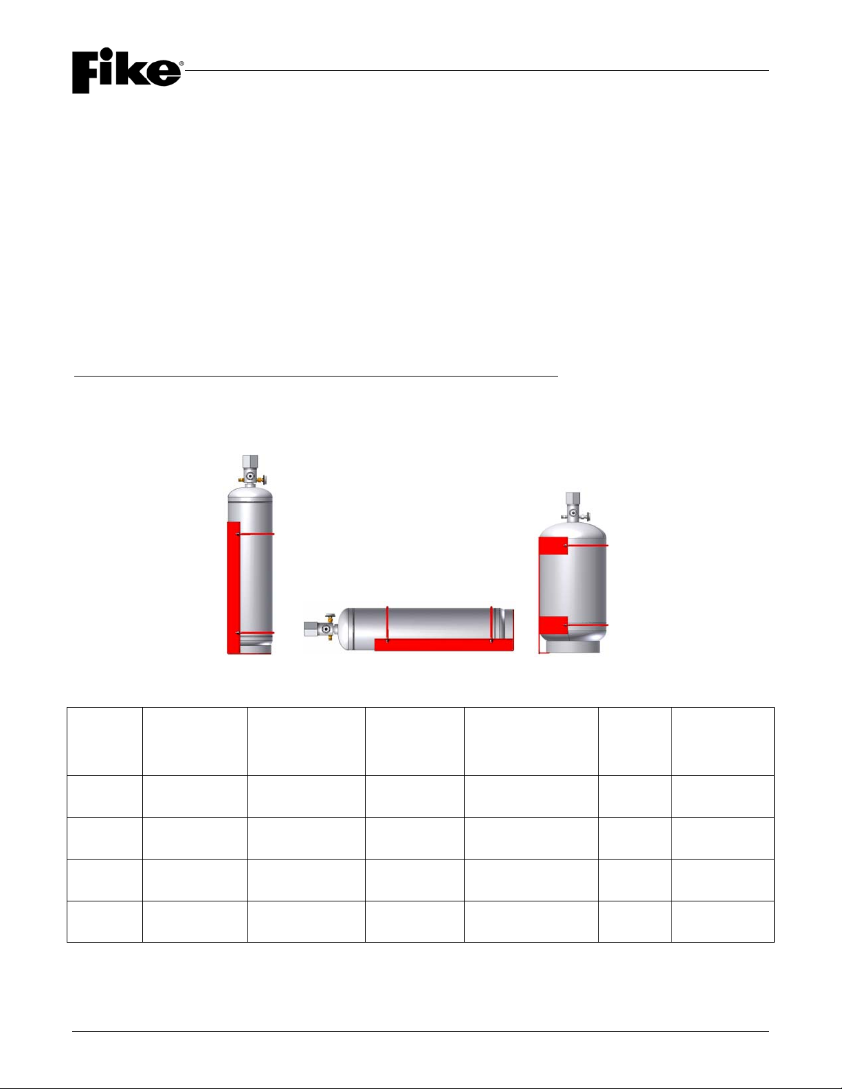
The 20, 35 and 60 lb. (8.5, 15 and 27 L) containers can be mounted in either the horizontal or upright (valve up)
positions.
The 100 lb. (44 L) container MUST be installed in the upright (valve up) position. Horizontal mounting of the 100
lb. (44 L) container is not allowed. Mounting Brackets are supplied with each container, and each must be
anchored to an appropriate load-bearing structure.
NOTE: The 20 lb. (8.5 L) container (P/N 70-098) is approved for ENGINEERED Systems only.
CONTAINER DATA TABLES
Container
Size
Container
Part Number
(w/ Welded Valve)
Container
Part Number
(w/ Threaded Valve)
Fill Range
lbs. (kg) Mounting
Position Valve
Size Approx.
Tare Weight
20 lb.
(8.5 L)
70-098 70-098T
12.0 – 21.0
(5.5 – 9.5) Upright - Horizontal 1” NPT
(25 mm) 21.0 lbs.
(9.5 kg)
35 lb.
(15 L)
70-089 70-089T
22.0 – 38.0
(10.0 – 17.0) Upright - Horizontal 1” NPT
(25 mm) 31.0 lbs.
(14.1 kg)
60 lb.
(27 L)
70-152 70-152T
39.0 – 68.0
(18.0 – 30.5) Upright - Horizontal 1” NPT
(25 mm) 43.0 lbs.
(19.5 kg)
100 lb.
(44 L)
70-153 70-153T
63.0 – 108.0
(28.5 – 48.5) Upright (Valve Up) 1” NPT
(25 mm) 61.0 lbs.
(27.7 kg)
SECTION 1 – EQUIPMENT
Page 6 of 25 Fike Clean Agent System w/ FM-200™ UL / ULC Ex4623
Revision Date: January, 2010 Manual P/N: 06-215 (Rev G) FM 3010715
NOTE: All dimensions shown are approximate
Dimension “B”
Container Size Dimension “A” Container w/ Welded Valve Container w/ Threaded Valve
20 lb. (8.5 L) 7” (178 mm) 21-1/2” (546 mm) 23-1/2” (597 mm)
35 lb. (15 L) 7” (178 mm) 32-1/2” (826 mm) 35” (889 mm)
60 lb. (27 L) 10-3/4” (273 mm) 28” (711 mm) 29-1/4” (743 mm)
100 lb. (44 L) 10-3/4” (273 mm) 38-3/4” (984 mm) 40-3/4” (1035 mm)
“B”
“A”
SECTION 1 – EQUIPMENT
UL / ULC Ex4623 Fike Clean Agent System w/ FM-200™ Page 7 of 25
FM 3010715 Manual P/N: 06-215 (Rev G) Revision Date: January, 2010
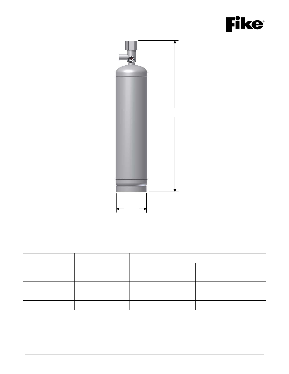
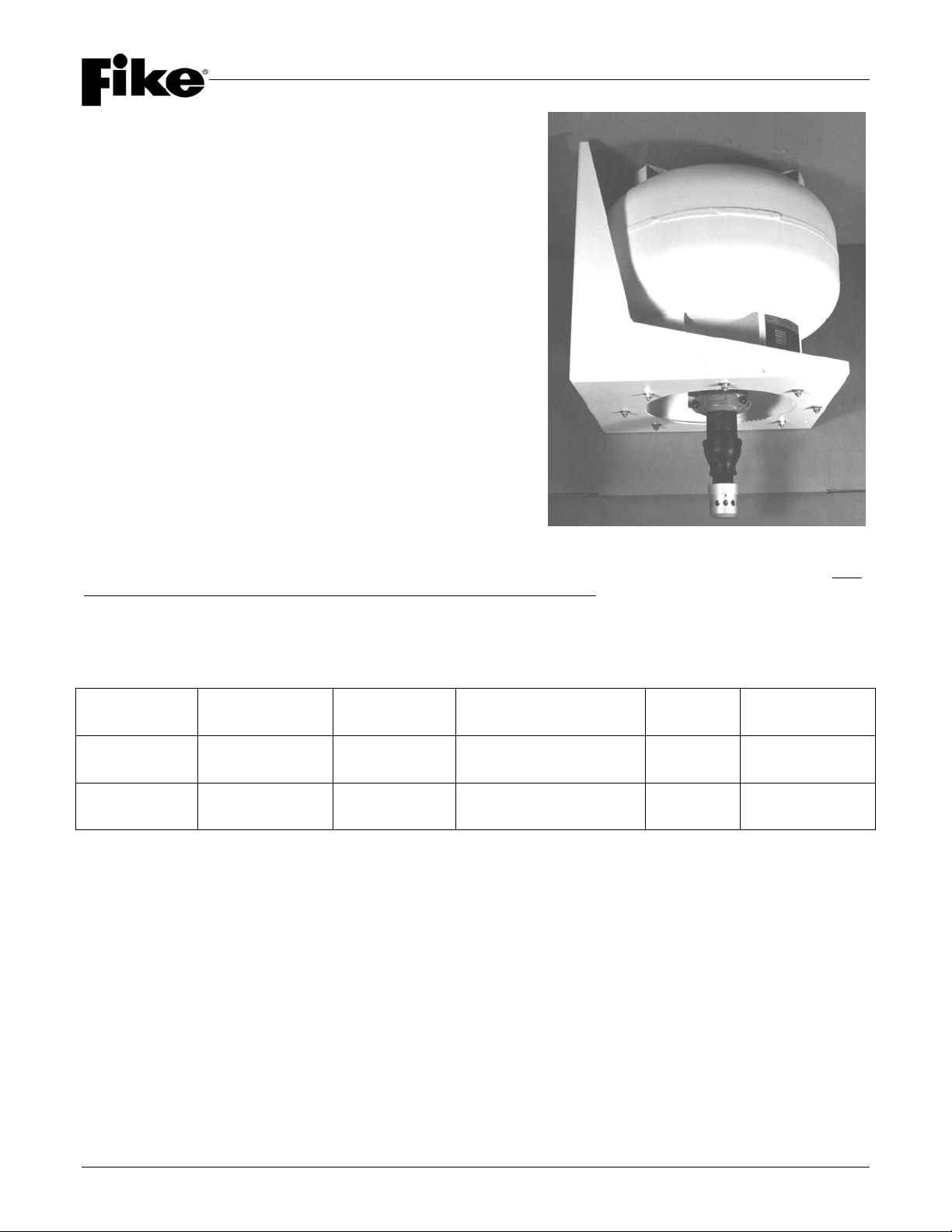
1.5.3 CONTAINERS w/ 2 ½” (65 mm) VALVE
Inverted (Spherical) HFC-227ea Containers are available in the
following sizes (capacities): 125 and 215 lb. (51 and 90 L). Both
of these containers utilize 2-1/2” NPT (65 mm) discharge outlet
valves, consisting of 2-1/2” (65 mm) rupture discs operated by
Gas Cartridge Actuators.
All containers are designed and fabricated in accordance with
DOT requirements. The associated rating is 4BA500.
Containers are also available with dual markings that meet the
requirement of both DOT and TC; the associated ratings for
these containers are 4BA500/4BAM500.
For ordering information, refer to Section 1.9 of this section.
Each container is supplied with 2-1/2” (65 mm) anti-recoil devices
consisting of a steel baffle plate with a 3/8” dia. (10 mm) hole
drilled through the plate. This allows the container pressure to
safely vent to atmosphere if the discharge valve is activated prior
to installation. The baffle plate is installed in the Grooved
Coupling attached to the discharge outlet valve.
The 125 and 215 lb. (51 and 90 L) Inverted Containers MUST be
installed in the valve down (inverted) position. Mounting Brackets
are supplied with each container, and each must be anchored to
an appropriate load-bearing structure.
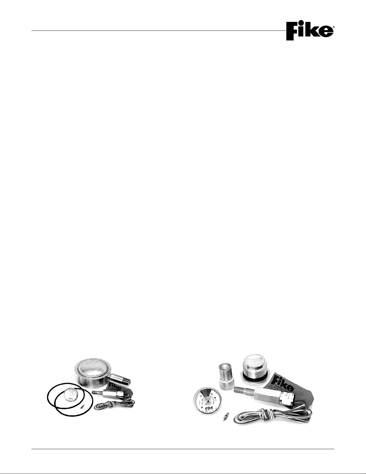
Both containers are equipped with a Liquid Level Indicator Boss to install the optional Liquid Level Indicator. This
device must be installed prior to filling the container with HFC-227ea agent.
CONTAINER DATA TABLES
Container
Size
Container
Part Number Fill Range
(lbs.) Mounting
Position Valve
Size Approx.
Tare Weight
125 lb.
(51 L)
70-041 73 – 126
(33.5 – 57)
Inverted
(Valve Down)
2-1/2” NPT
(65 mm) 141.0 lbs.
(64.0 kg)
215 lb.
(90 L)
70-077 128 – 223
(58.5–101.0)
Inverted
(Valve Down)
2-1/2” NPT
(65 mm) 200.0 lbs.
(90.7 kg)
SECTION 1 – EQUIPMENT
Page 8 of 25 Fike Clean Agent System w/ FM-200™ UL / ULC Ex4623
Revision Date: January, 2010 Manual P/N: 06-215 (Rev G) FM 3010715
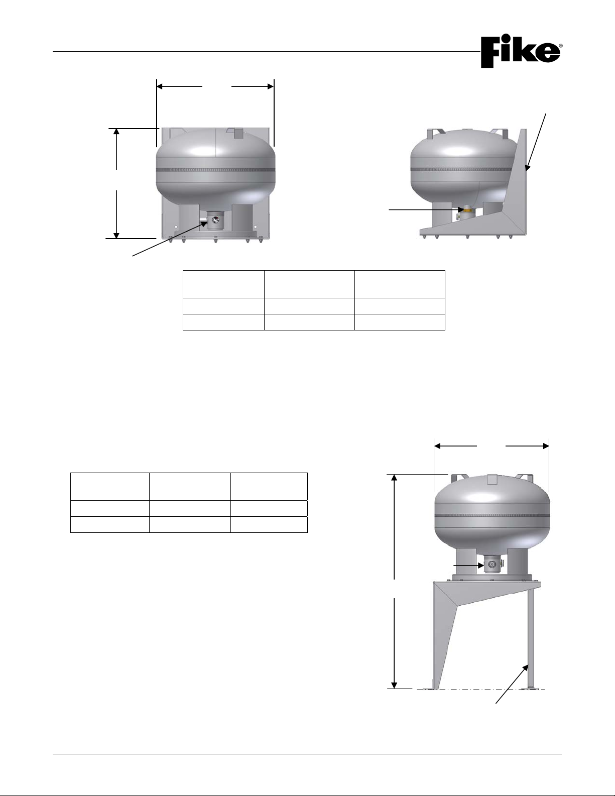
*All dimensions shown are approximate
1.5.3.1 FLOOR MOUNTING KIT
An optional Floor Mounting Kit is available for the Inverted Containers that allows the container to be mounted
near the floor. Two kits are available as follows:
P/N 70-1197 Mounting Bracket – 125 lb. (51 L) Container
P/N 70-1198 Mounting Bracket – 215 lb. (90 L) Container
All dimensions shown are approximate
Container
Size Dim. “A”
inch (mm) Dim. “B”
inch (mm)
125 lb. (51 L) 20” (508 mm) 20-1/4” (515 mm)
215 lb. (90 L) 24” (610 mm) 23-3/4” (605 mm)
Container
Size Dim. “A”
inch (mm) Dim. “B”
inch (mm)
125 lb. (51 L) 22-1/2” (572) 39-3/4” (1010)
215 lb. (90 L) 26-1/4” (667) 45-3/4” (1162)
Li
q
uid Level Boss
Mounting Bracket
“A”
“B”
Outlet Valve
“B”
“A”
Mounting Surface 1 ½” (40mm) Pipe
Cut to 18 3/8” (46.67mm) Long
Outlet Valve
Table of contents
Popular Laboratory Equipment manuals by other brands


Ametek
Ametek Reichert XCEL 255 user guide

Teledyne Cetac Technologies
Teledyne Cetac Technologies ASX-500 Alignment procedure

Bio-Optica
Bio-Optica PF200 User and service manual

Mind Peak
Mind Peak WaveRider operating manual

Liquid Instruments
Liquid Instruments Moku:Go quick start guide

Phcbi
Phcbi MLS-3020U operating instructions