Fike FAAST XT 68-302 User manual
FK-600-000 1 I56-4223-001
SPECIFICATIONS
Electrical Characteristics
External Supply Voltage 18 – 30 VDC
Average SLC Operating Current 300 µA
Power Reset 1 sec
Relay Contact Ratings 3.0A @ 30VDC, 0.5A @125VAC
Environmental Ratings
Operating Temperature 32F (0C) to 100F (38C)
Sampled Air Temperature -4F (-20C) to 140F (60C)
Humidity 10 to 95% non-condensing
IP Rating IP30
68-302 FAAST
Fire Alarm Aspiration Sensing Technology®
INSTALLATION AND MAINTENANCE INSTRUCTIONS
I56-4223-001
The purpose of this document is to provide practical information for mount-
ing and connecting to FAAST XT. For full product information, which includes
installation guidelines, instructions for safe use, and warranty and safety
information, refer to the FAAST XT Comprehensive User Guide available at
systemsensor.com/68-302userguide or by scanning the QR code.
ITEMS INCLUDED WITH UNIT
• FAAST XT (68-302) unit
• Mounting bracket and hardware
• Installation and Maintenance Instructions
• USB interface cable
• PipeIQ software, comprehensive manual, and other helpful documents
may be downloaded at systemsensor.com/faast
CONNECTING TO FAAST XT
FAAST XT requires a configuration download from PipeIQ in order to initialize.
This connection can be achieved using either the USB port located on the front of
the device, or the Ethernet port located inside the wiring cabinet.
CONNECTING TO FAAST XT VIA USB
NOTE: In order to connect your computer to the FAAST XT using a USB con-
nection, a USB driver must first be installed. The driver installation occurs
during the installation of PipeIQ version 2.0 or later. Once the driver is in-
stalled, connect to the device using the following steps.
1. Launch PipeIQ.
2. Create a new project and select FAAST XT device, or open an existing project
3. Expand the tree view in the left side navigation pane to reveal the device
4. Right click on the device and select ‘Connect Device’
5. Select USB, The USB combo box should already be populated with FAAST
XT (Com Port Number).
6. Select Read only/Administrator(requires password – default is ‘password’)
mode Click Connect.
CONNECTING TO FAAST XT VIA ETHERNET
Default Device IP Configuration
IP Address: 192.168.1.10
Subnet Mask: 255.255.255.0
Default Gateway: 192.168.1.1
Primary DNS: 0.0.0.0
Secondary DNS: 0.0.0.0
CONFIGURE YOUR PC
Your PC will need to be sitting on the same local area network as the FAAST XT device
in order to establish communication. Change your PC’s IP address to 192.168.1.15 by:
1. Accessing your network setting in your PC’s control panel
2. Open ‘Local Area Connection’ settings and select ‘Properties’
3. Select ‘Internet Protocol Version 4 (TCP/IPv4) and then select ‘Properties’
4. Select ‘Use the following UP address and enter 192.168.1.15. If the
subnet mask does not automatically populate, enter 255.255.255.0
into the subnet mask field.
5. Hit OK and close out of the network menus.
(Important Note: Before changing your PC’s IP address, be sure to take note of
whether your IP is currently dynamically set, or is a static IP address. If your PC
is assigned a static IP address, make note of the IP address and subnet mask so
that you can change back to the proper settings after the FAAST XT is configured.)
CONNECT USING PIPEIQ
1. Launch PipeIQ. (PipeIQ may be downloaded from systemsensor.com/faast)
2. Create and save a new project, or open an existing project
3. Expand the tree view in the left side navigation pane to reveal the device
4. Right click on the device and select ‘Connect Device’
5. Change the User field to ‘Administrator’ and enter the password – the
default password is ‘password’ – then hit ‘Connect’
6. Upon connection, a green check will appear next to the device in the
navigation tree
INSTALLATION
This equipment must be installed in accordance with all local and national
codes and regulations.
PIPE INSTALLATION
The pipe layout is designed using the PipeIQ software package. Refer to the
Comprehensive Instruction Manual to design the pipe network. All pipe must
be installed in accordance with local and national codes and regulations. The
pipe network should be complete before proceeding with the physical and
electrical system installation.
PHYSICAL UNIT INSTALLATION
WARNING
Make sure that there are no pipes or electrical wires within the wall before
drilling any mounting holes
SECURING THE MOUNTING BRACKET
The typical mounting location for the FAAST XT unit is on the wall. The unit
is mounted to the wall using the enclosed mounting plate. Figure 1 shows the
wall mounting plate. For easier access to the FAAST XT unit, it is preferred to
position the mounting plate in an easily accessible location.
1. Place the mounting bracket on the wall in the desired location and use
it as a template to locate the necessary mounting holes.
2. Mark the hole locations and remove the bracket. It is recommended to
secure the bracket using the 4 outer mounting holes.
3. Using a drill and the proper size bit for your mounting hardware, drill
the necessary holes.
4. Use appropriate fasteners to accommodate the mounting surface and
FAAST XT device weight.
5. Secure the bracket to the wall.
704 S. 10th Street
Blue Springs, MO 64015
Phone: 816.229.3405; Fax: 816.228.9277
www.fike.com
R

FIGURE 1: WALL MOUNTING PLATE
FIGURE 2: MOUNTING SLOTS FOR MOUNTING STUDS
CONNECTING THE AIR SAMPLING PIPE
ATTENTION
Detailed pipe network information and best practices can be found in the
Pipe Installation Guide, available for download at systemsensor.com/faast
The input and output ports are designed to accept nominal one inch pipe
(25mm). The input and output ports are tapered to provide fast, easy, pushfit
connection of the sampling pipe to the unit. Perform the following procedure
to connect the air sampling pipe to the unit.
1. Square off and de-burr the end of the sampling pipe. Ensure that the
pipe is free from any particles that might interfere with the pipe con-
nection.
2. Remove the input plug from the input port being used (either the top
or bottom of the unit).
3. Inset the air sampling pipe into the port, ensuring a snug fit. DO NOT
glue these pipes.
EXHAUST PIPE
The device should always be exhausted in to the space that it is monitoring.
There are some circumstances where it may be necessary to connect a pipe to
the exhaust port to divert the exhaust away from the location of the unit. Add-
ing as little as 2ft of exhaust pipe also acts as a muffler for the fan – ensuring
quieter operation. The output ports are tapered the same as the input ports, to
provide fast, easy, push-fit connection of an exhaust pipe to the unit. Perform
the following procedure to connect the exhaust pipe to the unit.
1. Square off and de-burr the end of the sampling pipe. Ensure that the
pipe is free from any particles that might interfere with the pipe con-
nection.
2. Remove the input plug from the input port being used (either the top
or bottom of the unit).
3. Inset the air sampling pipe into the port, ensuring a snug fit. DO NOT
glue these pipes.
WIRING
WARNING
Before working on the FAAST XT system, notify all required authorities that
the system will be temporarily out of service. Make sure all power is removed
from the system before opening the unit. All wiring must be in accordance
with local codes.
POWER CABLES
Use the power ratings of the unit to determine the required wire sizes for each
connection. Use the power ratings of the connected products to determine the
wire size.
CONDUIT USAGE
If electrical conduit is used for system wiring, terminate the conduits at the
cable entry ports on the top or bottom of the unit, using the appropriate con-
duit connectors.
1. Run all wiring, both power and alarm, through the conduit and into
the left side of the unit enclosure, as seen in Figure 3.
2. Attach the appropriate wires to the supplied Euro connector. Follow
appropriate local codes and electrical standards for all cabling.
3. Plug the appropriate connector into the mating connector on the unit.
ASP115-00
ASP116-00
FK-600-000 2 I56-4223-001
MOUNTING THE DETECTOR TO THE BRACKET
Once the mounting plate is attached, the unit is ready to be mounted on to the
plate. Perform the following procedure to mount the unit.
1. Before installing the unit onto the bracket, remove the appropriate
conduit caps from the top or bottom left side of the unit to match the
orientation of the wiring. See Figure 4 for location of the wiring access
plugs.
2. Line up the unit with the four mounting clips and the mounting studs
on the left side.
3. Push the unit down onto the mounting clips and secure it with the
supplied washer and nut on the mounting stud protruding through the
mounting slot shown in Figure 2.
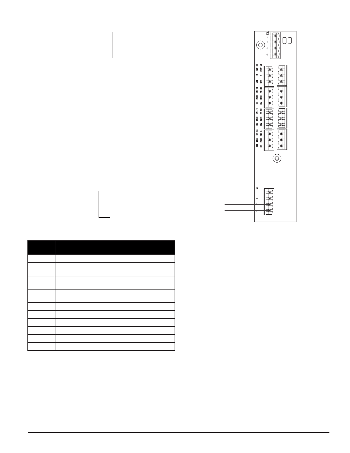
TERMINAL
BLOCK
T1 External Power – Powers Aspirating Smoke Detector
T2 SLC power – Powers SLC Interface Circuit. Isolated from
External Power
T3 RS 485 Rx
Rx and Tx can be wired in a half duplex configuration
T4 RS 485 Tx
Rx and Tx can be wired in a half duplex configuration
T5 Alert Relay – Maintains state on loss of power
T6 Action1 Relay – Maintains state on loss of power
T7 Action2 Relay – Maintains state on loss of power
T8 Fire1 Relay – Maintains state on loss of power
T9 Fire2 Relay – Maintains state on loss of power
T10 Fault Relay – Maintains state on loss of power
CABLING REQUIREMENTS
The FAAST XT system provides a series of Euro style pluggable terminals,
located behind the left side door of the unit. Refer to Table 1 for the proper
electrical connections to the unit. Refer to Table 2 for a typical connection for
monitoring the FAAST XT system at a Fire Alarm Control Panel (FACP).
TABLE 1. TERMINAL DESIGNATIONS SYSTEM POWERING
The following procedure describes how to initially power up the FAAST XT system.
1. Unplug the unit’s power connector to the unit before turning on the
power.
2. Turn on the power.
3. Check the voltage at the connector. Make sure it is within the required
voltage range.
4. If the voltage is within the proper range, reconnect the power connec-
tor to the unit. Do not connect the SLC at this point in order to enable
configuration.
5. Connect a computer, with PipeIQ installed, to the unit using either the
USB connection on the front of the device, or the Ethernet port located
in the left side wiring door. (See the ‘Connecting to FAAST XT’ for
detailed connection instructions.)
6. Use the PipeIQ software to set up the unit configuration required for
the particular application.
7. The PC may now be disconnected unless a permanent networked con-
nection is desired.
8. Connect to SLC
9. Verify the system fan starts up and air begins to flow out of the ex-
haust port. The user interface will provide the device status.
10. The device will establish an airflow baseline during the first five min-
utes of operation. After five minutes, the airflow level display will
provide the true measured airflow status. The device will give visual
indication of the baselining period on the LCD screen.
FK-600-000 3 I56-4223-001
FIGURE 3. POWER AND ALARM CONNECTION BLOCK
To Next SLC Device –
From FACP or Previous Device –
From FACP or Previous Device +
To Next SLC Device +
SLC
Connection
To Next Device +
24V External
Power
From Power Supply or Previous Device +
From Power Supply or Previous Device –
To Next Device –
ASP114-02

This device complies with part 15 of the FCC Rules. Operation is subject to the following two conditions: (1) This device may not cause harmful interference, and (2) this device must
accept any interference received, including interference that may cause undesired operation.
NOTE: This equipment has been tested and found to comply with the limits for a Class B digital device, pursuant to Part 15 of the FCC Rules. These limits are designed to provide
reasonable protection against harmful interference in a residential installation. This equipment generates, uses and can radiate radio frequency energy and, if not installed and used
in accordance with the instructions, may cause harmful interference to radio communications. However, there is no guarantee that interference will not occur in a particular installa-
tion. If this equipment does cause harmful interference to radio or television reception, which can be determined by turning the equipment off and on, the user is encouraged to try
to correct the interference by one or more of the following measures:
– Reorient or relocate the receiving antenna.
– Increase the separation between the equipment and receiver.
– Connect the equipment into an outlet on a circuit different from that to which the receiver is connected.
– Consult the dealer or an experienced radio/TV technician for help.
This Class B digital apparatus complies with Canadian ICES-003.
FCC STATEMENT
Fike Industries warrants its enclosed smoke detector to be free from defects in materials
and workmanship under normal use and service for a period of three years from date
of manufacture. Fike Industries makes no other express warranty for this smoke detec-
tor. No agent, representative, dealer, or employee of the Company has the authority to
increase or alter the obligations or limitations of this Warranty. The Company’s obligation
of this Warranty shall be limited to the repair or replacement of any part of the smoke
detector which is found to be defective in materials or workmanship under normal use
and service during the three year period commencing with the date of manufacture. After
contacting your local Fike Industries representative for issuing a Return Authorization
number (RA #__________) and arrange for return return of the defective units. Please
WARRANTY
include a note describing the malfunction and suspected cause of failure. The Company
shall not be obligated to repair or replace units which are found to be defective because
of damage, unreasonable use, modifications, or alterations occurring after the date of
manufacture. In no case shall the Company be liable for any consequential or incidental
damages for breach of this or any other Warranty, expressed or implied whatsoever, even
if the loss or damage is caused by the Company’s negligence or fault. Some states do not
allow the exclusion or limitation of incidental or consequential damages, so the above
limitation or exclusion may not apply to you. This Warranty gives you specific legal
rights, and you may also have other rights which vary from state to state.
This aspiration detector does not produce any hazardous laser radiation and is certified
as a Class 1 laser product under the U.S. Department of Health and Human Services
(DHHS) Radiation Performance Standard according to the Radiation Control for Health
and Safety Act of 1968. Any radiation emitted inside the smoke detector is completely
within the protective housings and external covers.
The laser beam cannot escape from the detector during any phase of operation.
The Center of Devices and Radiological Health (CDRH) of the U. S. Food and Drug
Administration implemented regulations for laser products on August 2, 1976. These
regulations apply to laser products manufactured after August 1, 1976. Compliance is
mandatory for products marketed in the United States.
LASER SAFETY INFORMATION
FK-600-000 4 I56-4223-001
©Fike 2015
Other Fike Measuring Instrument manuals

Popular Measuring Instrument manuals by other brands

LORD
LORD MicroStrain 3DM-CV5-10 Protocol manual

LaserLiner
LaserLiner AirMonitor PURE manual

Elcometer
Elcometer 204 operating instructions

aquilar
aquilar AquiTron AT-WFM Installation & operation instructions

Schmidt
Schmidt MZ-422 Series instruction manual

CID Bio-Science
CID Bio-Science CI-600 instruction manual


