aquilar AquiTron AT-WFM Installation instructions

AT-WFM
Water Flow Monitor
AquiTron
INSTALLATION
& OPERATION
INSTRUCTIONS

AT-WFM
Water Flow Monitor
LEAK DETECTION SOLUTIONS
Unit 30, Lawson Hunt Industrial Park,
Broadbridge Heath, Horsham, West Sussex,
RH12 3JR
+44 (0) 1403 216100
www.aquilar.co.uk
Table of contents
A. General Information
B. Product Information
C. Fitting The Module
D. Wiring
E. Plumbing Installation
F. Helpful Hints
G. Maintenance
H. Connection
1. Power & Battery Connection
2. Volt Free Relay Connections
3. External Trigger Input
4. Water Meter Connection
5. Solenoid Valve Connection
6. Pulse Output Connection
I. Home Screen
J. Setting The AT-WFM
K. Menu Screen
1. Controller Info
2. Installer Info
3. Manual Override
4. Event History
L. Setup (For Authorised Users Only)
1. Date and Time
2. Protection Level Mode
a. Volume Per
b. Timed
c. Crosscheck
3. Protection Level Time
4. Meters
5. Pulse Rate
6. Valves
7. Change Installer Info
8. Factory Reset
M. Event Log Messages

THE AT-WFM IS SUITABLE FOR INTERNAL USE
ONLY
POWER SUPPLY
100/240Vac, 50/60Hz, 0.15A
POWER CONSUMPTION
5 Watts Maximum
RELAYS
Number: 1 volt-free relay contact
Type: SPDT
Rating: 3 A at 250Vac/24 Vdc
TEMPERATURE
Operating: 5°C to 85°C
ENCLOSURE
White ABS. 177 mm x 114 mm x 65 mm (L x H x D)
TOUCHSCREEN
Resistive 4.3 inch TFT. Resolution: 480 x 272 pixels. Screen
size: 95 x 54 mm.
INSTALLATION ITEMS
(NOT SUPPLIED)
• Wall fasteners for surface mounting (four
screws)
TOOLS REQUIRED
• Drill or hole punch for electrical /
conduit entries
• Phillips (cross-head) screwdriver
• Flat-head screwdriver
TYPES OF WATER METER
To ensure compatibility with the AT-WFM it is strongly
recommended to use the Aquilar range of water meters. Third
party meters must be capable of supplying a dedicated volt free
pulse for volumes of 1/10/100 litre(s).
PULSE OUTPUT
Two channel
TYPES OF VALVE
Compatible with AquiTron AT-V-XX, AT-BV-XX, AT-VP-XX, AT-V-B-XX
valve ranges.
MAXIMUM OPERATING PRESSURE*
16 Bar
MINIMUM FLOW RATES*
AT-WFM will detect any ow rate greater than 0.15m3/h.
*AT-V-XX Flanged Buttery Valve and AT-BV-XX Ball Valve require
additional equipment: AT-RU1 Relay Unit
Please read the instructions carefully before attempting to install and connect the AT-WFM unit.
AT-WFM
Water Flow Monitor
A. GENERAL INFORMATION
The AquiTron AT-WFM water monitoring system that has been specically designed to help achieve the requirements of BREEAM 2018
(BRE Environmental Assessment Method). The AT- WFM system will allow designers, M&E contractors and developers to achieve the one
of the two WAT 03 Credits available to reduce the impact of water leaks that may otherwise go undetected. (To obtain the second available
WAT 03 credit Please see our product AT-OFC). The AT-WFM system is designed to monitor water owing through a pulse water meter. If
the volume of water exceeds the pre-set limit (customer adjustable) the system will alert the customer and, if an optional valve is tted,
can isolate the mains water, therefore limiting the amount of water lost to a leak and subsequent damage.
B. PRODUCT INFORMATION
LEAK DETECTION SOLUTIONS
1
Unit 30, Lawson Hunt Industrial Park,
Broadbridge Heath, Horsham, West Sussex,
RH12 3JR
+44 (0) 1403 216100
www.aquilar.co.uk
*When using Aquilar supplied water meters or valves only.
Actual rates dependent on model used. Please see relevant data
sheets.
STORAGE
Keep the module in a dry place prior to
installation to avoid possible damage to
internal components.

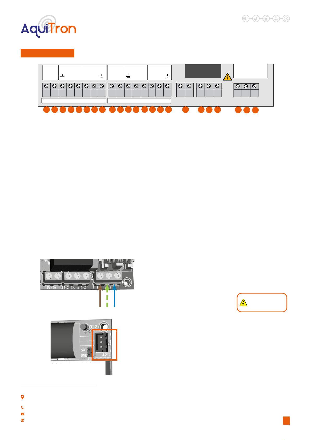
CHANNEL 1 CHANNEL 2
SOL 1 SOL 2METER 1 IN METER 2 INPULSE 1 OUT PULSE 2 OUT
+ - + -+ -+ -+ -
+ -
12
3 4 5
6
7
8
9
10
LEAK DETECTION SOLUTIONS
1. Channel 1 terminals
2. Channel 2 terminals
3. External Trigger Input
terminals
4. Volt Free Relay terminals
5. Mains power in terminals
6. Battery Connector
7. Power LED
8. Back-up battery
9. Serial Connector
10. Buzzer
2
Unit 30, Lawson Hunt Industrial Park,
Broadbridge Heath, Horsham, West Sussex,
RH12 3JR
+44 (0) 1403 216100
www.aquilar.co.uk
MAXIMUM PULSE CIRCUIT LENGTH
500 metres maximum. For circuit lengths (over 50m) cable
should be grounded to prevent interference. Connect ground at
controller end only.
NUMBER OF CHANNELS
2 Maximum, can be used single channel
CONNECTION TO MODULE
Via the SPDT volt free relay output
APPROVALS
• EMC Directive 2014/30/EU:
• BS EN61000-6 3:2007+A1:2011
• BS EN IEC 61000-6 1:2019
• UKCA CE
COMPONENT LAYOUT
Figure 1 - Component View
C. FITTING THE MODULE
The unit should be installed in a dry area with easy access. This controller is not suitable for external use.
Before installation the front section should be removed and stored somewhere safe. NOTE : To open the enclosure
Remove the two screws at the bottom of the enclosure see Fig B. on page 3.
To remove carefully unplug the interface board as shown in g A. Before doing so make sure that the AT-WFM is switched
o and the battery is disconnected.
Using the pre-drilled holes use suitable xings to secure the base unit to a at surface. If the base is distorted the front
cover may not t correctly.
It is recommended mains power is provided from an adjacent un-switched fused spur. This must be fused correctly. Fuse
rating should be 3 amps.
It is recommended not to apply power until all connections are complete.
Once all connections are in place the front panel should be plugged in and the front panel attached.
Note: Do not allow the front panel to hang from the ribbon cable. Take care not to trap or damage the ribbon cable when
installing the front panel.

LEAK DETECTION SOLUTIONS
3
Unit 30, Lawson Hunt Industrial Park,
Broadbridge Heath, Horsham, West Sussex,
RH12 3JR
+44 (0) 1403 216100
www.aquilar.co.uk
AT-WM should be installed by a competent installer, in-line with current IEE regulations, using sound engineering practice
and in recommendations laid down by the HVCA.
D. WIRING
The diagrams will serve as a visual aid, but it is recommended that a competent plumber carries out the assembly and
installation of any included water meters and solenoid valves in line with the manufacturer’s instructions. Direction of ow
is essential for correct operation. Connect the pipe to the water meter / valve according to markings on the valve body.
Apply pipe compound sparingly to male threads only. Ensure compound does not enter valve or meter. Avoid undue strain
on pipework by proper support and alignment. Type PN16 mating anges will be required on some models over 50mm.
Never hold the water meter or solenoid body when tightening.
E. PLUMBING INSTALLATION
Figure A - Interface board
Connector : Plugged In Connector : Disconnected
We recommend that meters and valves attached to the AT-WFM are installed with a maintenance by-pass and strainers to
prevent debris entering them. They can be tted vertically or horizontally. Note the direction of the ow arrows marked on
the water meter and valve to ensure they are tted correctly. Do not overtighten plastic ttings. Observe rules on distance
from pipe elbows to meters to ensure correct ow through the water meter.
F. HELPFUL HINTS
Clean periodically depending on conditions. Keep the medium owing through the water meter / valve free from dirt. While
in service, the Solenoid Valve should be operated at least once a month to ensure proper cleaning and closing. We strongly
recommend a strainer is tted prior to any meters or valves to prevent debris fouling the mechanism.
G. MAINTENANCE
Figure B - To open enclosure
remove both screws.
LEAK DETECTION SOLUTIONS
4
Unit 30, Lawson Hunt Industrial Park,
Broadbridge Heath, Horsham, West Sussex,
RH12 3JR
+44 (0) 1403 216100
www.aquilar.co.uk
If the unit is to be used as single channel unit (only one water meter) use indicated channel 1 connections. Using wiring
instructions above, connect each accessory to the controller. See relevant section for further connection details.
The Input connection can be made to an intruder alarm for automatic switching between high and low volume periods
when the alarm is activated. This should be a volt free contact.
H. CONNECTION
Figure 2 - Connection Layout
CHANNEL 1 CHANNEL 2
SOL 1 SOL 2METER 1 IN METER 2 INPULSE 1 OUT PULSE 2 OUT
+ - + -+ -+ -+ -
+ -
1 2 3 4 5 6 7 8 9 10 11 12 13 14 15 16 17 18 19
1. 6Vdc Solenoid Valve Ch1 + ve Connection
2. 6Vdc Solenoid Valve Ch1 - ve Connection
3. Pulse Ground Connection
4. Meter 1 (Ext) Pulse +ve Connection
5. Meter 1 (Ext) Pulse -ve Connection
6. Pulse Output to BMS Ch1 (Ext) +ve
7. Pulse Output to BMS Ch1 (Ext) -ve
8. Pulse Out Ground Connection
9. 6Vdc Solenoid Valve Ch2 +ve Connection
10. 6Vdc Solenoid Valve Ch2 -ve Connection
11. Pulse Ground Connection
12. Meter 2 (Ext) Pulse + ve Connection
13. Meter 2 (Ext) Pulse -ve Connection
14. Pulse Output to BMS Ch2 (Ext) +ve
15. Pulse Output to BMS Ch2 (Ext) -ve
16. Pulse Out Ground Connection
17. External Volt Free Trigger Input
18. Normally Closed - Volt Free Relay Output
19. Common - Volt Free Relay Output
20. Normally Open - Volt Free Relay Output
21. Live - Mains Input Connection
22. Earth - Mains Input Connection
23. Neutral - Mains Input Connection
20 21 22 23
H1. POWER & BATTERY CONNECTION
Figure 3 - Power Connections IMPORTANT : All wiring
should only be done by a
qualied electrician
It is recommended to use an un-switched fused spur to provide local
isolation of the AT-WFM.
Power supply should be 100-240Vac 50/60Hz.
Note: This unit must be earthed.
Live
Earth
Neutral
The battery back-up should be enabled by plugging the battery pack
into the unit (connector J20)
Important Note: Do not plug in battery until unit has fully
started up. Plugging a battery in during the boot up process
can cause damage to the controller.
Figure 4 - Battery Connector

LEAK DETECTION SOLUTIONS
5
Unit 30, Lawson Hunt Industrial Park,
Broadbridge Heath, Horsham, West Sussex,
RH12 3JR
+44 (0) 1403 216100
www.aquilar.co.uk
H2. VOLT FREE RELAY CONNECTIONS
Figure 5 - Volt Free Relay
Connections
Note: This output is volt free, no power is provided from these
terminals.
The AT-WFM is equipped with a single SPDT volt free relay for
control of accessories. This relay output operates when the unit
goes into alarm. It can switch a maximum resistive load of 3amps @
230Vac/24Vdc.
The relay allows for control of equipment requiring a normally open
or closed volt free contact, such as BMS. Or can be used to control
remote accessories such as AT-SD3 speech diallers or AT-BCN-A
beacons, third party valves etc.
H3. EXTERNAL TRIGGER INPUT
Figure 6 - External Volt Free
Connection
This input allows the controller to be put in and out of high and low
volume settings by external equipment such as a key switch or alarm
system. i.e intruder alarm for entry / exit setting.
A volt free normally open input is required. If enabled in software
closing this contact will place the AT-WFM unit into low volume
mode. See section L3. for set up information.
Volt Free Relay Output
Normally
Closed
Normally
Open
Common
External Volt Free
Trigger Input
H4. WATER METER CONNECTION
Connect the pulse output of the water meter to the AT-WFM as shown above. The connections are not polarity sensitive. If the cable on the
meter requires extending the connection should be made using a shielded 2 core cable.
Minimum cable size should be 1.0mm² for runs of up to 100m, for runs above this we recommend a minimum cable size of 1.5mm². For
cable runs above 50m or runs adjacent to mains cabling the shield of the pulse cable should be grounded at the controller end only using
one of the indicated ground terminals to prevent interference.
Figure 7 - Pulse
Input connections
CHANNEL 1 CHANNEL 2
SOL 1 SOL 2METER 1 IN METER 2 INPULSE 1 OUT PULSE 2 OUT
+ - + -+ -+ -+ -
+ -
Pulse Shield
Ground
Connection
Meter 1 (External)
Pulse Connection
White +ve
Brown -ve
Meter 2 (Internal)
Pulse Connection
White +ve
Brown -ve
Pulse Shield
Ground
Connection
Note: Meters connected to
the AT-WFM should provide
dedicated volt free pulse for
volumes of 1/10/100 litre(s).
LEAK DETECTION SOLUTIONS
6
Unit 30, Lawson Hunt Industrial Park,
Broadbridge Heath, Horsham, West Sussex,
RH12 3JR
+44 (0) 1403 216100
www.aquilar.co.uk
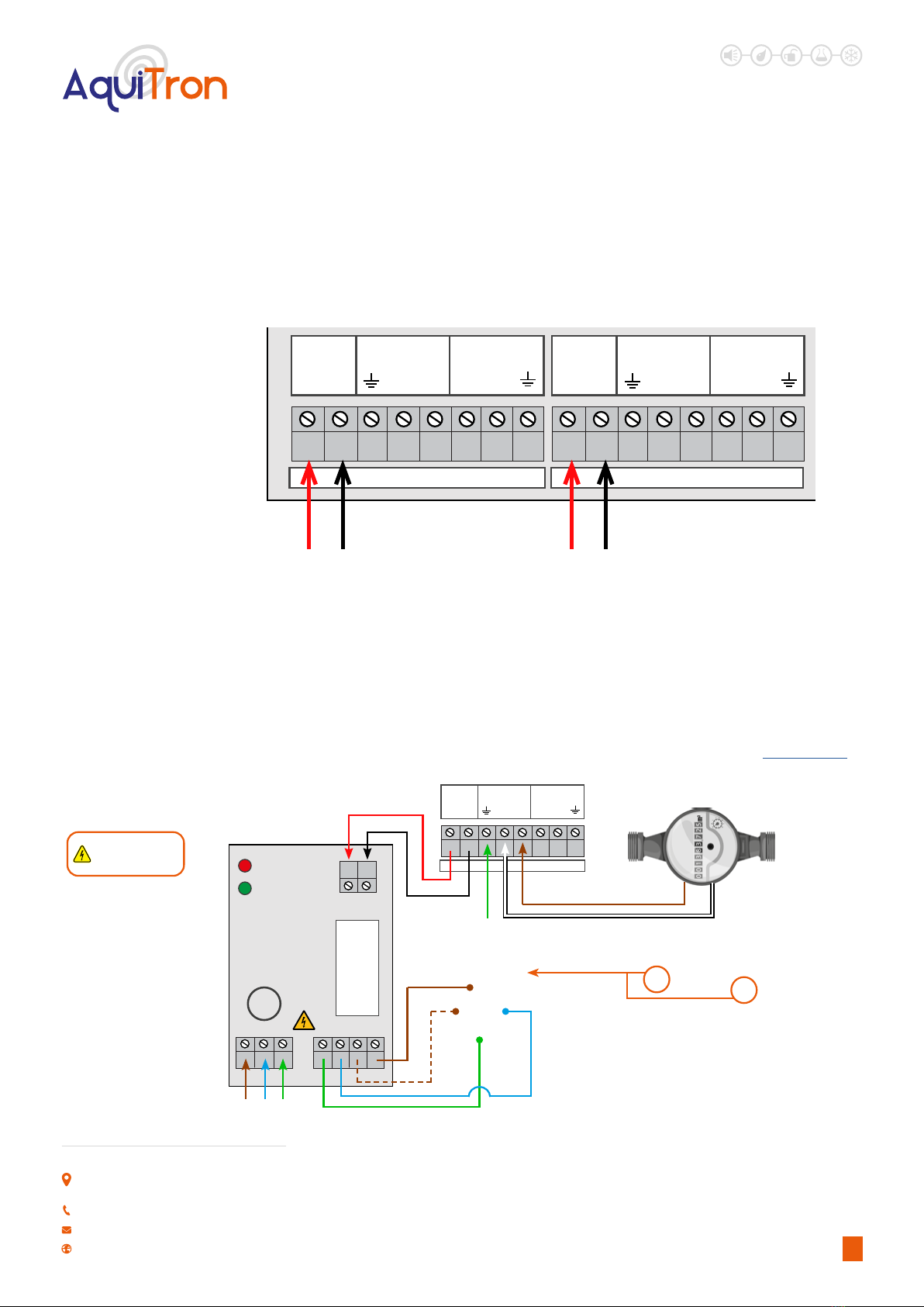
H5. SOLENOID VALVE CONNECTION
Figure 8 - Solenoid Vavle Connections
CHANNEL 1 CHANNEL 2
SOL 1 SOL 2METER 1 IN METER 2 INPULSE 1 OUT PULSE 2 OUT
+ - + -+ -+ -+ -
+ -
6Vdc Solenoid Valve
Connection Ch1 (External)
6Vdc Solenoid Valve
Connection Ch2 (Internal)
The AT-WFM can directly control two AT-V-P-xx or AT-V-B-xx solenoid valves only. The valves should be connected as shown above.
The valve should be connected to the same channel as the water meter. If two channels are being used with only one valve (standard
BREEAM setup) the valve should be connected to channel 2 (internal).
If using AT-V-xx or AT-BV-xx buttery or ball valves an AT-RU1 valve controller must be used. Please see the connection diagram below.
Power Connections to Relay (Mains), 230Vac supply L = Live, N = Neutral, E = Earth
Power Connections to Relay (Relay Valve), 230Vac supply L1= Live Close, L2= Live Open, N = Neutral, E = Earth
Control Connections from AT-WFM Controller 1= Solenoid +, 2= Solenoid -
NOTE: Wiring should only be done by a qualied electrician
Third party valves are not recommended for use with this controller. They can be controlled via the volt free relay output. See section H2.
AT-RU1 RELAY UNIT CONNECTIONS
Figure 8 - AT-RU1 Connections
3A
Close
Open
LE
N E N L1 L2
1 2
Water
Meter
CHANNEL 1
SOL 1 METER 1 IN PULSE 1 OUT
+ - + -+ -
Live
Neutral
Earth
Brown
White
IMPORTANT : All wiring
should only be done by a
qualied electrician
Pulse Ground
Connection
1 - Neutral
2 - Live (Opens Valve)
3 - Live (Close Valve)
E - Earth
1
2
3
E
L1 - Close Valve
L2 - Open Valve
AT-V-XX
Buttery Valve
AT-BV-XX
Ball Valve
AT-RU1
Relay Unit
Valve DIN plug
Connections

LEAK DETECTION SOLUTIONS
7
Unit 30, Lawson Hunt Industrial Park,
Broadbridge Heath, Horsham, West Sussex,
RH12 3JR
+44 (0) 1403 216100
www.aquilar.co.uk
H6. PULSE OUTPUT CONNECTION
Figure 9 - Pulse Output
Connections
The AT-WFM is equipped with an onbard two channel pulse splitter. This enable the unit to give real time ow volume information to
external equipment such as a BMS. A two core shielded cable should be used with the shield grounded at the AT-WFM in the relevant
ground terminal as shown above.
CHANNEL 1 CHANNEL 2
SOL 1 SOL 2METER 1 IN METER 2 INPULSE 1 OUT PULSE 2 OUT
+ - + -+ -+ -+ -
+ -
Pulse Output to BMS Ch1
(External)
Pulse Output to BMS Ch1
(Internal)
Pulse Shield /
Ground Connection
Pulse Shield /
Ground Connection
Note: Pulse outputs provided mirror the
pulses received from the water meters
connected to the Meter In connection(s).
I. HOME SCREEN
When rst turning on the AT-WFM it will boot up to the home screen. From his screen you have an overview of the system status and
settings. The information available is listed below.
D
D
E
F
ABC
G
H
I
J
A. Displays current screen
B. Displays date and time
C. Status LED:
• Green – System on and no
alarm present
• Red – System is in alarm
• Blue – System is in manual
override
• (Pulsing LED in any of the
above colours indicates
unit is running on battery
power)
D. Displays system status:
• Ok – System is monitoring
and no alarms present
• Leak – System has
detected a leak and is in
alarm
E. Displays valve status: Open
or closed
F. Displays volt free relay
status: On or O
G. Displays protection value:
Options for what is
displayed here will depend
on protection mode
selected.
H. Reset Alarm button
I. Displays protection mode
J. Menu button
Figure 10 - Home Screen
J. SETTING THE AT-WFM
The AT-WFM requires settings to be adjusted to suit the conditions of the application it is to be tted to. For correct operation it is essential
the information entered into the unit is as accurate as possible.
Once all connections have been made power should be applied to the AT-WFM. To ensure power is being received check the red mains
LED is lit on the main PCB.
The status LED on the front of the AT-WFM should be green to indicate it is monitoring and no alarms are present.

LEAK DETECTION SOLUTIONS
8
Unit 30, Lawson Hunt Industrial Park,
Broadbridge Heath, Horsham, West Sussex,
RH12 3JR
+44 (0) 1403 216100
www.aquilar.co.uk
K. MENU SCREEN
Home>>Menu
The menu screen has six buttons for navigating
around the AT-WFM.
Note: On all screens pressing the ‘Back’ button will
take you to the previous screen.
Figure 11 - Main Menu
K1. CONTROLLER INFO
Home>>Menu>>Controller Info
Figure 12 - AT-WFM Controller Information Screen
The Controller Info screen gives live detailed
information on the systems current setup and status
Status of System: Displays if the system is ‘Ok’, in
‘Leak’ alarm or has an ‘Error’.
Protection Level Times: This displays the current high
volume ‘Building occupied’ period see section L2B.
Current Operation Mode: Displays selected mode for
high volume period see section L3.
Valve Status (1&2): Displays whether valves are
enabled and if so whether currently open or closed
see section
Meter Value (1&2): Displays if meter is enabled, and if
so current live meter reading see section L4.
Software Version: Displays version number for
currently installed software
K2. INSTALLER INFO
Home>>Menu>>Installer Info
Figure 13 -Installer Information Screen
This screen displays the installer contact information.
By default it has Aquilar contact details loaded. These
details can be changed to show the details of the
installation / commissioning / current maintenance
company. See section L7.
LEAK DETECTION SOLUTIONS
9
Unit 30, Lawson Hunt Industrial Park,
Broadbridge Heath, Horsham, West Sussex,
RH12 3JR
+44 (0) 1403 216100
www.aquilar.co.uk
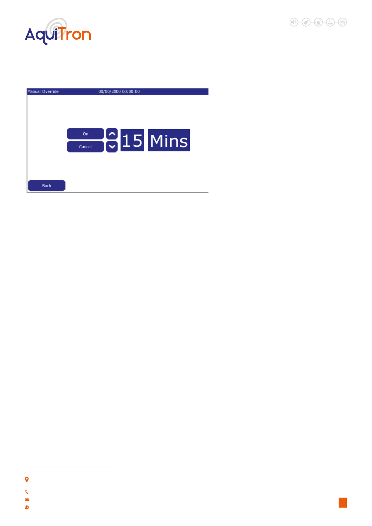
K3. MANUAL OVERRIDE
Home Screen>>Menu>>Manual Override
Figure 14 -Manual Override Screen
Note: Caution should be taken before enabling
the manual override as this means the system
will not go into alarm for the selected time period and
your building will not be protected.
Pressing the on button enables the override. There are
four pre-set override time periods available. 15, 30, 45
and 60 minutes. These are selected by using the up or
down arrow.
Once a time period is selected the status LED will
change to blue and a countdown begins and runs for
the selected time period. Once this has reached zero
the status LED will return to green and the system will
automatically go back to normal operation.
Manual Override can be cancelled at any time by pressing the cancel button. The system will then revert back to normal operation as per
the programmed parameters.
K4. EVENT HISTORY
Home Screen>>Menu>>Event History
Figure 15 - Event History Screen
The events history contains information on any alarms
and programming/setup changes. The system will
retain the last 1000 events. Once this is full the oldest
events will drop o the list as new ones are recorded.
All events recorded have a date and time stamp and
are ordered according to this. With the most recent
events listed rst at the top of the list.
Use the arrows beside the events screen to scroll
through to older events.
Important Note: For accurate recording of events, the
date and time must be set up accurately on the system
during commissioning (see section L1.)

LEAK DETECTION SOLUTIONS
10
Unit 30, Lawson Hunt Industrial Park,
Broadbridge Heath, Horsham, West Sussex,
RH12 3JR
+44 (0) 1403 216100
www.aquilar.co.uk
L. SETUP (FOR AUTHORISED USERS ONLY)
Home Screen>>Menu>>Setup>>Password>>Enter
To prevent unauthorised tampering with settings,
pressing the setup button in the menu screen will ask
you to input a password before entering into the setup
menu.
Using the on screen keyboard input AT-WFM then
press enter. DEFAULT PASSWORD : ATWFM Use
Capitals
This will open the setup menu.
Figure 16 - Setup - Password Screen
From this page you can access the screens necessary
to setup the AT-WFM controller.
Figure 17 - Main Setup

LEAK DETECTION SOLUTIONS
11
Unit 30, Lawson Hunt Industrial Park,
Broadbridge Heath, Horsham, West Sussex,
RH12 3JR
+44 (0) 1403 216100
www.aquilar.co.uk
L1. DATE AND TIME
Menu>>Setup>>Password>>Date and Time
Figure 18 - Date / Time Setup Screen
Important Note: For correct operation of the
system it is essential the date and time are
correctly entered here.
To adjust the date and time press the edit button
under the value you wish to adjust.
Use the side arrows to select the value you wish to adjust, then the up and down arrows to select the required value. Only true values can
be selected. Press enter to return to the time and date screen then enter to save the values and return to the setup menu.
Note: The AT-WFM system has a real time clock that will retain the correct time and date in the event of power loss.

LEAK DETECTION SOLUTIONS
12
Unit 30, Lawson Hunt Industrial Park,
Broadbridge Heath, Horsham, West Sussex,
RH12 3JR
+44 (0) 1403 216100
www.aquilar.co.uk
L2. PROTECTION LEVEL MODE
Menu>>Setup>>Password>>Protection Level Mode
Protection Level mode is the measurement used to monitor the ow through the pulse meters. There are three modes available:
• Volume per
• Timed
• Crosscheck
The other settings available on this screen will change according to the mode selected.
L2.A VOLUME PER
Figure 19 - Protection Level - VOLUME MODE
Default setting is ‘Volume Per’. In this mode the
system will allow a set amount (volume) of water
through the pulse meter during a dened period. e.g.
1500ltr water volume allowed in any half hour period.
In this setting there are three further options for
dening that period:
• ½ Hour
• Hour
• Day
By combining these values you increase or decrease
the ‘sensitivity’ of the systems measurement of ow
volume.
To edit the ow volume, press the edit button under the high or low volume value you wish to adjust to enter the value edit screen. Then
use the arrows to select and adjust values, then press enter to save and return to the screen above. (See section L3. on adjusting high low
volume times).
In the example shown in Fig.19 above the system will allow 1500ltr per half hour during high volume periods, and 60ltr per half hour
during low volume periods. Any water use above this level will put the system into alarm.
L2.B TIMED
Timed does not measure volume. Instead it will
allow water ow for dened periods of time. Periods
available are:
• 10 minutes
• 15 minutes
• 30 minutes
• 60 minutes
Any uninterrupted ow above this user dened time
will put the AT-WFM into alarm. In the example in g.20
the unit is set for 10 minutes. If the water ows for 11
minutes the system will go into alarm. If the water runs
for 9 minutes, stops, then ows for another 9 minutes,
stops, etc the system will not go into alarm.
Figure 20 - Protection Level - TIMED MODE
There are two reset options available:
Manual Reset – The Reset button must be pressed to stop the alarm and reset the controller
Automatic Reset – The controller will automatically reset as soon as the water ow stops
Note: A ow switch can be used in place of pulse water meters on this setting if required.

LEAK DETECTION SOLUTIONS
13
Unit 30, Lawson Hunt Industrial Park,
Broadbridge Heath, Horsham, West Sussex,
RH12 3JR
+44 (0) 1403 216100
www.aquilar.co.uk
L2.C CROSSCHECK
Figure 21 - Protection Level - CROSSCHECK MODE
Crosscheck gives the AT-WFM exibility to be used
in applications where a comparison of two meters is
required, e.g. a block of ats with heat interface units,
especially useful if ats are left unoccupied for long
periods. The ow and return into each at can be
monitored. If more water goes in than comes out then
the water loss will be noted by the AT-WFM and an
alarm generated.
There are two adjustment in this section that aect the
sensitivity of alarm conditions, tolerance and volume
per.
Tolerance is measured in percentage and allows a dierential of up to 20% between channel pulse inputs. Options are:
• 0%
• 10%
• 20%
Volume per species the period of measurement. Options are:
• ½ hour
• Hour
• Day
e.g.1. Select tolerance 10% and volume per ½ hour. This means each half hour if the pulse input of each channel varies by more than
10% the system will go into alarm. On this setting an expected 100ltr measurement could vary by up to 20ltrs per half hour before an
alarm would be given. Total of 480ltrs per 24 hour period.
e.g.2. Select tolerance 20% and volume per Day. This allows up to 20% dierence in channel pulse inputs in any 24 hour period. On this
setting an expected 100ltr measurement would only allow 40ltrs dierence over a 24hr period.
Important Note: Selecting 0% tolerance requires the pulse inputs to be matched at all times.
Important Note: For eective operation identical pulse Meters with high accuracy must be used. Contact Aquilar for details on our
range of suitable water meters.

LEAK DETECTION SOLUTIONS
14
Unit 30, Lawson Hunt Industrial Park,
Broadbridge Heath, Horsham, West Sussex,
RH12 3JR
+44 (0) 1403 216100
www.aquilar.co.uk
L3. PROTECTION LEVEL TIME
Menu>>Setup>>Password>>Protection Level Time
Figure 22 - Protection Level Time
Time select options are:
• Daily – Times are the same for all days
• Weekly – Dierent times can be set for each
day (each day must be set individually)
• Week/End – Times are set for week days and
weekends separately
• Ext Input – High and low volume times are
triggered via an external input such as a key
switch or alarm system i.e intruder alarm for
entry / exit setting. Trigger inputs must be a
normally open volt free contact (See section
H.2, closing to trigger into low volume. (See
section H.3 for connection information)
In this screen you set the start and end times required for high volume level. Any time outside of the parameters input here are
considered low volume level by the controller, and will be measured as such according to the volume levels in put in section H2. Volume
per.
The general rule for the high volume times is to set this higher value for when the building is occupied. Eg. For an oce you may want
to set the high volume (building is occupied) period to start at 8.00 and end at 18.00. In this example in the time between 6pm and
8am the controller will be using the low volume (building is unoccupied) setting.
In all options press the edit button under the value you wish to adjust to enter the edit screen, then use the arrows to select and enter
the value, press enter to save.
L4. METERS
Menu>>Setup>>Password>>Meters
Figure 23 - Meters Pulse Screen
The meter (pulse inputs) are enabled on this screen.
The example in g.23 shows meter 1 enabled (on)
and meter 2 o. If two pulse meters are being used
both should be enabled here.
To enable, or disable, a meter simply press the on/o
button on the screen.
The meter values shown on the meter dials should
be entered using the edit buttons. This will ensure
the meter readings match the controller readings to
make meter reading possible from one position, at
the AT-WFM.
LEAK DETECTION SOLUTIONS
15
Unit 30, Lawson Hunt Industrial Park,
Broadbridge Heath, Horsham, West Sussex,
RH12 3JR
+44 (0) 1403 216100
www.aquilar.co.uk
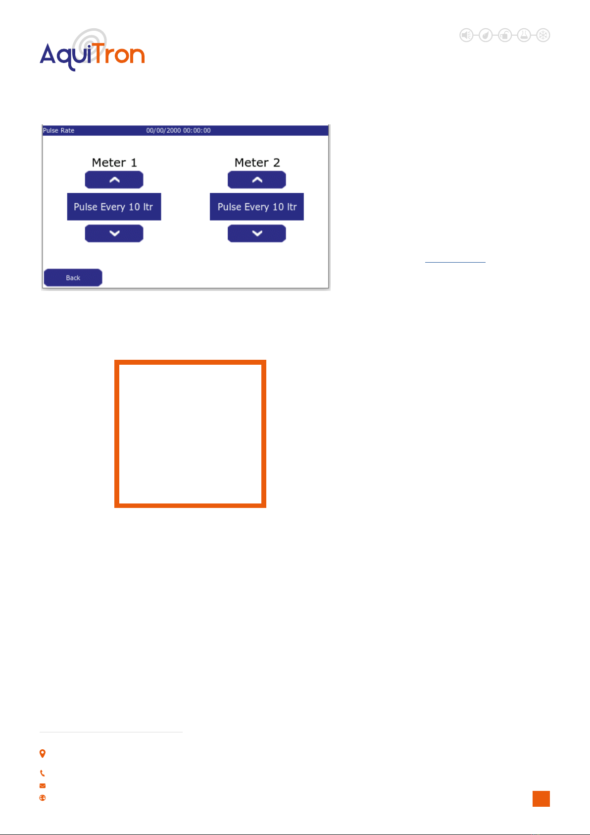
L5. PULSE RATE
Menu>>Setup>>Password>>Pulse Rate
Figure 23 - Meters Pulse Rate Setup
Pulse rates for the water meters connected to the
system are selected here. Options available are
pulse every: 1, 10, 100 litres. It is important that the
pulse selected should match the output from the
meter tted. If not the system will not be able to
accurately measure water volume.
Please contact Aquilar if you require a suitable pulse
meter.
Note: If this screen is blank it is because no meters
have been enabled. (See section H4)
Fig 23.a shows a typical pulse
transmitter, this is where a pulse is
taken to be connected to the AT-WFM
control panel.
Figure 23.a - Typical Cyble

LEAK DETECTION SOLUTIONS
16
Unit 30, Lawson Hunt Industrial Park,
Broadbridge Heath, Horsham, West Sussex,
RH12 3JR
+44 (0) 1403 216100
www.aquilar.co.uk
L7. CHANGE INSTALLER INFO
Menu>>Setup>>Password>>Change Installer Info
Figure 25 - Installer Information Change Screen
On this screen the installer information can be
changed. By default Aquilar details are shown.
To make changes to the information shown simply
press the ‘Change’ button next to the information
you wish to adjust. This will bring up the on-screen
keyboard. Type in the new information and press
enter to save.
Note: Entering no information, not pressing enter, or
pressing back will keep the existing information.
L6. VALVES
Menu>>Setup>>Password>>Valves
Figure 24 - Valve(s) Setup Screen
If valves are tted they must be enabled here for the
system to control them. To enable or disable use the
on screen On/O button for each valve. See section
H5. For connection details.
IMPORTANT NOTE: Only use AquiTron valves on this
system.
See Section B “Types Of Valves”.

LEAK DETECTION SOLUTIONS
17
Unit 30, Lawson Hunt Industrial Park,
Broadbridge Heath, Horsham, West Sussex,
RH12 3JR
+44 (0) 1403 216100
www.aquilar.co.uk
PO POWER ON
Device powered on
POWER OFF
Mains power lost, operating from battery
System detected that mains power to the unit has been removed and that the system is operating from the battery. This message will not
be logged if power is removed and there is no battery backup.
MAINS POWER RETURNED
Mains power returned
System has detected that the mains power to the unit has been restored and the display has returned to normal operation. This message
will not be logged if power is removed and there is no battery backup.
LA LEAK ALARM
Leak Alarm
Message to record the time when a new leak is discovered. This message will be logged every time the system goes into alarm
AR ALARM RESET
Alarm Reset
Message to record that the system has been reset.
Log messages can only be viewed directly on the screen under Menu > Event History. It is possible to scroll through them by using the
up and down arrows.
M. EVENT LOG MESSAGES
L8. FACTORY REST
Menu>>Setup>>Password>>Factory Reset>>Conrm
Figure 26 - Factory Reset Screen
The AT-WFM can be reset back to factory default
settings. If this screen is selected you will be asked
to conrm or cancel this action. To exit without
resetting press cancel. To proceed press conrm.
All settings will need to be re-entered, including time
and date.
Important Note: This action will revert the unit back
to default settings and delete all history. It is non-
reversible.

LEAK DETECTION SOLUTIONS
18
Unit 30, Lawson Hunt Industrial Park,
Broadbridge Heath, Horsham, West Sussex,
RH12 3JR
+44 (0) 1403 216100
www.aquilar.co.uk
Important: All information, including illustrations, is believed to be reliable. Users, however, should independently evaluate the suitability
of each product for their application. Aquilar Limited makes no warranty as to the accuracy or completeness of the information, and
disclaims any liability regarding its use. The only obligations of Aquilar Limited are those in the Aquilar Standard Terms and Conditions of
Sale for this product, and in no case will Aquilar Limited be liable for any incidental, indirect, or consequential damages arising from the
sale, resale, use or misuse of the product. Specications are subject to change without notice. In addition, Aquilar Limited reserves the
right to make changes – without notication to Buyer
– to processing or materials that do not aect compliance with any applicable specication.
AquiTron is a trademark of AquiTron Limited
Aquilar is a trademark of Aquilar Limited
V1.2 06.2022
SYSTEM FAULT
System Fault
Message will be displayed when a system fault has been detected, if problem persists please contact Aquilar.
MC PROTECTION LEVEL MODE CHANGED
Protection level mode changed to XXXX (X can be volume per, timed, crosscheck)
Logs a mode change upon exit of the Protection Level Mode screen.
TC PROTECTION LEVEL CHANGED
Protection level time changed to XXXX (X can be daily, weekly, week/weekend, Ext input)
Logs a time change upon exit of the Operating Mode screen.
VC PROTECTION VOLUME CHANGED
Protection volume XXXX changed to YYYY (X can be high or low, Y is the new volume amount)
Logs that manual override mode has started upon exit of the manual override screen.
OS MANUAL OVERRIDE STARTED
Manual override started for XXXX (X will be the time the manual override has been set for)
Logs a change to either high volume amount or low volume amount upon exit of Protection Level Mode screen whilst volume per mode is
selected.
OS MANUAL OVERRIDE ENDED
Manual override ended: XXXX (X can either be timeout or manual)
Logs that manual override mode has nished by either timeout or it has been cancelled manually.
Table of contents
Other aquilar Measuring Instrument manuals


