Sontay SD-D User manual

© 2017 Sontay Limited. All rights reserved
SD-D
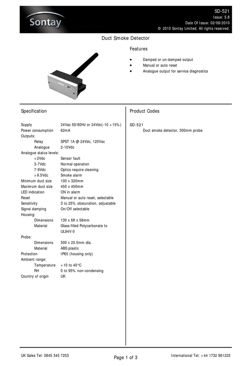
Duct Smoke Detector
Issue Number 7.1
30/09/2021
Four Elms Road - Edenbridge
Kent - TN8 6AB - UK
1 of 3
Features and Benefits
Product Codes Specification
SD-SDuct smoke detector
Technical Overview
The SD-D duct smoke detector operates on the obscuration principle, using infrared technology and is designed specifically to cope with the
difficult measurement conditions in air ducts, such as high velocity and levels of dirt accumulation. The relay output is either auto or manual
reset relay output on detection of smoke.
Supply 24Vac/dc, ±20%
Power consumption 50mA max.
Relay outputs (smoke & fault)
SPST 2A @ 48V
Minimum duct size 100 x 320mm
Maximum duct size 450 x 450mm*
LED indication ON in alarm
Alarm relay (selectable) Manual or auto reset
Probe:
Dimensions 300 x 20mm dia.
Material Plastic
Housing:
Material PC/GF (Halogen free, flame retard
ant & UV stabilized)
Dimensions 125 x 105 x 85mm
Environmental:
Housing: -30 to +60°C
20 to 80% non-condensing
Media: 10 to 40°C
Protection IP65
Country of origin Denmark
Conformity EMC, CE & UKCA Marked
* Please see recommendations on page 2.
• Manual or auto reset
• Fault relay output
• Self-test feature
WEEE Directive:
At the end of the products useful life please
dispose as per the local regulations.
Do not dispose of with normal household waste.
Do not burn.

© 2017 Sontay Limited. All rights reserved
SD-D
Duct Smoke Detector
Issue Number 7.1
30/09/2021
Four Elms Road - Edenbridge
Kent - TN8 6AB - UK
2 of 3
How It Works
The sensor works by using an infra-red transmitter and receiver fitted to the PCB inside of the housing. The transmitting device sends a beam,
which is reflected from a mirror in the end of the 300mm long probe, and the receiving device then receives this beam when there are no ob-
stacles, like smoke partials in the tube. If smoke is present, then this will disturb the beam, and the receiver will lose the signal and an alarm
will be activated.
Calibration at start-up
On power up the SD-D will start an automatic calibration procedure, the power from the TX device will increase in small steps, just until the RX
device receives enough signal to validate the “link”. This is stored in the volatile memory for any further use, or until a new power on. Now any
obstacles, like smoke will force an alarm.
Periodic calibration
The mirror over time may lose the possibility to reflect the full IR light level due to a contamination build up, such as dust. Periodic calibration is
carried out automatically by the smoke detector every 7 days to compensate for this.
Recommendations
• The SD-D has a probe length of 300mm and should NOT be used in ducts with a diameter or square size greater than 450mm, unless
the smoke detection is intended as a secondary non-life safety action with areas served being covered by smoke detection connected
to a fire alarm system that is able to shut-off the ventilation fans, as it will not monitor the whole of the duct.
• Must be mounted AFTER filters and humidification plant, this will prevent any spurious alarms caused by dust or water vapour.
• Units should NOT be mounted where ambient sunlight will fall on the photocell.
• Units should never be mounted at or near sharp bends in ductwork, as turbulence and side currents can carry the smoke away from
the probe.
• The SD-D is an optical beam detector and therefore, air velocity has little effect on performance. However, careful positioning of the
detector is required if optimum detection is to be achieved. The detector should always be fitted with the holes in the sensing tube par-
allel to the airflow.
• Units should not be mounted close to supply or extract fans.
• With large installations, where several ducts collect into a common duct, consideration must be given to dilution of smoke and rate of
airflow. For example, 10 small ducts may feed at different points into one large main extract duct, and if only one smoke detector is
fitted in the main extract duct, the position can arise where one duct is feeding smoke and nine are feeding clean air. The amount of
smoke is therefore diluted by 90%, and if this is coupled with a high flow rate, the smoke may not be detected for the minimum operat-
ing period of 1 second, resulting in no alarm being generated. It may be necessary to mount 10 detectors in each of the small ducts to
guarantee correct operation.

© 2017 Sontay Limited. All rights reserved
SD-D
Duct Smoke Detector
Issue Number 7.1
30/09/2021
Four Elms Road - Edenbridge
Kent - TN8 6AB - UK
3 of 3
Installation
1. The SD-D should only be installed by a competent, suitably trained technician, experienced in installation with hazardous voltages.
(>50Vac & <1000Vac or >75Vdc & 1500Vdc)
2. Ensure that all power is disconnected before carrying out any work on the SD-D.
3. If the sensor is mounted outside, it is recommended that the unit be mounted with the cable entry at the bottom. If the cable is fed from
above then into the cable gland at the bottom, it is recommended that a rain loop be placed in the cable before entry into the sensor.
4. Select a location in the duct where dust & contaminants are at a minimum (i.e. after filters etc.). Fix the housing to the duct with appro
priate screws.
5. Release the snap-fit lid by gently squeezing the locking tab.
6. Feed the cable through the waterproof gland and terminate the cores at the terminal block. Leaving some slack inside the unit, tighten t
he cable gland onto the cable to ensure water tightness. Maximum cable is 2.5mm², care must be taken not to over tighten terminals.
7. Ensure the supply voltage is within the specified tolerances and snap shut the lid after the connections have been made.
Connections
1. Fault Output Common
2. Fault Output Normally Closed*
3. Smoke Detection Output Common
4. Smoke Detection Output Normally Closed*
5. Supply +24Vac/dc, ±20%
6. Supply 0V
* See alarm conditions
Changing Reset Modes
Manual to Auto reset
•Press and hold the external reset button
•After approx. 5 seconds, the internal green LED will go off for 1 second.
•Release the button and the device is now in auto reset mode. The PCB mounted LED will be constantly lit green.
Auto to Manual reset
•Press and hold the external reset button
•After approx. 5 seconds, the internal green LED will go orange and the external LED will go red for 1 second.
•Release the button and the device is now in manual reset mode. The PCB mounted LED will be constantly lit green.
Calibration & Alarm Conditions
While the detector is auto-calibrating, the internal LED will flash red 6 times a second. When calibration is finished, the LED will change to or-
ange for a few seconds, the calibration is being stored in the volatile memory.
The PCB LED will then be continuously lit green, this also indicates that the sensor is powered correctly and not in alarm.
If the detector is in alarm or a fault has occurred, the internal & external LED’s will change to red.
Under normal operating conditions the relay is energised. Therefore, if any fault develops the relay will de-energise shutting off the equipment
connected to the relay, i.e burner or circulating fan, rendering the installation safe.
Relay status
• Un-powered Open
• Powered Closed
• Alarm Open
Self-Test, Failure Mode & Manual Reset
• The output of the SD-622 can be manually overridden, to check integrity of the field wiring. To operate press the PCB mounted button.
In self-test mode both relay outputs will open, the external and the internal LED will be red.
• The external LED will flash red if the detector fails.
Test
button
LED
SUPPLY
IN
24Vac/dc
RELAY
OUT
FAULT
1 2 3 4 5 6
COM NC COM NC +IN GND
RELAY
OUT
SMOKE DET.
TEST
Whilst every effort has been made to ensure the accuracy of this specification, Sontay cannot accept responsibility for damage, injury, loss or expense resulting
from errors or omissions. In the interest of technical improvement, this specification may be altered without notice.
Table of contents
Other Sontay Smoke Alarm manuals
