Filtec FT-50 Assembly instructions

Downstream Inspection
Station
Installation and Setup Guide for
Models FT-50 and FT-70
2516-1092

Downstream Inspection Station
Installation and Setup Guide for Models FT-50 and FT-70
Document 2516-1092

Industrial Dynamics Company, Ltd.
Document 2516-1092 Copyright. All rights reserved.
No part of this publication may be reproduced or used in any form or by any means (graphic,
electronic, or mechanical including photocopying, recording, taping, or information storage
and retrieval system) without written permission of Industrial Dynamics Company, Ltd.
Filtecand Industrial Dynamicsare registered trademarks of Industrial Dynamics Company,
Ltd. All other trademarks are the property of their respective owners.
Contact Information
Corporate Headquarters: 3100 Fujita Street,
Torrance, California
90505-4007
U.S.A.
Telephone:(310) 325-5633
FAX: (310) 530-1000
Internet: www.filtec.com
Mailing Address: P.O. Box 2945,
Torrance, California
90509-2945
U.S.A.
Shipping Address: 3100 Fujita Street,
Torrance, California
90505-4007
U.S.A.
Customer Service: (800) 733-5173

FT-50/70 DOWNSTREAM INSPECTION STATION
The DownstreamInspection Station is
a
floor mounted structure
with adjustable arms and brackets that allow inspection devices
to
be
located
in
various positions not possible in the inspection
tunnel area. These
stations
offer positioning versatility
to
place
the sensors where needed relative
to
the conveyor, the
FT
-
50/70
InspectionHead and the container. Typical applications for the
stations include:
Crossbeam
Body
Label Detector
Variable Angle
Full
Wrap Label Detector
Raster Scanner
Multiple
Body
Label
Detectors
on
the Same Station
Front and Back Labels or Single Label Quad Beam
Detector
When multiple Downstream Inspection Station Mounting Stands
are used with the same
FT
-
50/70
Inspection System, the stand
closest
to
the
FT-50/70
Inspection
Head will be
designated
Station
No.
1;
the next stand
will
be Station
No.
2;
etc.
A
DownstreamInspection Station consists
of
the
following
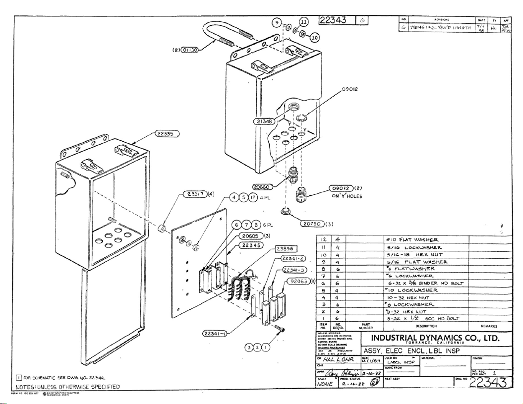
standard assemblies (refer
to
Drawing
22344):
Tripod
Floor
Mount
Vertical Support Pipe Assembly
Tripod Support Braces
SquareTube Mounting
Base
Block
One Horizontal SquareTube,
24
inch
(610
mm)
long
Two Vertical SquareTubes,
18
inch
(457mm)
long
Two Adjustable Tube Brackets
Junction
Box
and Mounting Hardware
The
tripod
floor
mount,
a
16
inch diameter tripod, and the
vertical support
pipe,
which includes the mounting base plate,
provide
a
mounting
surface
a
maximum
of58.5
inches (1,486
mm) above the floor surface.
The
pipe
is
cut
-
to
-
fit during
installation. Longer
pipes
may be supplied for higher conveyor
requirements. The
tripod
support braces provide additional
vertical stabilityand rigidity to the unit.
All frame tubes
are
one inch
(25mm)
square stainless steel that
provide
a
solid, non
-
rotating base for the sensors.
The
adjustable
bracket positions the sensor mounting perpendicular to the cross
tube in either a vertical or horizontal attitude. Scales, providing
both English and metric measurement, are placed on the
mounting tubes where precise alignment
of
sensors
is
required.
Locking ratchet knobs on the brackets provide easy adjustment
of
tube positions while ensuring positive position retention
when tightened.
Industrial
Dynamics
Company,
Ltd.
2516-1092
1

The tubes and brackets included may vary from system to
system based on special applications assigned
to
the stations.
The Electronics Enclosure (JunctionBox) houses the amplifiers
and other electronics for the inspection devicesassigned
to
the
station and interfaces the devices to
the
FT
-
50/70
Inspection Head
through asingle multi
-
conductorcable. Figure
1
illustrates a
station where sensorsare placed on both sides of the conveyor.
Figure
1.
Station
with
Sensors
on
Both Sides
of
Conveyor
2
Industrial
Dynamics
Company,
Ltd.
2516-1092

Installation Requirements
and
Instructions
Installation of the DownstreamInspection Station Mounting
Stand, with appropriateinspection devices,
will
generallybe
performed
at
the same
time
as
the
FT
-
50/70
System it is being used
with. Refer to the installation instructions
in
the
FT-50/70
Service
Manual before installing the station.
The Downstream Inspection Station with the applicablesensors
mountedin their approximate
operating
location is shipped with
minimal assembly required. The
sensor
mounting frame
is
unbolted from the remainder
of
the stand, but wiring
is
complete. The sensor mounting frame
is
separatedfrom the
remainder of the stand
at
the
point
the Vertical Support Pipe
(22331) connects
to
the Mounting Block
(22328)
with four 1/4
-
20
x
1/2 inch bolts (refer to Drawing
22344).
This allows the
mounting frame
to
be lowered from the perpendicular position
and placed in the shipping container.
Assemble the Vertical Support Pipe (22331) to the Mounting
Block (22328)before proceeding with the mountinginstructions
in the following paragraphs.
CAUTION:
The Downstream Inspection Station is not balanced
on
the
tripod stand. Therefore, when you remove the stationfrom
its
box
(and assemble, if required) and place it in an upright
position, make sure
you
supportthe end farthest from the
supportpipe
at
all times until the tripod is firmly attached to
the floor.
Position of the station relative to the conveyor is shown
on
Installation Drawing I-00399.Refer
to
this drawing, located
at
the end
of
this appendix, when performing the procedures in
the following paragraphs.
Refer to the installation instructions
or
drawing for your system
to
determine the location
of
the
station relative
to
the
FT
-
50/70
Inspection Head and Rejector.
Also
refer
to
the drawing for any
changes
to
the height
of
the structure relative
to
the
top
surface
of the conveyorchain. The standard height and positioning
specificationsare given
on
the Installation Drawing,
as
follows:
Underside of the
cross
tube to the
top
of the conveyor chain
should be approximately 16 inches (406
mm).
Centerlineof the Vertical Support Pipe
to
the Centerline of
the conveyor chain should be
13-1/2
inches
(343
mm).
Using these dimensions, install the station as described on the
Installation Drawing and
in
the following paragraphs.
Industrial
Dynamics
Company,
Ltd.
2576-1092
3

lnstallation
lnstructions
1.
Remove guide rails on both sides
of
conveyor and level
2.
Assemble Tripod
Floor
Mount
(11287)
using four
3/8
-
16
x
1
"
hex head bolts with
flat
and lock washers. Leave bolts loose
for
later adjustment.
conveyor both across and parallel to chain.
3.
Refer
to
Figure
2
to
cut vertical
support
pipe. Cutting the
pipe
is
an important
step,
so
do
it carefully.
a. In location where station
is
to
be installed, measure
distancefrom
top
of
conveyor chain
to
floor
(Hc).
Use following equation to find length
of
pipe:
b.
Lp
=
Hc
+
12-3/8”
c. Cut the pipe to length
Lp.
4
Figure
2.
Height
of
Vertical SupportPipe
Industrial
Dynamics Company,
Ltd.
2516-1092

4.
Place the properly cut pipe assembly in Tripod Floor Mount.
Install three Tripod SupportBraces
(22022)
using
5/16
x
1
"
bolts and hardware, tighten finger tight.
(Be
sure braces are
mounted on proper side
of
Tripod Floor Mount as shown
in
Drawing
22344.)
Mount Pipe Clamp
(22135)
as shown
to
hold
three braces, tighten clamp just enough
to
hold braces
in
place.
NOTE:
Prior to installing the three supportbraces, it may be necessary
to
loosen or remove
the
bottom U
-
bolt securing
the
Junction
Box
to the supportpipe
to
allow placement
of
the braces
against the pipe. Reinstall the U
-
bolt when completed.
5.
Position the assembled station
so
the centerline
of
the vertical
support pipe
is
13.5
inches from the centerline of
the
conveyor chain and
the
correct distance downstreamfrom the
centerline
of
the
FT
-
50/70
Inspection Trigger. The station is
positioned downstream of the Inspection Head but before the
Rejector. The Rejector can be up to
32
container diameters
downstream
of
the Inspection Trigger. The inspection
centerline of the station must be
a
minimum
of
one container
diameter plus one millimeter
from
both the Trigger centerline
and
the
Rejector centerline. Refer
to
the Appendix describing
your Label Inspection application for the correct distance.
Refer to InstallationDrawing
I-00399
for
orientation
of
stand
flanges relative to the conveyor flow.
CAUTION:
The assembled station is notbalanced
to
stand by itself
without securing
to
the floor and will tip over if not held or
supported.
Align entire structure
so
the support pipe is vertical and the
cross tube
is
perpendicular
to
conveyor
flow
and parallel to
the conveyor chain surface.
6.
Mark position
of
tripod
floor mount holes on floor. Move unit
and drill holes in floor for mounting inserts. Place inserts in
holes and set tripod in place. Insert and tighten lag bolts just
tight enough to hold station in place.
7.
Check
cross
tube alignment with respect to conveyor chain.
Cross
tube must be level, check by placing level on
top
of
mounting plate
(22330).
Make final adjustmentsby moving
support pipe in clamped tripod braces.
Industrial Dynamics Company,
Ltd.
2516-1092
5
When the Inspection Head
is
properly aligned, tighten the
following:
pipe
clamp and three bolts that hold the
tripod
braces, three
lag
bolts that secure the tripod floor stand, four
bolts in the
tripod
clamping flange.
8.
When the station
is
mounted in the proper position over the
conveyor, tack
weld
the tops of the three
tripod
support
braces. After welding, remove the pipe clamp and discard.
9.
Connect the cable from the station Junction Box
to
the
FT
-
50/70
Inspection Head. Route the multi
-
conductorcable through
a
watertight cable connector in the bottom of the Inspection
Head and connect the wires to the
IT
-
50
Main Terminal Block
TB1
as
shown
on
Drawing
22344.
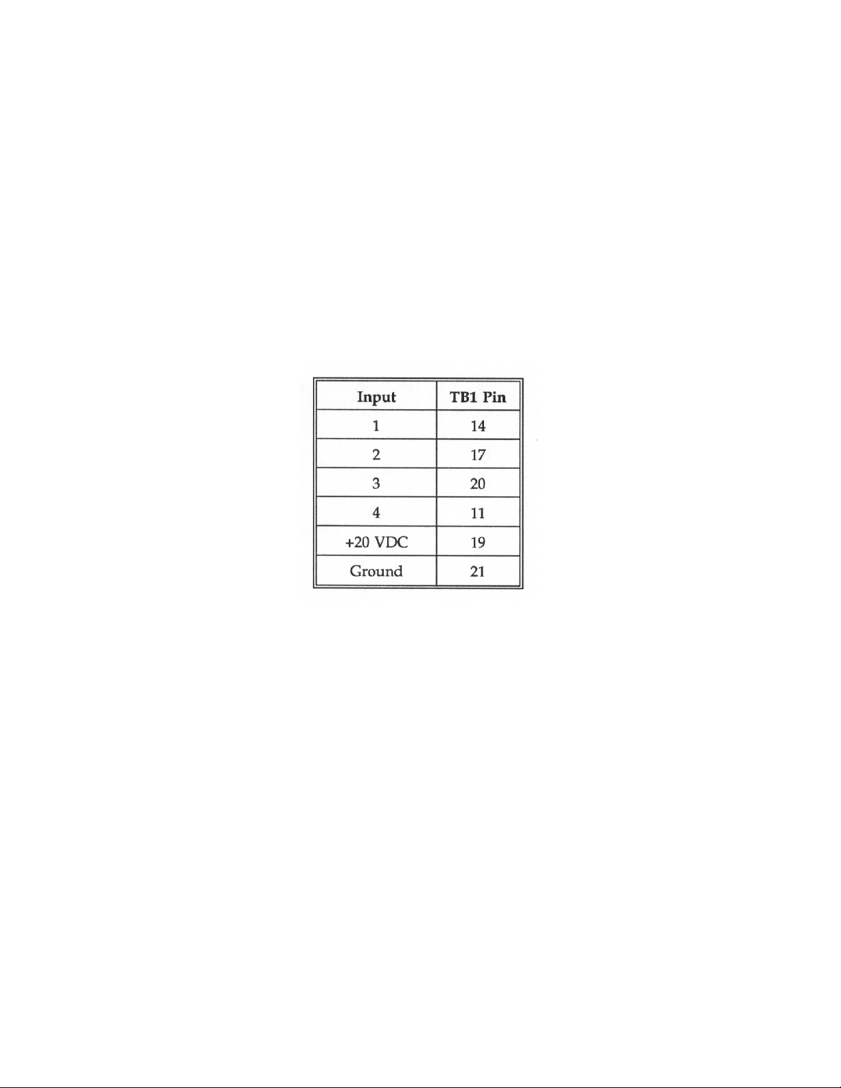
The standard connections
are
as
follows:
The inspection functions assigned
to
Inputs
1
through
4
in
your system
can
be
determined by using
the
VIEW
TB1
PIN
ASSIGNMENTS
Subfunction to display the names assigned to
each input. If the
TB1
pin connections are
to
be other than the
standard,
a
separate
wiring diagram will
be included with the
documentationsent with your system.
The remainder
of
the installation instructions
for
the station
will be included in the appendix describing the inspection
functions assigned to this station.
Alignment Procedures
Once
the
station
has
been setup
so
the horizontal tube
(22334)
is
perpendicular
to
conveyor flow and parallel
to
the conveyor
chain surface and bolted
to
the floor, the design
of
the station
should keep the structure in alignment. If realignment
is
necessary, review
the
installation procedureand perform the
alignmentas necessary.
6
Industrial
Dynamics
Company,
Ltd.
2516-1092


Other manuals for FT-50
3
This manual suits for next models
1
Table of contents
Other Filtec Industrial Equipment manuals


