Tennsmith LM1014 Guide

Model LM1014 Performance “F”
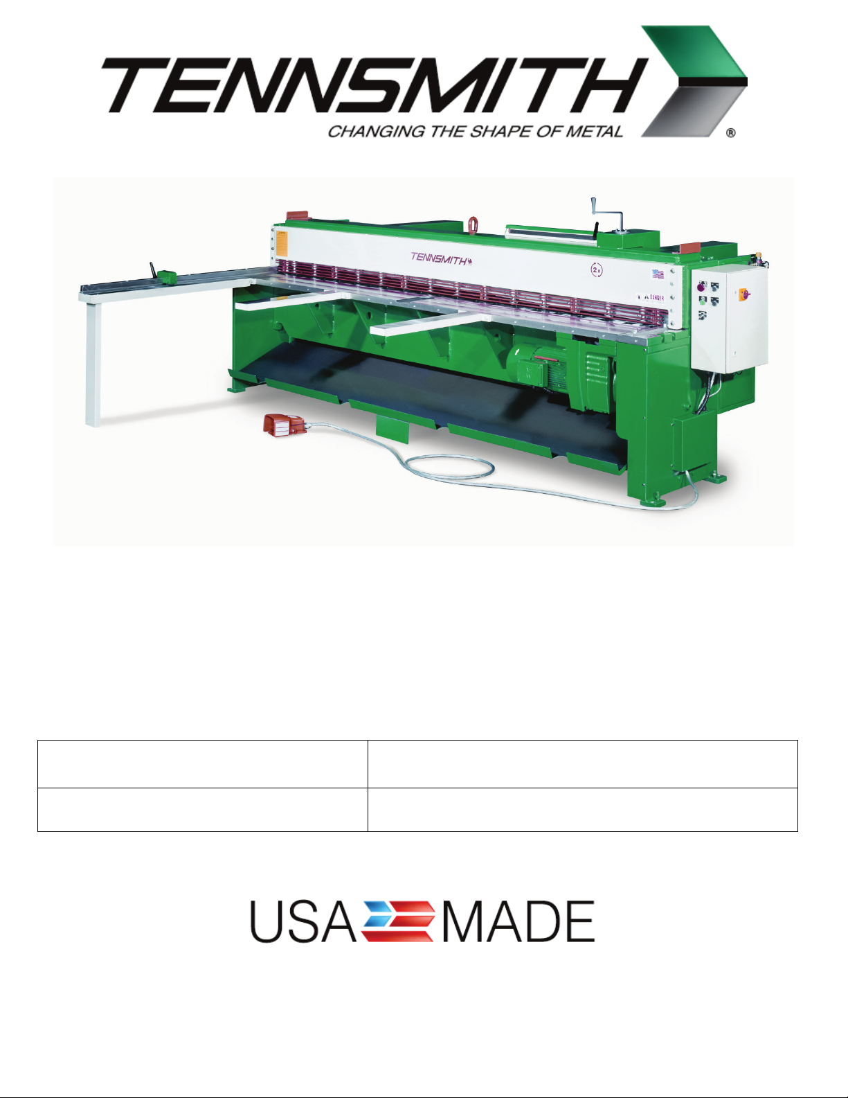
MODEL LM1014 MECHANICAL SHEAR
OPERATION, PARTS & MAINTENANCE MANUAL
Model: Purchased From:
Serial #: Date Received:
6926 Smithville Hwy., McMinnville, TN 37110
931-934-2211 / Fax: 931-934-2220
www.tennsmith.com

2
TABLE OF CONTENTS
SUBJECT PAGE NUMBERS
SHEAR SPECIFICATIONS 3
WARRANTY INFORMATION 3
SAFETY LABELING AND INSTUCTIONS 4 - 9
INSTALLATION 10
OPERATING INSTRUCTIONS 11 - 13
BLADE CLEARANCE/ADJUSTMENT 14
BLADE ROTATION/REPLACING 15 - 16
BACKGAUGE INFORMATION 16
HOLDDOWN INFORMATION 17
SHEET SUPPORT SYSTEM INFORMATION 18
MAINTENANCE 19 - 20
PARTS VIEW AND DESCRIPTIONS 21 - 34
ELECTRICAL DIAGRAM AND PARTS LIST 35 - 47

3
LM SERIES SHEAR
LM1014
Maximum Shearing Capacity, Mild Steel
Mild Steel Rated Materials at 80,000 Tensile / 44,000 Yield
14 gauge / 2,0mm
Maximum Shearing Capacity, Stainless Steel
Stainless Shear Rated Materials at 90,000 Tensile / 55,000 Yield
18 gauge / 1,25mm
Maximum Cutting Length 121 in / 3073mm
Back gauge Range 30 in / 762mm
Strokes per Minute 35
Number of Hold downs 16
Motor-230/460v, 3-phase, 60Hz 5 hp
Overall Dimensions, Less Gauges, LxWxH 139 x 27 x 55-1/2 in
Floor Space, Gauges in Position 139 x 60 x 55-1/2 in
Shipping Weight 6,200 lbs.
3-YEAR LIMITED WARRANTY
TENNSMITH machinery and component parts are carefully inspected at various stages of production and
are tested and inspected prior to shipment. We agree that for a period of twelve (12) months from the date
of delivery from our authorized distributor to replace, at our option, any machine (or component part thereof)
proving defective within the above period. Additionally, we agree that for a period of thirty-six (36) months
from date of delivery to replace component parts proving defective within the stated period. All warranty
claims are made F.O.B. our plant, providing such machine (or component part) is returned freight prepaid to
our plant, or a designated service center of the undersigned, for our examination. This warranty does not
include repair or replacement required because of misuse, abuse, or because of normal wear and tear; or
electrical components which are warranty by their manufacturer. Further, we cannot be responsible for the
cost of repairs made or attempted outside our factory or designated service center without our authorization.
No claims for defects will be honored if the name and data place has been remove. This warranty is made
expressly in place of all other warranties or guarantees express or implied, with respect to fitness,
merchantability, quality or operative ness. This warranty becomes effective only when the accompanying
warranty card is fully and properly filled out returned to the factory within ten (10) days from date of delivery.

4
ATTENTION
Please verify that the following safety decals are attached to the LM Shear. If you do not locate all of
the decals, please contact Tennsmith to replace any missing or unreadable safety labels.
NEVER operate this machine without the proper safety labeling.

5

6

7

8
SAFETY INSTRUCTIONS
1. Do not operate service or perform maintenance prior to reading and understanding the
instruction manual. Become familiar with and understand the hazards and limitations of
your shear.
2. Wear approved eye protection and protective footwear while operating the machine.
3. Be certain this machine is properly wired and grounded to conform to the National Electric
Code. The connection of this machine to the power source should only be made by and
inspected by a qualified electrician.
4. Keep hands and body parts clear of the hold down, cutter head and blade area.
5. Do not exceed the rated capacity of the machine.
6. Never leave the machine in a power on condition when unattended.
7. Always disconnect the machine from the power source before attempting maintenance,
repairs or adjustments.

9
8. DANGER! Do not attempt to remove the hold down before inserting and bottoming out
the hold down compression bolts (71). The compression bolts were shipped with the
machine. When receiving the shear the bolts are located inside of the electrical box.
Please remove them and store them in a location to be accessible.
9. Do not remove guards unless required to service the machine. Replace all protective
covers prior to operation.
10. Always wear gloves to protect your hands when handling the shear blades.
11. Insure that the point of operation safeguarding is provided, used and maintained for any
applicable use or service which exposes bodily hazards. For more details please refer the
ANSI Standards for Shear Operations.
12. Keep the Work area around this machine clear and clean to avoid tripping or slipping.

10
INSTALLING THE SHEAR
The unit is shipped with a lifting bolt attached on the top of the cutter head. The shear should be lifted and
positioned by using a sling or chain passed through the lifting bolt.
CAUTION! The LM1014 shear weighs approximately 7,000 lbs. net. Be sure to verify the maximum load
permissible for a given chain or sling.
Locate the machine in a well lighted area on a solid level floor. Use lag screws or bolts with expandable
shields or similar holding devices through the mounting holes on each of the unit’s side panels (22,51) The
center line dimensions for the foundation holes can be found on the diagram supplied with the manual on
page ().
The shear must be securely anchored to the floor and leveled before operating. Check the level of the
shear with a machinist level both along the length and depth of the machine. Use the leveling screws (35)
provided with the machine to achieve proper level. It may be advisable to slip a small section of light
gauge sheet metal under the leveling screws so that their adjustment will not penetrate the floor.
ELECTRICAL SPECIFICATIONS
A wiring diagram is located in this manual and inside the electrical box (41). The connection of this
machine to the power source should only be made and inspected by a qualified electrician. This machine
should be properly grounded. Improper wiring may result in accidental shock which could cause grave
injury or death. Motor rotation should match the directional indicators found on the motor housing. The unit
is equipped with 230v/460v, 3 phase, 60Hz motor. The manufacture’s data on the motor will detail its
specifications.

11
LM Control Box Overlay

12
LM1014 SHEAR CONTROL PANEL OPERATION
Please refer to the previous page which shows the 4 functions of the control panel box on your
LM1014 Shear
1. On/Off Push/Pull Switch:
This switch is located on the upper left corner of the box. It is labeled 1.on the previous page. To
operate the shear, turn the main disconnect power switch to the on position and pull the Push/Pull
switch to out position until the light illuminates the switch. The shear is now ready to operate.
Please note if your switch does not illuminate in the out position, you must immediately replace the
bulb located within the switch. It is unsafe to operate this shear without the illuminated switch.
Please contact Tennsmith if you need assistance replacing the bulb.
2. To the right of the Push/Pull Switch is the Jog/Run Switch:
This selector type switch is designated 2 on the previous page. In normal shearing operation this
switch should be in the Run position.
3. The Jog Button is located under the Push/Pull switch on the panel:
It is designated 3 on the previous page. The Jog function allows the operator to engage the motor
and move the cutter head of the shear up or down slowly and hold the cutter head at a particular
position. A secondary function of the Jog function is move the cutter head up if material is ever
wedged between the blades and stalls your machine. The primary use of the Jog function is to
check the clearance between the upper and lower blades at various points within the shearing
cycle.
To operate the Jog function, select Jog on the switch 2 in the upper right corner of the panel. Next, select
either Forward or Reverse on the switch designated 4 next to the Jog switch, and finally push the Jog
switch to move the cutter head of the shear.
CAUTION! If you are performing a check of the clearance or blade gap of the shear, the shear must be in
an off position at the Push/Pull switch 1 and at the main disconnect power switch located on the outside of
the box. In addition a lockout tag must be securely placed on the main electrical connection anytime you
are verifying the blade clearance.

13
If you have any questions on this procedure, please consult the factory prior to any adjustments
on your shear.
4. Stroke Selector Switch:
This switch is located towards the bottom of the panel and is designated 5 on the previous page.
The switch has two options:
a. Cont – This is for continuous operation of the cutter head of the shear. To engage the
continuous mode, select run on switch 2 (Jog/Run Switch) and select Cont. on the stroke
selector switch. With this mode the cutter head will repeat continuously a full cycle until the
operator releases his foot from the foot pedal of the shear. This mode is useful when cutting
short strips of material that is generally 2” or less.
b. Single – With this mode, the shear will make one complete down and up cycle each time the
foot pedal is pressed. This is the standard mode of operation on this shear.
Please contact the factory if you have any questions regarding the operation of this shear.

14
BLADE CLEARANCE
The blade clearance on the LM1014 was set at the factory to .003 in. on the ends of the blades with a .002
gap in the center of the machine. At this setting, your shear should provide satisfactory results over a
broad range of materials and thickness. However, when shearing lighter gauge materials a tighter blade
gap may be desired. Also, upon turning the blades to a new edge or after re-sharpening the blades, the
blade clearance must be reset.
CAUTION! Checking the blade gap will require removing the wire finger guard (80). Do not operate the
shear without the guard in place. To check the blade clearance, set the machine to the jog mode and jog
the cutter head down so that the blades just overlap at the point at which the inspection is to take place.
WARNING! Disconnect power to the machine prior to making the measurement. Use a feeler gauge to
make the measurement.
The blade clearance adjustment is made in the following manner:
1. Loosen the two table locking bolts (49) located near the mid-section of each side panel and then
retighten the bolts hand tight.
2. Loosen the four table bolts (43), again reasserting only a slight amount of pressure back to each
one.
3. The table positioning screws (20) located at both ends of the table are the means used to achieve
the proper blade clearance. The forward screw pushes the table and bottom blade toward the
cutter head. Likewise, the rear screw adjusts the blade back, thus increasing the clearance. To
set the clearance, place a feeler gauge of the same thickness as the desired clearance between
the two blades. Adjust the forward screw outward until the feeler gauge is locked between the
blades and cannot be removed. Then adjust the rear screw in the opposite direction until the
gauge stock is freed. The opposing actions of the screws serve to attain a tight, positive setting.
4. After setting the clearance on both ends of the machine, retighten the four table bolts and the two
locking bolts.
5. The blade clearance in the center of the machine controlled by adjusting the center truss located at
the rear of the cutter head. The blade clearance in the center of the shear should be set at least
.001 closer than the dimension chosen for the ends of the blade.
6. Reposition all protective guards and covers.
Please contact the factory if you have any question regarding this procedure.

15
REPLACING/ROTATING BLADES
The blades on the LM Series shears are four edged blades constructed of high carbon, high chromium
tool steel. Top and bottom blades are interchangeable. Upon utilizing all four edges of you blades, you
may return the blades to the factory for re-sharpening or to a qualified blade re-sharpener, such as a blade
manufacturer.
To remove and reposition the blades, the procedure is as follows:
1. DANGER!Disconnect the main electrical power source to the shear.
2. Removal of the hold down assembly (69)
A. DANGER! Never attempt to remove the hold down assembly without inserting and
bottoming out the hold down compression bolts (1/2” x 6” bolts shipped with the machine)
which are required to contain the spring pressure of the hold down pads while the assembly
is removed from the shear. Remove the top sheet metal cover from the top of the hold
down, and insert the compression bolts inside the hole mounts on top of the hold down until
each bolt bottoms out.
B. After bottoming out the compression bolts, remove the four hex head bolts (81) which
attach the hold down to the side panels on each end.
C. Use a sling and fork lift to remove the hold down after pulling the assembly free of the front
gib screw space collars located on the side frames of the shear.
3. Removal of the top blade.
CAUTION! Use gloves to handle the blade to protect your hands. Place a wood block wedge
between the upper and lower blades. Loosen the top blade bolts starting at the ends of the
blade working toward the center. Rotate the blade to a new cutting edge and reversing the
procedure, reinsert and snug the bolts working from the center out to each end.

16
4. With all bolts in place, securely torque the bolts while insuring that the blade is properly seated in
the machined blade slot of the cutter head by using either a brass or wood pry bar.
5. Repeat the above procedures similarly to reposition the bottom blade.
6. Use the procedures outlined in the BLADE CLEARANCE section of this manual to reset the
proper baled gap. CAUTION!Upon repositioning the shear blades, it is imperative that the bottom
blade be adjusted well clear of the top blade before attempting to jog the cutter head down to make
the blade clearance adjustment. Otherwise, crashing of the blades could result in severe damage
to the machine.
7. Reposition the hold down assembly.
BACKGAUGE INFORMATION
The LM shear is fitted with a front operated back gauge as standard equipment. The gauge was installed
and calibrated at the factory and shipped intact mounted on the shear. Inspect the gauge carefully to
determine any possible movement or damage in transit.
The gauge has 30 inches of travel. To verify the back gauge was not disturbed during shipping, rotate the
hand wheel bringing the gauge into contact with the bottom blade. The display should now read zero. If
the display has a value other than zero and gauge is in fact in contact with the bottom blade, the unit must
be adjusted.
ADJUSTING the BACKGAUGE
When adjusting the back gauge, first determine that the two upper support shafts (123) are inserted into
the welded collars at the rear of the cutter head at equal amounts. The factory setting is 1.5 inches from
the face of the collar to each of the front two support brackets (128). Upon verifying this dimension, notice
that each support bracket has a hex head bolt threaded into the body of the bracket. When the gauge is
brought in to a zero reading on the display, the head of these bolts contact the adjusting blocks (127) and
provide for a more definite stop for the readout. To perform the adjustment, bring the adjusting blocks in
contact with the bolts and then adjust the threaded rods (109) connected to the stop (100) so that the stop
is flush against the bottom blade at both ends of the shear. Be certain to retighten the lock nuts (115) of
the threaded rod.

17
Hold Down Adjustment
The following is the instructions to raise the hold down height to reduce the pressure (Hold down) on your
LM shear:
1. Using the jog mode, depress the jog button until the machine cutter head reaches the bottom
or its lowest position.
2. Disconnect the power to the machine.
3. Remove the sheet metal cover on the top of the hold down.
4. To raise the height of the hold down pad use two 7/8” wrenches unlock the two nuts that are
locked and positioned against the square tube. Turn the bottom nut against the tube for 1
complete turn. Lock the top nut against the bottom.
5. Replace the top sheet metal cover to the hold down.
6. Reconnect the power to the machine.
7. Verify the clearance or height has been raised.

18
SHEET SUPPORT SYSTEM
a. Single Stroke:
When the foot pedal is activated, the sheet support will drop down and remain down
until the cycle is complete and then return to the up position.
b. Continuous Stroke:
When the foot pedal is activated, the sheet support will drop down and stay down as
long as the foot pedal is activated. When the foot pedal is released the cutter head will
return to top of the stroke and the sheet support return to the up position.
c. Speed of the System:
The speed of the sheet support is regulated by the two flow controls on the sheet
support air valve. The pressure to the system is regulated by the Filter / Regulator unit
that the air supply connects to. Generally 80 psi on the regulator will give consistent
operation providing the incoming air supply is 90 psi or higher (max 150 psi). The
incoming air supply should also have a flow rate of at least 5 cfm with a 3 second
recovery time.
d. Dump Time:
Rear dump sheet support systems generally have this time set to 0 seconds. The sheet
support will drop as soon as the cutter head begins its down stroke.
Front dump sheet support systems have a slight delay (approximately .5 seconds)
before the system drops.
Please consult the factory for adjustments for sheet support system speed.

19
MAINTENANCE
On a monthly basis, remove the top cover (11) of each side panel and grease the gib plates (9, 10, 15).
This can be best accomplished by jogging the cutter head down to the extreme down-stroke position, thus
exposing a majority of the gib surface.
WARNING! MAKE SURE THE POWER TO THE MACHINE HAS BEEN TURN OFF WHEN APPLING
LUBRICATES.
Also each month, apply grease to the zerk fitting of the support bearings (53) of the drive linkage shaft
(55). Otherwise, periodic lubrication with a good grade of machine oil to the remaining moving parts such
as those associated with the linkage are of the self-lubricating, oil impregnated composition. Additionally,
the manufactures recommended maintenances schedule for the power unit of the shear is included in this
manual as an appendix.

20
Table of contents
Other Tennsmith Industrial Equipment manuals