Filtec Omnivision 1000 Series User manual

Omnivision Upgrade
Installation Manual
Document 45277-0805

Industrial Dynamics Company, Ltd.
Document 45277-0805 Copyright. All rights reserved.
No part of this publication may be reproduced or used in any form or by any means (graphic,
electronic, or mechanical including photocopying, recording, taping, or information storage
and retrieval system) without written permission of Industrial Dynamics Company, Ltd.
Filtecand Industrial Dynamicsare registered trademarks of Industrial Dynamics Company,
Ltd. All other trademarks are the property of their respective owners.
Contact Information
Corporate Headquarters: 3100 Fujita Street,
Torrance, California
90505-4007
U.S.A.
Telephone:(310) 325-5633
FAX: (310) 530-1000
Internet: www.filtec.com
Mailing Address: P.O. Box 2945,
Torrance, California
90509-2945
U.S.A.
Shipping Address: 3100 Fujita Street,
Torrance, California
90505-4007
U.S.A.
Customer Service: (800) 733-5173

2
Document 45277-0805

3 Omnivision Upgrade Installation Manual
Document 45277-0805

TABLE OF CONTENTS 1
Document 00805
TABLE OF CONTENTS
Installation Overview . . . . . . . . . . . . . . . . . . . . . . . . . . . . . . . . . . . . . . . . . . . . 1-1
Qualifying a Machine For Upgrade . . . . . . . . . . . . . . . . . . . . . . . . . . . . . . . 1-1
Kit Part Numbers . . . . . . . . . . . . . . . . . . . . . . . . . . . . . . . . . . . . . . . . . . 1-1
• Required Tools and Additional Parts . . . . . . . . . . . . . . . . . . . . . . . . . . . . . 1-1
• Additional Information: . . . . . . . . . . . . . . . . . . . . . . . . . . . . . . . . . . . . . 1-1
• Upgrade Schedule. . . . . . . . . . . . . . . . . . . . . . . . . . . . . . . . . . . . . . . . . 1-2
Machine & Kit Preparation Time. . . . . . . . . . . . . . . . . . . . . . . . . . . . . 1-2
Day 1- Removal and Initial Installation . . . . . . . . . . . . . . . . . . . . . . . . 1-2
Day 2 - AC Power wiring/Cable harness installation . . . . . . . . . . . . . . . . 1-4
Day 3 - Completion of Cable harness wiring . . . . . . . . . . . . . . . . . . . . . 1-4
Day 4- Finalization and Commissioning . . . . . . . . . . . . . . . . . . . . . . . . 1-4
• Machine Preparation . . . . . . . . . . . . . . . . . . . . . . . . . . . . . . . . . . . . . . . . . . . . 1-5
• Column Labeling . . . . . . . . . . . . . . . . . . . . . . . . . . . . . . . . . . . . . . . . . 1-5
• Parts Removal . . . . . . . . . . . . . . . . . . . . . . . . . . . . . . . . . . . . . . . . . . . 1-5
• Electronic Cards. . . . . . . . . . . . . . . . . . . . . . . . . . . . . . . . . . . . . . . . . . 1-6
• Mechanical Differences . . . . . . . . . . . . . . . . . . . . . . . . . . . . . . . . . . . . . 1-6
OV-900 &1200 Series1000/2000 Upper Cabinet . . . . . . . . . . . . . . . . . . . 1-6
OV-900/1200 Series 3000 Upper Cabinet . . . . . . . . . . . . . . . . . . . . . . . 1-8
• “Plate 2” Removal . . . . . . . . . . . . . . . . . . . . . . . . . . . . . . . . . . . . . . . . 1-8
• Junction Box Mounting (SB1 & SB3) . . . . . . . . . . . . . . . . . . . . . . . . . . . . . . . . . 1-10
• Power Connections . . . . . . . . . . . . . . . . . . . . . . . . . . . . . . . . . . . . . . . . . . . . 1-12
• Power Switch. . . . . . . . . . . . . . . . . . . . . . . . . . . . . . . . . . . . . . . . . . . 1-12
• Power Harness Installation . . . . . . . . . . . . . . . . . . . . . . . . . . . . . . . . . . 1-12
AC Breaker and Motor Controller Panel . . . . . . . . . . . . . . . . . . . . . . . 1-12
AC Wire Routing . . . . . . . . . . . . . . . . . . . . . . . . . . . . . . . . . . . . . . 1-14
• E-Stops. . . . . . . . . . . . . . . . . . . . . . . . . . . . . . . . . . . . . . . . . . . . . . . 1-15
• Mechanical Installation . . . . . . . . . . . . . . . . . . . . . . . . . . . . . . . . . . . . . . . . . 1-16
• Air and Water Valve (Packed in Lower Cabinet Kit P/N 45252). . . . . . . . . . . 1-16
• Touchpad Support Mounting (43070 Touchpad Enclosure kit) . . . . . . . . . . . . 1-16
• Cable Harness Installation . . . . . . . . . . . . . . . . . . . . . . . . . . . . . . . . . . . . . . . 1-19
• Door Interlock Cable P/N 45207(Packed in Upper Cabinet Kit P/N 45251) . . . 1-19
• Red Harness P/N 45262 (Packed in Upper Cabinet Kit P/N 45251) . . . . . . . . 1-20
• Yellow & Blue Harness P/N 45264 (Packed in Upper Cabinet Kit 45251). . . . . 1-21
• White Harness P/N 45263 (Packed in Upper Cabinet Kit P/N 45251) . . . . . . . 1-22
• UPS / Power Supply Assembly . . . . . . . . . . . . . . . . . . . . . . . . . . . . . . . . . . . . . 1-23
• Upper Cabinet Installations . . . . . . . . . . . . . . . . . . . . . . . . . . . . . . . . . 1-23
45256 Stack Light Installation (Packed in Upper Cabinet Kit P/N 45251) . 1-24
45261 Upper Cabinet Harness (Packed in Upper Cabinet Kit P/N 45251) . 1-25
• Electronic Card Chassis Installation . . . . . . . . . . . . . . . . . . . . . . . . . . . . . . . . . 1-26
OV-900/1200 Series 1000/2000 Installation . . . . . . . . . . . . . . . . . . . . 1-26
OV-900/1200 Series 3000 Installation . . . . . . . . . . . . . . . . . . . . . . . . 1-27

2 Omnivision Upgrade Installation Manual
Document 00805
LCM Installation . . . . . . . . . . . . . . . . . . . . . . . . . . . . . . . . . . . . . . 1-27
• Lower Cabinet Harness Routing . . . . . . . . . . . . . . . . . . . . . . . . . . . . . . . . . . . . 1-28
• Red Harness Cable Routing . . . . . . . . . . . . . . . . . . . . . . . . . . . . . . . . . . 1-28
• Yellow Harness Cable Routing . . . . . . . . . . . . . . . . . . . . . . . . . . . . . . . . 1-28
• White Harness Cable Routing . . . . . . . . . . . . . . . . . . . . . . . . . . . . . . . . 1-29
• Blue Harness Cable Routing . . . . . . . . . . . . . . . . . . . . . . . . . . . . . . . . . 1-30
• PLC /OSW/Comm Interface Installation . . . . . . . . . . . . . . . . . . . . . . . . . . . . . . 1-31
• PLC /Comm / OSW Interface Plate Cable Connections . . . . . . . . . . . . . . . . 1-32
• PLC /Comm / OSW Interface Plate Mechanical Mounting . . . . . . . . . . . . . . 1-32
• Mounting SB2 Signal Junction Box on Plate 2 . . . . . . . . . . . . . . . . . . . . . . . . . . . 1-33
• Inspection Head Assembly . . . . . . . . . . . . . . . . . . . . . . . . . . . . . . . . . . . . . . . 1-35
• 1000 Series Inspection Head . . . . . . . . . . . . . . . . . . . . . . . . . . . . . . . . . 1-35
Parts Removal . . . . . . . . . . . . . . . . . . . . . . . . . . . . . . . . . . . . . . . 1-35
Bracket Installation . . . . . . . . . . . . . . . . . . . . . . . . . . . . . . . . . . . . 1-35
Optional Items . . . . . . . . . . . . . . . . . . . . . . . . . . . . . . . . . . . . . . . 1-39
• 3000 Series Inspection Head . . . . . . . . . . . . . . . . . . . . . . . . . . . . . . . . . 1-40
Parts Removal . . . . . . . . . . . . . . . . . . . . . . . . . . . . . . . . . . . . . . . 1-40
Bracket Installation . . . . . . . . . . . . . . . . . . . . . . . . . . . . . . . . . . . . 1-40
Optional Items . . . . . . . . . . . . . . . . . . . . . . . . . . . . . . . . . . . . . . . 1-42
• Inspection Head Cable Connections and adapters . . . . . . . . . . . . . . . . . . . 1-45
Adapter List - Kit P/N 45291 . . . . . . . . . . . . . . . . . . . . . . . . . . . . . . 1-46
Servo Adapter Card Connections . . . . . . . . . . . . . . . . . . . . . . . . . . . 1-47
• Touch Pad Assembly . . . . . . . . . . . . . . . . . . . . . . . . . . . . . . . . . . . . . . . . . . . 1-48
• AC Power Check . . . . . . . . . . . . . . . . . . . . . . . . . . . . . . . . . . . . . . . . . . . . . . 1-49
Basic Power Check . . . . . . . . . . . . . . . . . . . . . . . . . . . . . . . . . . . . . . . . 1-49
Basic AC Check . . . . . . . . . . . . . . . . . . . . . . . . . . . . . . . . . . . . . . . . . . . 1-49
Testing CB1 Circuit.. . . . . . . . . . . . . . . . . . . . . . . . . . . . . . . . . . . . . . . . 1-50
Testing CB2 Circuit.. . . . . . . . . . . . . . . . . . . . . . . . . . . . . . . . . . . . . . . . 1-50
Testing CB3 Circuit.. . . . . . . . . . . . . . . . . . . . . . . . . . . . . . . . . . . . . . . . 1-51
Testing CB4 Circuit.. . . . . . . . . . . . . . . . . . . . . . . . . . . . . . . . . . . . . . . . 1-52
Testing CB5 Circuit.. . . . . . . . . . . . . . . . . . . . . . . . . . . . . . . . . . . . . . . . 1-52
Testing CB6 Circuit.. . . . . . . . . . . . . . . . . . . . . . . . . . . . . . . . . . . . . . . . 1-52
Testing CB7 Circuit.. . . . . . . . . . . . . . . . . . . . . . . . . . . . . . . . . . . . . . . . 1-52
Testing CB8 Circuit.. . . . . . . . . . . . . . . . . . . . . . . . . . . . . . . . . . . . . . . . 1-52
Testing CB9 Circuit.. . . . . . . . . . . . . . . . . . . . . . . . . . . . . . . . . . . . . . . . 1-53
Testing CB10 Circuit. . . . . . . . . . . . . . . . . . . . . . . . . . . . . . . . . . . . . . . . 1-53
Testing CB11 Circuit . . . . . . . . . . . . . . . . . . . . . . . . . . . . . . . . . . . . . . . 1-53
Testing CB12 Circuit . . . . . . . . . . . . . . . . . . . . . . . . . . . . . . . . . . . . . . . 1-53

Inspection Head Power Supply Check 1-55 3
Document 00805
Inspection Head Power Supply Check 1-55
Final installation of parts/assemblies . . . . . . . . . . . . . . . . . . . . . . . . . . . . 1-55
Powering up the Electronic Chassis. . . . . . . . . . . . . . . . . . . . . . . . . . . . . . 1-55
Replacing Doors/Panels . . . . . . . . . . . . . . . . . . . . . . . . . . . . . . . . . . . . . 1-56
OSW Upgrade (Optional) . . . . . . . . . . . . . . . . . . . . . . . . . . . . . . . . . . . . . . . . . 1-57
Parts Removal . . . . . . . . . . . . . . . . . . . . . . . . . . . . . . . . . . . . . . . . . . . 1-57
Rotator Installation . . . . . . . . . . . . . . . . . . . . . . . . . . . . . . . . . . . . . . . . 1-58
OSW Conduit . . . . . . . . . . . . . . . . . . . . . . . . . . . . . . . . . . . . . . . . . . . . 1-58
Bottom Plate Assembly . . . . . . . . . . . . . . . . . . . . . . . . . . . . . . . . . . . . . 1-59
Camera Mount . . . . . . . . . . . . . . . . . . . . . . . . . . . . . . . . . . . . . . . . . . . 1-60
Cable Connections . . . . . . . . . . . . . . . . . . . . . . . . . . . . . . . . . . . . . . . . 1-60
OSW Heater . . . . . . . . . . . . . . . . . . . . . . . . . . . . . . . . . . . . . . . . . . . . . 1-61
In-feed Guide Adapters . . . . . . . . . . . . . . . . . . . . . . . . . . . . . . . . . . . . . 1-61

4 Omnivision Upgrade Installation Manual
Document 00805

Installation Overview 1
Document 45277-0805
Installation Overview
Qualifying a Machine For Upgrade
All of the Omnivisions that are candidates for upgrade will
require an engineering evaluation to determine if the machine
can be upgraded with the basic upgrade package or will need
additional components to ensure compatibility. Refer to EDS
document P/N 43187 for additional information and criteria for
machine qualification.
Kit Part Numbers
There are four basic kits and an OSW Kit:
• Upper Cabinet Kit 45251
• Lower Cabinet Kit 45252
• Inspection Head Kit 45253
• Touchpad Kit 43070
• OSW Kit 45254 (Optional)
Boxes will be typically labeled with “Part of nnnnn”, where nnnnn
is one of the kit numbers listed above. Organize the boxes by kit
and stage them in a safe area that is easy to access. It is recom-
mended that each box is opened ahead of time to verify its
contents. Parts can be checked to the parts list/drawing included
in each kit.
Required Tools and Additional Parts
Throughout this manual, specific tools and parts will be specified
to complete each portion of the upgrade. For a detailed list of all
required tools and additional parts for repair/refurbishment,
refer to service notice SVCN255.
Additional Information:
For additional upgrade information (Quick-Guide, diagrams &
Charts) refer to service notice SVCN256.
For additional drawings (AC wiring diagrams, Card Schematics,
Configuration & Assembly Drawings) refer to the OV Upgrade
Drawing pack, Document P/N 43272.

2 Omnivision Upgrade Installation Manual
Document 45277-0805
Upgrade Schedule
The OV Upgrade kits have been designed to allow a machine
upgrade to be completed within three days by a factory trained
engineer and an assistant. Work should be organized so that one
person works on the upper portion of the machine and the other
works on the base cabinet and Inspection head. If the machine
has an OSW, it can be focused on after the main machine is
completed. An additional person can be employed to simulta-
neously work on the OSW to save time. The early part of a fourth
day is reserved for machine testing/validation to ready the
machine for production that afternoon.
The upgrade should be performed according to the following
schedule:
Machine & Kit Preparation Time
The day prior to the upgrade effort, It is assumed that the
machine will be running production. If possible, to maximize the
time available for the upgrade all of the components to be
installed are should be unpacked from the Upgrade crate and all
tools and extra parts to complete the job should be stowed on
site.
Day 1- Removal and Initial Installation
At this point all customer power to the machine is disabled the
line is down and full access to the machine is permitted.
Basically, all parts/cabling will be removed from the machine
except the following:
In Upper Cabinet:
• Air conditioner and fan/hose assembly
• Air conditioner water hose
•Wiretroughs
• Utility boxes
• Wiring to utility boxes
In Monitor Enclosure:
• Wiring to utility box
• Left side Monitor

Installation Overview 3
Document 45277-0805
In Inspection Head
• All optics/cameras (remove Servo Adapter from base)
• Trigger blocks and terminal strip
• Finish Strobe
• Servo Control card Mounting plate (if parts exists)
In Base Cabinet:
• Wiring troughs
• All Base Strobe transformer and rectifier parts (Remove
strobe unit for re-installation later)
• All Finish Strobe transformer and rectifier parts
•Watervalve
•MasterAirValve
• Starwheel motor
•Clutch/Brake(s)
• Starwheel Encoder
•ACFilter
• Transformer T1 & T2
• IDC-supplied Sola power regulator (if exists)
• TB1 and all wiring to Vacuum motor starter and trans-
former primaries
• Wiring between vacuum motor starter and vacuum motor
• Vacuum Pump
• All vacuum/reject and air components/hoses
•BaseCabinetfan
• Diffuser/Brush Drive system
All harnessing is removed from the machine and the existing
electronics removed and prepared to be shipped back to the
factory.
The only wiring that will be re-used for the installation are the AC
wires that go to the utility outlets in the upper cabinet and the
monitor enclosure as indicated above.
Drilling on the OV should be done before insertion of the new
harness to prevent any damage to the wires.

4 Omnivision Upgrade Installation Manual
Document 45277-0805
The base cabinet is prepared and the AC Distribution panel is
installed.
Day 2 - AC Power wiring/Cable harness installation
All power wires are routed through the Base Cabinet and routed
up to the upper cabinet. The upper power supply plate is
installed and the ac cables are routed to all supplies.
The cable harnesses are installed in their respective columns.
Cable routing commences in the upper and lower cabinets.
Day 3 - Completion of Cable harness wiring
The electronic chassis is installed and all cable routing and
connections are finalized in the upper and lower cabinets.
The power supplies are checked for correct connections and
voltages.
The machine is powered up/booted and basic functions are
checked. Initial bottle setups are statically tuned for each bottle
type.
Day 4- Finalization and Commissioning
Final static preparations for production bottle flow are made for
bottle type to run that day. Final tuning and adjustments
performed during production run for rest of day.

Machine Preparation 5
Document 45277-0805
Machine Preparation
Column Labeling
The columns are identified by a number and a color. The
number/color designation facilitates the installation process as
each of the harness has a corresponding color.
Parts Removal
Keep all hardware until the end of the upgrade as these parts may
be needed.
Remove the following items from the Omnivision:
• Top bonnet
• Top Column Caps
• Tie strips that hold all harnessing to the Omnivision
• Inspection Head Rear Cover and upper cabinet covers
1- Red
1- Red
2 - White
2 - White
3 - Blue
3 - Blue
4 - Yellow
4 - Yellow

6 Omnivision Upgrade Installation Manual
Document 45277-0805
• A/C unit on top of the Omnivision including the supporting
plate
• The keypad from the operator side of the machine. The side
to be used will have to be decided by the customer.
• Air Gauge panel
• Circuit Breaker Panel and Power Switch
• Upper Cabinet Harness except the AC power to the utility
outlet.
• Harnessing from the columns
• Disconnect all connectors in the lower cabinet. Remove the
lower cabinet harness.
• Inspection Head Harness. Do not cut any water hoses if they
are present.
Electronic Cards
Once the machine is powered down all of the electronic compo-
nents must be secured and prepared to be returned to IDC.
Wrap each entire electronic chassis and the LCM assembly in the
anti-static wrap that was used for the new components and place
in the upgrade crate(do not remove individual cards). Secure
each chassis/assembly in the crate with the pink foam provided.
Use the provided RMA to return all of the electronics and unused
upgrade components.
After the upgrade is completed it is the responsibility of the
technician to ensure the crate is immediately shipped back to
IDC/Torrance.
Mechanical Differences
OV-900 &1200 Series1000/2000 Upper Cabinet
The upgrade will require the removal of the E-chain and all
mechanical assemblies that hold the drawer. The power cable for
the utility outlet and the monitor power cable should remain in
the upper cabinet.

Machine Preparation 7
Document 45277-0805
Echain
8 Omnivision Upgrade Installation Manual
Document 45277-0805
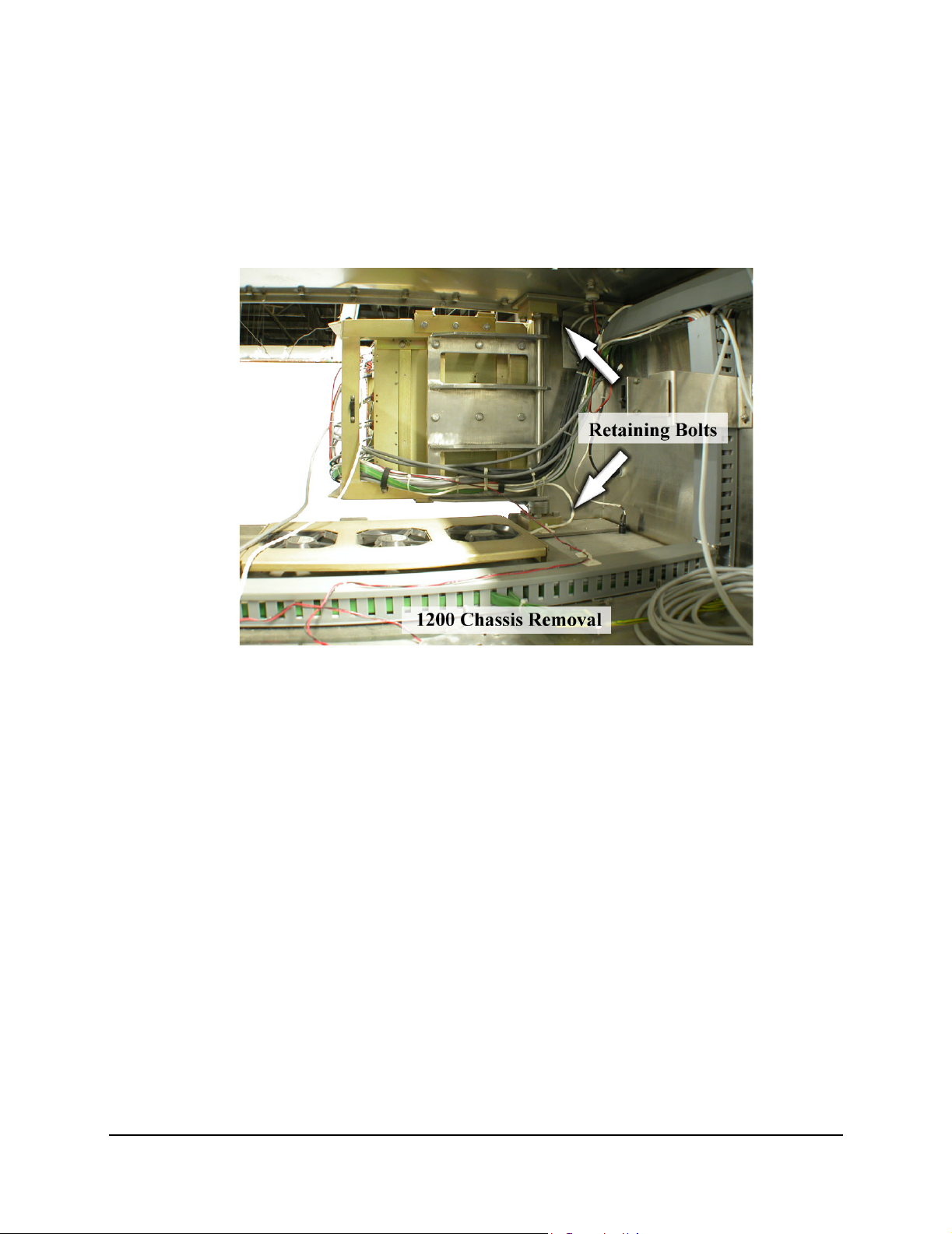
OV-900/1200 Series 3000 Upper Cabinet
Each of the electronics cages can be taken out of the system by
removing the retaining bolts from lower and upper brackets.
Retain all of the bolts from the chassis. These retaining bolts will
be used to secure portions of the upgrade.
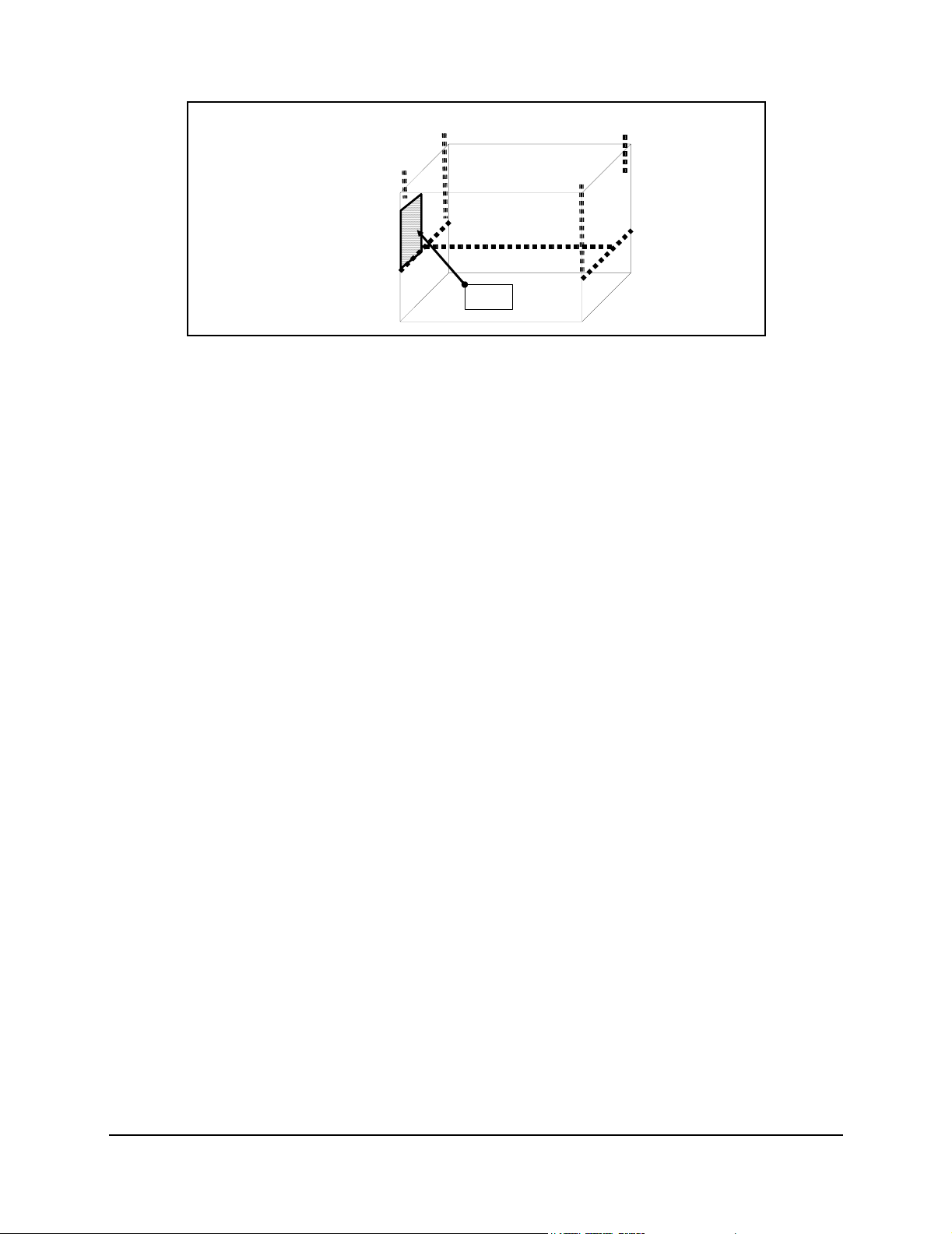
“Plate 2” Removal
Remove the plate inside the base cabinet. See the following
drawing for the location.
For OV900 Series 1000/2000 & all OV1200: Do not lose this plate.
Plate 2 will be used later in the upgrade.
For OV900: Instead of the plate pictured below, you will be using
the original plate that supported the PLC/Comm connector box.
This plate will be mounted directly below the existing K1/K2
plate. An additional mounting point will be required for this
plate. this can be accomplished by drilling a hole through the
Base Cabinet skin that aligns with the hole in the plate’s flange
located in the lower left side. Drill the hole using a #29 drill bit
and tap with an #8-32 tap.
Machine Preparation 9
Document 45277-0805
Red Harness
Yellow Column
White Column
BLUE COLUMN
Plate 2
Location

10 Omnivision Upgrade Installation Manual
Document 45277-0805
Junction Box Mounting (SB1 & SB3)
Parts/Kits Required:
• 45265, Kit, SB1 (Packed in Lower Cabinet Kit 45252)
• 45268, Kit, SB3 (Packed in Lower Cabinet Kit 45252)
To o l s r e q u i r e d :
• 7/16 Allen Wrench
• 13/64 drill bit
• 25/64 drill bit
• 3/4” Conduit Punch or 1 1/8” Punch
Parts required:
• Gasket (41204) (2)
• Assy, Junction, 8 port (40458) (2)
• 8-32 x 1 ¼ Socket Head Screw (2)
• 8-32 x 1 Socket Head Screw (4)
• #8 Flat Washer (10)
• #8 Lock Washer (16)
• 8-32 Nut (6)
Using the drill guide tool (45283) drill holes for SB1(45265) & SB3
(45268).
Note: When drilling the holes use cutting oil and low drill speeds. DO NOT TRY TO DRILL THE
HOLE AT HIGH SPEED. Stainless steel will expand if it gets hot and will bind the drill.
Use the 3/4 Conduit Punch or the 1 1/8” punch to enlarge the 3/8
hole to allow the cable to pass through the OV base cabinet wall.
Mount the SB1 sensor breakout box on the upstream panel and
the SB3 sensor breakout box on the downstream panel. (SB assy’s
Packed in Lower Cabinet Kit P/N 45252)

Junction Box Mounting (SB1 & SB3) 11
Document 45277-0805
Place a 41204 gasket underneath the junction box and use the
included screws to attach the junction box.
Placement on Base Cabinet Exterior
13/64 Drill (3x)
Drilling Guide
25/64 Drill
Alignment Pins
Upstream Side (SB1) Downstream Side (SB3)

12 Omnivision Upgrade Installation Manual
Document 45277-0805
Power Connections
The upgrade will require installation of a new power switch
(Packed in Lower Cabinet Kit P/N 45252). The power switch is
pre-wired and will have to connect to the motor starter and
transformers. Check the following table for the appropriate
drawing and refer to the corresponding drawing.
Power Switch
Route the corresponding wires (L1, L2 and L3) through the
existing conduit. These wires come in a sets of 2 each. One set of
wires will land on the motor starter
Depending on the base cabinet installation the wires that connect
to the primaries of the transformers may not be needed as these
wires are already present.
Power Harness Installation
AC Breaker and Motor Controller Panel
Parts needed:
• ¼-20 x ¾ Hex Head (7)
• ¼ Lock Washer (7)
• ¼ Flat Washer (7)
Tools needed:
• 7/16 hex nut driver
• flat head screw driver
The AC Breaker panel and Motor Controllers are located inside at
the lower cabinet as shown in the following figure.
Input Voltage New Drawing
220-240 VAC 43115
380-415 VAC 45242
This manual suits for next models
4
Table of contents
Other Filtec Industrial Equipment manuals


