Hix Halux 1200 User manual
16
WARRANTY
1201 E. 27th Terrace • Pittsburg, KS 66762 • U.S.A.
Web site: www.hixcorp.com • Phone: (800) 835-0606 • Fax: 620-231-1598
©2015 HIX Corp.
Design and Manufacturers of Graphic Imaging, Commercial Food, Industrial and Custom Drying Equipment
(Effective October 30, 2015)
HIX will automatically register the equipment on the date it was shipped to you or your distributor. If the
equipment was not purchased directly from HIX, but through a distributor (either domestic or foreign), please
keep a copy of their sales invoice showing the serial number and date it was sold/shipped to you with this war-
ranty. In this case, we will use the distributor’s invoice date as the beginning warranty date. STAPLE A COPY
OF YOUR RECEIPT TO THIS WARRANTY and keep in a safe place to provide verification of your warranty
should a problem occur. Thank you.
Please fill in the following information and attach a copy of your receipt for your records.
Date Purchased: From:
Model #: Serial #:
This warranty applies to equipment manufactured by the HIX Corporation (HIX), Pittsburg, Kansas, U.S.A.
HIX warrants to the original purchaser, its Ovens and Dryers, Heat Transfer Presses, Mug Presses, Mug Glazer,
Retensionable Screen Frames, Textile Printers, Spot Heaters, and Exposure Units against defects in workman-
ship and material, except for wear and tear for a period of “One Year” from the date of purchase. HIX warrants
its Accessories, Reten Splines/Hardware/Tool Kit, and Shuttle for a period of 90 days from the date of purchase.
Thermatrol and doughXpress products are covered under separate warranty.
In the event of a defect, HIX, at its option, will repair, replace or substitute the defective item at no cost during
this period subject to the limitations of insurance and shipping costs stated below.
In the case of heat transfer presses (except the Hobby Lite), HIX warrants the heat casting for the “Life” of the
machine for the original purchaser. If a part becomes obsolete at the time for repair, and/or cannot be reason-
ably substituted for, HIX will credit, at half the then current list price or last recorded price, only that part toward
a new machine or any product HIX offers. This credit offer shall be the sole responsibility of the HIX Corporation
in the event of an obsolete part.
This warranty does not cover belts, rail tape, pads, mug wraps, canvas, rubber blankets, bulbs, glass, rod
ends, turn buckles on printers or damages due to accident, misuse/abuse, alterations or damage due to neglect,
shipping or lack of proper lubrication or maintenance. HIX shall not be responsible for repairs or alterations
made by any person without the prior written authorization by HIX. This warranty is the sole and exclusive war-
ranty of HIX and no person, agent, distributor, or dealer of HIX is authorized to change, amend or modify the
terms set forth herein, in whole or in part.
In the case of a problem with the equipment identified herein, HIX Corporation should be contacted during
regular business hours to discuss the problem and verify an existing warranty. HIX personnel will assist the
customer to correct any problems which can be corrected through operation or maintenance instructions, simple
mechanical adjustments, or replacement of parts. In the event the problem cannot be corrected by phone, and
upon the issuance of a return authorization by HIX, the equipment shall be returned to HIX or an authorized
service representative. All insurance, packaging and shipment/freight costs are solely the responsibility of the
customer, and not that of HIX, and HIX shall not be responsible for improper packaging, handling or damage
in transit. Contact HIX customer service for complete return authorization information. Correct shipping boxes
are available from HIX.
This expressed warranty is given in lieu of any and all other warranties, whether expressed or implied, in-
cluding but not limited to those of merchantability and fitness for a particular purpose, and constitutes the only
warranty made by HIX Corporation.
In no event shall HIX’s liability for breach of warranty extend beyond the obligation to repair or replace the
nonconforming goods. HIX shall not be liable for any other damages, either incidental or consequential, or the
action as brought in contract, negligence or otherwise.
This warranty gives you specific legal rights and you may also have other rights which vary from state to
state.
Installation ........................................................................................................2
Initial Start Up...................................................................................................3
Exposing Screens.............................................................................................4
Determining Exposure Time / Chart ..............................................................5-6
Vacuum Switch Adjustment .............................................................................. 7
Glass Cleaning .................................................................................................8
Fan Filter Servicing...........................................................................................8
Lamp Replacement .....................................................................................8-10
Vacuum Pump Filter Replacement .................................................................10
Lid Realignment......................................................................................... 11-12
Blanket Replacement .....................................................................................12
Troubleshooting Charts .............................................................................13-14
Parts Identification.....................................................................................15-19
Warranty .........................................................................................................20
Halux 1200
Digital Hot Restrike Exposure Unit
OWNER’S MANUAL
CONTENTS
BEFORE warranty repair you MUST get Prior Authorization:
For Customer Service, Call 1-800-835-0606
or Visit www.hixcorp.com
70280 RV H_110115
NOTE:
Due to the unique
hot strike feature, the
Halux-1200D must be
supplied power by a
120V, 20 Amp dedicat-
ed circuit and constnt
voltage between 115-
125V.

2
RECEIVING & INSTALLATION
NOTE: The HIX Halux 1200D is not compatible with the M&R Trilok
pin registration system.
CAUTION: Before installing or operating this unit be sure to read
these instructions thoroughly. Disconnect all electric
power before performing maintenance on this unit. Never
operate this equipment with the power supply cover re-
moved. If you find that this should be necessary, contact
a licensed electrician. Make sure the circuit for this unit
is well grounded.
WARNING: ULTRA VIOLET LIGHT CAN CAUSE SKIN & EYE IR-
RATION OR BLINDNESS. TO PREVENT DAMAGE TO YOUR
EYES AND SKIN, AVOID DIRECT EXPOSURE TO THE LAMP
WHILE IT IS ON.
INSTALLATION
1. Carefully uncrate exposure unit from its shipping container.
2. Place exposure unit on a level surface close to the wall circuit to
be used. Adjust leveling feet, if necessary, so the unit does not
“rock” on the floor.
WARNING: When using an extension cord, use 12 ga.-3 conductor.
Maximum length, 25’ (7.62m).
3. Check unit over for any transportation damage and make sure all
foreign objects, such as packing material, have been removed.
Clean both sides of glass from any dust. (See page 8)
4. The vacuum hose is connected to the top frame by a small hose
clamp prior to shipping. Make sure the hose connection is still
in place and secure. If the hose seems loose or has come off
during shipping, secure hose and tighten hose clamp screw with
a small flat-head screwdriver.
15
TROUBLESHOOTING
PROBLEM
4. Lamp fails to remain
ignited.
5. Lamp ignites OK
when cold, but
will not HOT
Restrike reliably.
6. Unit fails to turn off
when the power
switch is “OFF”.
7. Blanket won’t “pull”
a vacuum.
POSSIBLE CAUSE
4. a. Lamp housing
cooling fan failure.
b. Obstruction of
air input or output
causing over heat-
ing, thus tripping the
thermostat.
c. Defective high
limit thermostat.
5. Low voltage supply.
Must be 115-120v
on a 120v unit or
230-240v on a 230v
unit. Voltage mea-
sured must be when
unit is on and under
load.
6. Power switch is
shorted.
7. Vacuum leak.
REMEDY
4. a. Replace cooling
fan.
b. Remove obstruc-
tion, allow thermo-
stat to cool, it will
then reset itself.
c.Replace thermo-
stat.
5. Have a electrician
remedy the cause of
low voltage supply
to the unit.
6. Replace power
switch.
7 a. Check hose con-
nections to vacuum
pump and to blanket
frame.
b. Check gasket to
glass seal, replace if
necessary.
c. Realign lid.
d. Check vacuum
pump.

14
TROUBLESHOOTING
PROBLEM
1. Lamp does not ig-
nite and red light on
main power switch
is off.
2. Lamp does not ig-
nite and red light on
main power switch
is on.
3. Unit blows fuses or
trips Main Power
Circuit Breaker.
POSSIBLE CAUSE
1. a. No line power.
b. Supply fuse or
breaker blown.
c. Unit main breaker
is tripped.
d. Main power
switch is defective.
e. Outlet is defec-
tive.
2. a. Vacuum is off.
b. Vacuum blanket
is not pulling down
tightly.
c. Vacuum switch is
out of adjustment.
d. Ignitor is bad.
e. Lamp is burned
out.
3. a. Check amperage
of supply breakers
or fuses.
b. Shorted
capacitor(s). Discol-
ored or inflated.
c. Shorted ballast.
REMEDY
1. a. Check power
source.
b. Reset supply
breaker or replace
fuse.
c. Reset unit’s main
breaker.
d. Replace switch.
e. Replace outlet.
2. a. Turn vacuum on.
b. Determine source
of vacuum leak and
repair.
c. Adjust vacuum
switch.
d. Replace ignitor.
e. Replace lamp.
3. a. Replace supply
breakers or fuses
with minimum rating
of 20 amps.
b. Replace capaci-
tors.
c. Replace ballast.
3
INITIAL SETUP
The “hot Restrike” feature, eliminates warming times between ex-
posure, saving electricity and extending bulb life. Due to this unique
Hot Strike feature, the Halux-1200D must be supplied electrical
power by a 120 volt, 20 amp dedicated circuit and constant voltage
between 115-125 volts.
The Hot Restrike System provides the advantage of a simple ex-
tremely reliable system with no moving parts, however some con-
sideration must be made to ensure consistent screen exposures.
From a “Cold” start (e.g. first screen to be exposed for the day) the
lamp requires a 1 minute warm up cycle to bring the lamp to full
intensity. Also if more than 90 seconds elapses between screen
exposures, then the lamp should be cycled on for a minute to ensure
full intensity of the lamp for consistent screen exposures.
To warm up the lamp before starting your first exposure, follow this
procedure.
1. Plug in your unit to the proper voltage power source (120V or
230V) as indicated on the serial number I.D. tag. NOTE: Ade-
quate voltage is required for proper operation. A minimum of
115V on a 120V circuit is required. The 230V version requires
a full 230 volts to operate properly. If voltage drops below
required level unit will not re-light. Simply wait 2 minutes to
cool and restart.
2. Close the blanket lid and latch the lid shut with the rubber latch-
hooks.
3. Turn the Main Power switch “ON”.
4. Turn the Vacuum switch “ON” and allow the blanket to pull down
tight to the glass.
5. Set the timer on at least 1 minute and press the “Start” button. To
change the time setting - see detailed instructions below.
6. The lamp will illuminate and quickly increase in intensity. When
the time set on the timer reaches “0” the lamp will extinguish.
Turn the vacuum switch off and release the blanket lid.
7. Within 90 seconds place the first emulsion coated screen frame
into the unit, as detailed on the next page, and start an exposure.

4
OPERATION
DIGITAL TIMER
1. Turn Main Power “On”. Timer will illuminate.
2. To change time setting, press the button on the front of the
timer face. Timer will display “Minutes” and “Seconds”.
3. To program the desired time (minutes and seconds), press the
button; once for each digit. The counter will loop from 0-9.
To change to the next digit, press the button and again
press the button until the desired number is reached.
4. Once the new time is entered, press the “MD” button on the
face of the timer to lock in this new setting. Failure to press
the “MD” button will not “lock” in the new setting.
5. Press the “Start” button on the control panel. This will start the
timer and turn the exposure lamp on.
6. Timer will count down and when time reaches zero, the expo-
sure lamp will extinguish.
7. If at any time you want to extinguish the exposure lamp before
time expires, you may do so by pressing the “RST” button on
the face of the timer.
13
REPAIRS
7. Retighten the 1/4” allen screws on the hinge bracket at the back
of the unit.
8. Turn off the vacuum and allow it to stabilize.
9. Carefully lift the lid to the open position and push the end of the
gas spring back onto the ball connector.
10. Check operation, repeat alignment procedure if necessary.
11. Replace the plastic gas spring end covers and recheck for proper
operation.
BLANKET REPLACEMENT
NOTE: If the blanket fails to pull a vacuum, check the Troubleshooting
Chart for possible causes. If you determine that your blanket
has begun to leak, it needs to be replaced. New blanket re-
placement kit can be ordered from HIX Corporation by call-
ing Customer Service at 800-835-0606. Refer to Customer
Service sheet CS-170.
12
MAINTENANCE
LID REALIGNMENT
NOTE: The light and vacuum are sealed under the lid by means of
rubber gasket on the underside the lid frame. This rubber
gasket may compress over time. If light is seen from the
sides of the unit, or if the vacuum does not occur, the rubber
gasket may be compressed or the lid is out of alignment.
These problems can be alleviated by realigning the hinges.
1. Begin with the lid in the open position. Remove the plastic cap
from the lid end of one of the gas springs. While holding the lid,
pull end of gas spring straight out and off of the ball connector
as you continue to manually hold the lid up.
CAUTION:It is important to do this operation with the lid up, failing
to do so could cause injury due to the sudden release of
pressure on the gas spring!
2. Gently lay lid back down onto the glass and turn on the vacuum
switch.
3. Loosen 1/4” Allen-head capscrews on the side of the exposure
unit (2 on each side). (See figure above)
4. Loosen 1/4” Allen-head capscrews from the back of exposure
unit. (2 on each side).
5. The vacuum pull will self align the hinges.
6. With the vacuum still applied, retighten the 1/4” allen screws at
the sides of the unit.
Gas Spring and
Plastic Cap
1/4” Allen-head
Capscrews
1/4” Allen-head
Capscrews
5
EXPOSING
EXPOSING A SCREEN
Maximum screen sizes:
One 24” x 42” or Two 21” x 24”
NOTE: Put the screen in the center of the glass. Keep at least 2”
from any edge of the glass to prevent damage to the vacuum
blanket rubber.
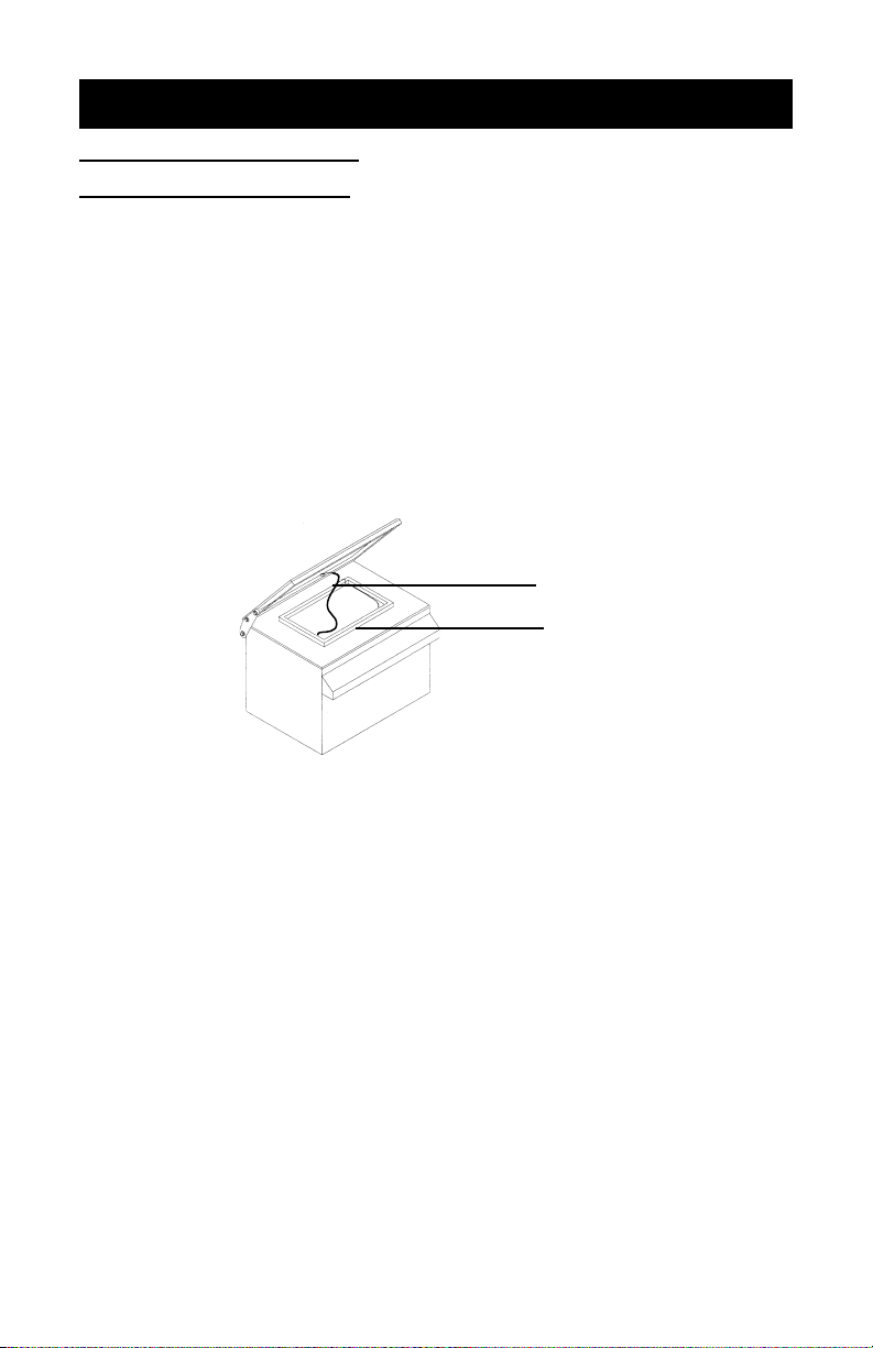
1. Place your screen frame in the center of the glass, screen side
down with your output image in place.
2. Place bleeder cord on top of and inside the frame and across the
image. (See illustration below) NOTE: This cord facilitates quick
blanket draw down and releasing of the vacuum after exposure
and the vacuum has been turned off.
3. Close the blanket lid and latch the lid shut.
4. Turn the Main Power switch “ON”.
5. Turn the Vacuum switch “ON” and allow the blanket to pull down
tight to the screen and the glass.
6. Set the timer on the desired exposure time for the type of emul-
sion and screen you are going to expose. See “Determining
Your Optimum Exposure Time” on page 6 or your filled in chart
on page 7 if you have already determined your exposure time.
7. Press the “Start” button located to the right of the timer dial to
begin the exposure.
8. At the end of the selected time, the lamp will extinguish.
9. Turn the vacuum switch off, release and open the lid and remove
the screen frame. If another screen is to be exposed, do this within
90 seconds or a brief warm up of the lamp will be necessary as
described in the “Initial Startup” instructions on page 3.
Bleeder Cord
Screen
Table of contents
Other Hix Industrial Equipment manuals


