Filtec FT-50 User manual

FT-50 Fill Level
Inspector
Operation Guide
Document 40272-0700

FT-50 Fill Level Inspector
Operation Guide
Document 40272-0700

Industrial Dynamics Company, Ltd.
Document 40272-0700 Copyright. All rights reserved.
No part of this publication may be reproduced or used in any form or by any means (graphic,
electronic, or mechanical including photocopying, recording, taping, or information storage
and retrieval system) without written permission of Industrial Dynamics Company, Ltd.
Filtecand Industrial Dynamicsare registered trademarks of Industrial Dynamics Company,
Ltd. All other trademarks are the property of their respective owners.
Contact Information
Corporate Headquarters: 3100 Fujita Street,
Torrance, California
90505-4007
U.S.A.
Telephone:(310) 325-5633
FAX: (310) 530-1000
Internet: www.filtec.com
Mailing Address: P.O. Box 2945,
Torrance, California
90509-2945
U.S.A.
Shipping Address: 3100 Fujita Street,
Torrance, California
90505-4007
U.S.A.
Customer Service: (800) 733-5173

Table of Contents i
Document 40272-0700
Table of Contents
Radiological Safety Information
Understanding Radiological Safety . . . . . . . . . . . . . . . . . . . . . . . . . . . . . . . . v
Radiological Safety Guidelines. . . . . . . . . . . . . . . . . . . . . . . . . . . . . . . . . . vi
Radiation Measurement Testing Data . . . . . . . . . . . . . . . . . . . . . . . . . . . . . vii
Radiation Warning Labels . . . . . . . . . . . . . . . . . . . . . . . . . . . . . . . . . . . . . viii
Filtec Model FT-50 Radiation Exposure Profiles . . . . . . . . . . . . . . . . . . . . . . ix
Chapter 1: FT-50 System Overview
Inspection System Description. . . . . . . . . . . . . . . . . . . . . . . . . . . . . . . . . . . . . . . 1-2
Fill Level Inspection Basics . . . . . . . . . . . . . . . . . . . . . . . . . . . . . . . . . . . . 1-3
Rejection Control Basics. . . . . . . . . . . . . . . . . . . . . . . . . . . . . . . . . . . . . . 1-4
Optional System Features. . . . . . . . . . . . . . . . . . . . . . . . . . . . . . . . . . . . . . . . . . 1-5
High Cap/Bulged Can Detection . . . . . . . . . . . . . . . . . . . . . . . . . . . . . 1-5
Missing Cap/Missing Lid Detection . . . . . . . . . . . . . . . . . . . . . . . . . . . 1-5
Dud Detection . . . . . . . . . . . . . . . . . . . . . . . . . . . . . . . . . . . . . . . . 1-5
Low Foam Detection . . . . . . . . . . . . . . . . . . . . . . . . . . . . . . . . . . . . 1-6
Foil Seal Detection . . . . . . . . . . . . . . . . . . . . . . . . . . . . . . . . . . . . . 1-6
Smashed Container Detection . . . . . . . . . . . . . . . . . . . . . . . . . . . . . . 1-6
Down Can Detection . . . . . . . . . . . . . . . . . . . . . . . . . . . . . . . . . . . . 1-6
Label Inspection . . . . . . . . . . . . . . . . . . . . . . . . . . . . . . . . . . . . . . . 1-6
Reject Sorting . . . . . . . . . . . . . . . . . . . . . . . . . . . . . . . . . . . . . . . . 1-6
Serial Interface. . . . . . . . . . . . . . . . . . . . . . . . . . . . . . . . . . . . . . . . 1-6
Programmable Logic Controller Interface (PLC) . . . . . . . . . . . . . . . . . . 1-6
Chapter 2: Operating Your FT-50
Starting-Up Your FT-50 . . . . . . . . . . . . . . . . . . . . . . . . . . . . . . . . . . . . . . . . . . . . 2-2
The Safety Shutter . . . . . . . . . . . . . . . . . . . . . . . . . . . . . . . . . . . . . . . . . . . . . . 2-3
Operating the Manual Safety Shutter . . . . . . . . . . . . . . . . . . . . . . . . . . . . . 2-3
Container Changeover . . . . . . . . . . . . . . . . . . . . . . . . . . . . . . . . . . . . . . . . . . . . 2-4
Selecting the Container Type to be Inspected. . . . . . . . . . . . . . . . . . . . . . . . 2-4
Adjusting the Inspection Head Height . . . . . . . . . . . . . . . . . . . . . . . . . . . . . 2-5
Adjusting the Conveyor Guide Rails . . . . . . . . . . . . . . . . . . . . . . . . . . . . . . 2-6
Adjusting the Centerline Trigger Bracket Height . . . . . . . . . . . . . . . . . . . . . . 2-7
Adjusting Optional Sensors and Sensor Brackets . . . . . . . . . . . . . . . . . . . . . . 2-8
Aligning the Missing Cap Sensor . . . . . . . . . . . . . . . . . . . . . . . . . . . . . . . . . 2-9
Aligning the High Cap Sensor . . . . . . . . . . . . . . . . . . . . . . . . . . . . . . . . . 2-11
Aligning the Smashed Bottle Sensor . . . . . . . . . . . . . . . . . . . . . . . . . . . . . 2-13

ii FT-50 Fill Level Inspector
Document 40272-0700
Aligning the Inspection Trigger (Bottles) . . . . . . . . . . . . . . . . . . . . . . . . . . 2-15
Aligning the Missing Lid Sensor . . . . . . . . . . . . . . . . . . . . . . . . . . . . . . . . 2-17
Aligning the Bulged Can Sensor . . . . . . . . . . . . . . . . . . . . . . . . . . . . . . . . 2-19
Aligning the Down Can Sensor . . . . . . . . . . . . . . . . . . . . . . . . . . . . . . . . 2-21
Aligning the Inspection Trigger (Cans) . . . . . . . . . . . . . . . . . . . . . . . . . . . 2-22
Chapter 3: Using the System Software
The Operator Control Panel . . . . . . . . . . . . . . . . . . . . . . . . . . . . . . . . . . . . . . . . 3-2
Software Function Groups . . . . . . . . . . . . . . . . . . . . . . . . . . . . . . . . . . . . . . . . . 3-3
The Function Keys. . . . . . . . . . . . . . . . . . . . . . . . . . . . . . . . . . . . . . 3-3
The Arrow Keys. . . . . . . . . . . . . . . . . . . . . . . . . . . . . . . . . . . . . . . . 3-3
Software Functions List . . . . . . . . . . . . . . . . . . . . . . . . . . . . . . . . . . . . . . . . . . . 3-4
Software Function Descriptions . . . . . . . . . . . . . . . . . . . . . . . . . . . . . . . . . . . . . . 3-7
Fill Level Functions Group . . . . . . . . . . . . . . . . . . . . . . . . . . . . . . . . 3-7
Container Finish Functions Group. . . . . . . . . . . . . . . . . . . . . . . . . . . . 3-7
Rejector Functions Group . . . . . . . . . . . . . . . . . . . . . . . . . . . . . . . . 3-10
System Functions Group . . . . . . . . . . . . . . . . . . . . . . . . . . . . . . . . . 3-11
Diagnostics Function Group. . . . . . . . . . . . . . . . . . . . . . . . . . . . . . . 3-12
Chapter 4: Diagnostics and Troubleshooting
Diagnostic Errors . . . . . . . . . . . . . . . . . . . . . . . . . . . . . . . . . . . . . . . . . . . . . . . 4-2
Diagnostic Error Codes Listing . . . . . . . . . . . . . . . . . . . . . . . . . . . . . . . . . . 4-2
Diagnostic Error Descriptions . . . . . . . . . . . . . . . . . . . . . . . . . . . . . . . . . . 4-4
Error Number 2. . . . . . . . . . . . . . . . . . . . . . . . . . . . . . . . . . . . . . . . 4-4
Error Number 5. . . . . . . . . . . . . . . . . . . . . . . . . . . . . . . . . . . . . . . . 4-4
Error Number 6. . . . . . . . . . . . . . . . . . . . . . . . . . . . . . . . . . . . . . . . 4-4
Error Number 10 . . . . . . . . . . . . . . . . . . . . . . . . . . . . . . . . . . . . . . . 4-4
Error Number 11 . . . . . . . . . . . . . . . . . . . . . . . . . . . . . . . . . . . . . . . 4-4
Error Number 12 . . . . . . . . . . . . . . . . . . . . . . . . . . . . . . . . . . . . . . . 4-4
Error Number 13 . . . . . . . . . . . . . . . . . . . . . . . . . . . . . . . . . . . . . . . 4-4
Error Number 14 . . . . . . . . . . . . . . . . . . . . . . . . . . . . . . . . . . . . . . . 4-5
Error Number 15 . . . . . . . . . . . . . . . . . . . . . . . . . . . . . . . . . . . . . . . 4-5
Error Number 16 . . . . . . . . . . . . . . . . . . . . . . . . . . . . . . . . . . . . . . . 4-5
Error Number 22 . . . . . . . . . . . . . . . . . . . . . . . . . . . . . . . . . . . . . . . 4-5
Error Number 23 . . . . . . . . . . . . . . . . . . . . . . . . . . . . . . . . . . . . . . . 4-5
Error Number 24 . . . . . . . . . . . . . . . . . . . . . . . . . . . . . . . . . . . . . . . 4-5
Error Number 25 . . . . . . . . . . . . . . . . . . . . . . . . . . . . . . . . . . . . . . . 4-5
Error Number 27 . . . . . . . . . . . . . . . . . . . . . . . . . . . . . . . . . . . . . . . 4-5
Error Number 33 . . . . . . . . . . . . . . . . . . . . . . . . . . . . . . . . . . . . . . . 4-6
Error Number 34 . . . . . . . . . . . . . . . . . . . . . . . . . . . . . . . . . . . . . . . 4-6
Error Number 46 . . . . . . . . . . . . . . . . . . . . . . . . . . . . . . . . . . . . . . . 4-6

Table of Contents iii
Document 40272-0700
Error Number 47 . . . . . . . . . . . . . . . . . . . . . . . . . . . . . . . . . . . . . . . 4-6
Error Number 48 . . . . . . . . . . . . . . . . . . . . . . . . . . . . . . . . . . . . . . . 4-6
Error Number 49 . . . . . . . . . . . . . . . . . . . . . . . . . . . . . . . . . . . . . . . 4-6
Error Number 50 . . . . . . . . . . . . . . . . . . . . . . . . . . . . . . . . . . . . . . . 4-6
Error Number 51 . . . . . . . . . . . . . . . . . . . . . . . . . . . . . . . . . . . . . . . 4-7
Error Number 52 . . . . . . . . . . . . . . . . . . . . . . . . . . . . . . . . . . . . . . . 4-7
Error Number 53 . . . . . . . . . . . . . . . . . . . . . . . . . . . . . . . . . . . . . . . 4-7
Error Number 54 . . . . . . . . . . . . . . . . . . . . . . . . . . . . . . . . . . . . . . . 4-7
Error Number 58 . . . . . . . . . . . . . . . . . . . . . . . . . . . . . . . . . . . . . . . 4-7
Error Number 61 . . . . . . . . . . . . . . . . . . . . . . . . . . . . . . . . . . . . . . . 4-7
Error Number 66 . . . . . . . . . . . . . . . . . . . . . . . . . . . . . . . . . . . . . . . 4-7
Error Number 67 . . . . . . . . . . . . . . . . . . . . . . . . . . . . . . . . . . . . . . . 4-8
Error Number 68 . . . . . . . . . . . . . . . . . . . . . . . . . . . . . . . . . . . . . . . 4-8
Error Number 72 . . . . . . . . . . . . . . . . . . . . . . . . . . . . . . . . . . . . . . . 4-8
Error Number 86 . . . . . . . . . . . . . . . . . . . . . . . . . . . . . . . . . . . . . . . 4-8
Error Number 117 . . . . . . . . . . . . . . . . . . . . . . . . . . . . . . . . . . . . . . 4-8
Error Number 118 . . . . . . . . . . . . . . . . . . . . . . . . . . . . . . . . . . . . . . 4-8
Error Number 119 . . . . . . . . . . . . . . . . . . . . . . . . . . . . . . . . . . . . . . 4-8
Error Number 120 . . . . . . . . . . . . . . . . . . . . . . . . . . . . . . . . . . . . . . 4-9
Error Number 121 . . . . . . . . . . . . . . . . . . . . . . . . . . . . . . . . . . . . . . 4-9
Troubleshooting Procedures . . . . . . . . . . . . . . . . . . . . . . . . . . . . . . . . . . . . . . . 4-10
Is the power turned on. . . . . . . . . . . . . . . . . . . . . . . . . . . . . . . . . . 4-10
Is the power filter circuit breaker tripped . . . . . . . . . . . . . . . . . . . . . 4-10
Is the Safety Shutter Opened. . . . . . . . . . . . . . . . . . . . . . . . . . . . . . 4-10
The display does not respond when keys are pressed . . . . . . . . . . . . . . 4-10
The display shows a blinking cursor and the beacon is on . . . . . . . . . . . 4-11
There is no display and the beacon is off. . . . . . . . . . . . . . . . . . . . . . 4-11
The display is garbled or operates erratically . . . . . . . . . . . . . . . . . . . 4-11
False triggers or reject timing malfunctions are occurring . . . . . . . . . . 4-11
No triggering occurs . . . . . . . . . . . . . . . . . . . . . . . . . . . . . . . . . . . 4-11
The rejector does not function . . . . . . . . . . . . . . . . . . . . . . . . . . . . 4-12
All containers are rejected . . . . . . . . . . . . . . . . . . . . . . . . . . . . . . . 4-12
The rejector is operating erratically . . . . . . . . . . . . . . . . . . . . . . . . . 4-12
The rejector arm is sticking or binding . . . . . . . . . . . . . . . . . . . . . . . 4-12
The rejector arm remains extended . . . . . . . . . . . . . . . . . . . . . . . . . 4-13
Rejected container trajectory is sloppy or inconsistent . . . . . . . . . . . . 4-13

iv FT-50 Fill Level Inspector
Document 40272-0700
Chapter 5: Maintenance Procedures
Maintenance Schedules . . . . . . . . . . . . . . . . . . . . . . . . . . . . . . . . . . . . . . . . . . . 5-2
Daily Maintenance. . . . . . . . . . . . . . . . . . . . . . . . . . . . . . . . . . . . . . 5-2
Weekly Maintenance . . . . . . . . . . . . . . . . . . . . . . . . . . . . . . . . . . . . 5-2
Monthly Maintenance. . . . . . . . . . . . . . . . . . . . . . . . . . . . . . . . . . . . 5-2
120 Day Maintenance . . . . . . . . . . . . . . . . . . . . . . . . . . . . . . . . . . . . 5-3
Maintenance Procedures . . . . . . . . . . . . . . . . . . . . . . . . . . . . . . . . . . . . . . . . . . 5-4
Trigger Beam and Emitter Lenses . . . . . . . . . . . . . . . . . . . . . . . . . . . . 5-4
High Cap, Missing Cap, and Smashed Bottle Sensors. . . . . . . . . . . . . . . . 5-4
The FT-50 Housing. . . . . . . . . . . . . . . . . . . . . . . . . . . . . . . . . . . . . . 5-5
Pressure Regulator and Air Filter . . . . . . . . . . . . . . . . . . . . . . . . . . . . 5-5
External Wiring. . . . . . . . . . . . . . . . . . . . . . . . . . . . . . . . . . . . . . . . 5-5
Replacing the Rejector Pad . . . . . . . . . . . . . . . . . . . . . . . . . . . . . . . . 5-5
Servicing the Regulator and Coalescing Air Filters . . . . . . . . . . . . . . . . . 5-5
Documentation Feedback
Documentation Feedback Form . . . . . . . . . . . . . . . . . . . . . . . . . . . . . . . . . . . . . FB-2

Radiological Safety Information v
Document 40272-0700
Radiological Safety Information
This section provides information about radiation, radiation safety proce-
dures, radiation certifications, and the radiation characteristics of the
FT- 50.
Understanding Radiological Safety
The Filtec FT-50 utilizes a small quantity of the radioisotope
Americium-241 to produce low level gamma radiation. The
Americium-241 is in ceramic enamel form and its melting range is in the
region of 900 degrees to 1050 degrees centigrade.
The Americium-241 is sealed inside a special type 304 stainless steel
capsule that is double fusion welded. This capsule is mounted in a
stainless steel enclosure inside the FT-50 Inspection Head.
A Radiation Safety Shutter, when opened, permits a narrow beam of
radiation to pass through the plastic radiation window in the enclosure.
When the safety shutter is closed all radiation is contained within the
source enclosure.
There are two possible ways to be exposed to hazardous levels of radio-
active material using this equipment: externally, through excessive
exposure to a radiation source outside the body, and internally by
ingesting radioactive material.
The FT-50 is unlikely to create hazardous radiation levels for the
following reasons:
• The FT-50’s radiation source produces a relatively weak source of
low energy (low penetrating power) gamma radiation. To receive a
hazardous dose of radiation from this low energy source would
require extremely long exposure directly to the main radiation beam.
• While we warn against placing hands or other body parts in front of
the gamma beam when it is turned on, it would require several hours
of exposure for the hand to receive an excessive radiation dose.
• The gamma beam is tightly confined by shields and collimators and is
completely contained within the inspection tunnel. Because the
radiation beam does not spread outside the inspection tunnel, it is
highly unlikely that under normal circumstances an appreciable
radiation dose could be incurred at a location other than directly in
front of the main gamma beam when the safety shutter is opened.

vi FT-50 Fill Level Inspector
Document 40272-0700
• The radioactive material is sealed by double fusion welds into a
stainless steel capsule. At manufacture, and again at installation, this
capsule is subjected to rigorous tests capable of detecting the leakage
of five millionths of one percent of the contents. Therefore as long as
the source capsule’s integrity is not compromised, radioactive
material cannot be released.
• As an additional precaution, the regulatory agencies require that a
licensed individual inspect the radiation source and the shutter
mechanism and conduct a leak test every 36 months.
Radiological Safety Guidelines
You have been supplied with a copy of the Rules, Regulations and Regis-
tration Requirements for your location, however, the following is a brief
synopsis of the general requirements.
1. Understand the rules, regulations, and registration requirements
regarding the use of this equipment at your location. A copy of this is
supplied with your FT-50.
2. Do not open or tamper with the enclosure containing the radioisotope
source.
3. Do not place your hands, or any other body part, between the source
and detector when the safety shutter is open.
4. Have inspection and wipe tests performed by a properly licensed
technician at the specified 36 month intervals (Industrial Dynamics'
Service Technicians can do this). Keep a record of each inspection
and test.
5. In the case of an accident which crushes or punctures the source
enclosure, seal off the area, cover the FT-50 and surroundings with a
plastic sheet or tarpaulin and call Industrial Dynamics immediately.
6. Do not relocate or dispose of the FT-50 without proper approval. A
licensed technician must perform this function.
7. If you have any questions, call Industrial Dynamics.

Radiological Safety Information vii
Document 40272-0700
Radiation Measurement Testing Data
1. All measurements were taken with Technical Associates Model Pug-1
survey meter. The meter was cross calibrated against an air ionization
chamber survey meter whose response was corrected against an
Americium-241 test source.
2. Source Shutter closed - The radiation levels are less than 0.05
MR/HR at distances greater than 5 cm from any surface of the gauge
(including inside the tunnel).
3. Source Shutter open - The extent of the main gamma beam is
completely contained within the tunnel formed by the inspection head
and shielding bar. All radiation levels outside the main beam are less
than 0.05 MR/HR.
4. The exposure rate in the main beam is measured to be approximately
60 MR/HR at 5 cm from source enclosure containing 300 millicuries.

viii FT-50 Fill Level Inspector
Document 40272-0700
Radiation Warning Labels
Figure 1. The Safety labels attached to the FT-50 provide very important safety information and should be
followed explicitly.
SOURCE
MATERIAL - AMERICIUM 241
CAUTION
RADIOACTIVE MATERIAL
SEE INSTRUCTION MANUAL BEFORE
ATTEMPTING TO OPERATE, REPAIR,
CLEAN OR MOVE THIS DEVICE.
mCi DATE OF MFR.
REMOVAL OF THIS LABEL IS
PROHIBITED.
INDUSTRIAL DYNAMICS
TORRANCE, CALIFORNIA
AMOUNT mCi Bq
N O T I C E
"The receipt, possession, use, and transfer of this
device are subject to a general license or
equivalent and the regulations of the U.S. NRC or
of a state with which the NRC has entered into an
agreement for the exercise of regulatory authority."
This device shall not be transferred, abandoned, or
disposed of except by transfer to a person holding
a specific radioactive material license to receive
this device.
"Operation of this device shall be immediately
suspended until necessary repairs have been made
if there is any indication of possible failure or
damage to the shielding or containment of
radioactive material, or the ON-OFF mechanism
and indicator at intervals not to exceed three
years."
"This device shall be tested for proper operation of
the ON-OFF mechanism or indicator."
"The sealed radioactive source contained in this
cevice shall be tested at installation and every
three years thereafter for leakage of radioactive
material."
"Maintenance, tests, or other service involving the
radioactive material, its shielding and containment
shall be performed by persons holding a specific
radioactive material license to provide these
services."
"Installation, relocation, maintenance, repair, and
initial radiation survey of this device and leak
testing, installation, replacement, and disposal of
sealed sources containing radioactive material used
in this device shall be performed only by persons
holding a specific radioactive material license to
provide these services.
Industrial Dynamics Co., Ltd.
2927 Lomita Boulevard
Torrance, California 90509
(310)325-5633
REMOVAL OF THIS LABEL IS PROHIBITED.
Serial No. _______________
Model No. __________________________________
DO NOT PLACE HANDS OR ANY
PORTION OF THE BODY BETWEEN
THE RADIOISOTOPE SOURCE AND
DETECTOR, WHEN THE GAMMA BEAM
IS ACTIVATED. CLOSE SHUTTER
WHEN REPAIRING OR MAINTAINING
THE MACHINE.
?
6
4
3
5
1
2
?
6
4
35
1
2
Radiological Safety Information ix
Document 40272-0700
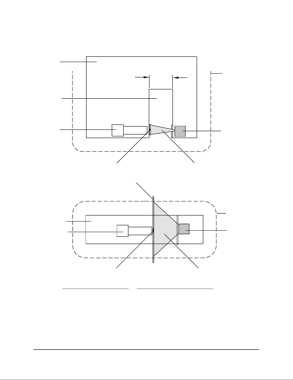
Filtec Model FT-50 Radiation Exposure Profiles
Gamma Gauge: 100 or 300 mCi Source
Figure 2. FT-50 Radiation Profile Schematic.
4" TO
7.5
"
1
1
2
3
3
4
4
5
5
6
6
7
7&8
8
No. Description No. Description
1 Inspection Head 5 5 cm Isodistance Contour
2 Inspection Tunnel 6 Radiation Detector
3 Sealed Americium-241 7 Shielding Bar (1/4” Thick Steel)
4 Limits of Main Beam 8 Detector Window

xFT-50 Fill Level Inspector
Document 40272-0700

Chapter 1: FT-50 System Overview
Industrial Dynamics Company, Ltd. Document 40272-0700 1-1
Chapter 1:
FT-50 System Overview

FT-50 Fill Level Inspector Operation Guide
1-2 Industrial Dynamics Company, Ltd. Document 40272-0700
Inspection System Description
This manual provides operator’s information about the FT-50 Fill Level
Inspection System. Unless specifically indicted otherwise, this manual
refers to both bottle and can versions.
The FT-50 provides high speed overfill or underfill (not concurrent) fill
level container inspection. Additional inspection options, such as missing
cap detection, missing label detection, and smashed bottle detection, may
be added to the FT-50 to enhance its functionality. For more information
see “Optional System Features” on page 2-5.
Figure 1-1. The FT-50 Fill Level Inspector.

Chapter 1: FT-50 System Overview
Industrial Dynamics Company, Ltd. Document 40272-0700 1-3
Fill Level Inspection Basics
The FT-50 Fill Level Inspection systems utilizes a Container Radiation
Profile Comparison Principle to create a radiation fingerprint of the
container.
To create a radiation profile a gamma beam is directed through the
container. Some of the radiation is blocked by the container material and
container’s contents while the remaining gammas emerge from the
opposite side of the container where they are measured by an gamma
detector.
The amount of radiation measured is the containers radiation profile, or
fingerprint, which is then compared against a Master Container Profile.
Figure 1-2. Scanning the container.
To allow for slight variances in the fill level an underfill threshold or
overfill threshold is determined. These thresholds form the tolerance
range for deviation from the master profile. Any container with a gamma
count above the underfill threshold (higher gamma counts indicate there
is less product to absorb the gamma beam) is rejected as an underfill. Any
container with a gamma count below the overfill threshold (lower gamma
counts indicate there is more product to absorb the gamma beam) is
rejected as an overfill.
?
6
INDUSTRIAL DYNAMICS
Torrance, California USA
MODEL FT-50
FILL LEVEL INSPECTOR
4
35
1
2
1
32
No. Description
1 gamma Source
2 gamma Beam
3gammaDetector
FT-50 Fill Level Inspector Operation Guide
1-4 Industrial Dynamics Company, Ltd. Document 40272-0700
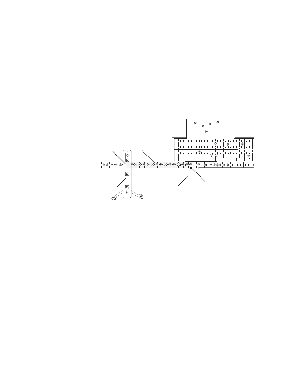
Rejection Control Basics
The FT-50 identifies and then tracks any container that fails inspection.
Tracking begins the moment the container crosses the inspection trigger
beam in the and ends when the container reaches the rejector centerline.
Figure 1-3. Tracking containers that fail inspection.
To maintain container tracking and to synchronize the rejector to the
conveyor, the FT-50 uses a high-resolution encoder coupled directly to the
conveyor drive sprocket. The encoder sends timing pulses to the FT-50
which uses the pulses to determine the container’s position as it moves
along the conveyor between the FT-50 and the rejector. When the
container reaches the rejector centerline the FT-50 emits a reject signal
which activates the rejector and removes the container from the
production line.
1
23
54
X
No. Description
1FT-50
2 Inspection Trigger Location
3 Extent of Tracking Area (gray)
4 Rejector Centerline
5 Rejector

Chapter 1: FT-50 System Overview
Industrial Dynamics Company, Ltd. Document 40272-0700 1-5
Optional System Features
The FT-50’s expandability allows you to add additional inspection
capabilities to match your production requirements. Depending upon the
FT-50 configuration you ordered, your unit may contain some of the
following features:
• High Cap/Bulged Can Detection
• Missing Cap/ Missing Lid Detection
• Dud Detection (High and Low Container Pressure)
• Smashed Bottle Detection
• Down Can Detection
• Low Foam Detection
• Foil Seal Detection
• Label Inspection
• Reject Sorting (Servotec only)
• External Reject Control
• Serial Controller Interface (Modbus or IDC Protocols)
• Programmable Logic Controller Interface (PLC)
Note
If you are unsure which options your unit contains, contact your Service
Department for information.
High Cap/Bulged Can Detection
This feature utilizes an optical sensor detect improperly seated caps on
bottles or bulged lids on cans.
Missing Cap/Missing Lid Detection
This feature detects the presence or absence of the container cap (bottle)
or lid (can). It is compatible with either plastic or metal caps and lids.
Dud Detection
This feature detects improper pressurization of vacuum sealed or pressure
sealed containers.

FT-50 Fill Level Inspector Operation Guide
1-6 Industrial Dynamics Company, Ltd. Document 40272-0700
Low Foam Detection
This feature uses a optical sensor to detect a low foam condition within
the container. This option is only available for clear containers.
Foil Seal Detection
This feature uses a proximity sensor to detect a foil seal under the
container cap. This option is available only for containers with plastic
caps.
Smashed Container Detection
This feature uses a optical sensor to detect a smashed (plastic) or broken
container (glass). This feature requires a slat rejector.
Down Can Detection
This feature uses a optical sensor to detect a can that has been knocked
over onto its side.
Label Inspection
Depending upon the complexity of the container label configuration,
optical sensor arrays are used to detect the presence of a label or labels,
including barcode verification.
Reject Sorting
This option allows the FT-50 to classify the various types of rejects and
then reject them into different reject bins, or reject conveyor lanes, based
upon the classifications. This option requires the Servotec rejector.
Serial Interface
Provides serial network communications over RS-232, RS-422, RS-423
and RS-485 networks at 1200 or 9600 baud. It allows direct control of the
FT-50 from a host computer or PLC.
Programmable Logic Controller Interface (PLC)
Provides direct access to the signal wiring so that you can transmit control
signals to the FT-50 and receive signals from the FT-50. This option
requires the I/O Junction Box.

Chapter 2: Operating Your FT-50
Industrial Dynamics Company, Ltd. Document 40272-0700 2-1
Chapter 2:
Operating Your FT-50
Other manuals for FT-50
3
Table of contents
Other Filtec Measuring Instrument manuals

Popular Measuring Instrument manuals by other brands

Sokkia
Sokkia 130R Series Operator's manual

Rohde & Schwarz
Rohde & Schwarz URV5-Z1 manual

Topcon
Topcon SR-LEDW instruction manual

Swan Analytical Instruments
Swan Analytical Instruments AMI Codes-II TC Operator's manual

PCE Instruments
PCE Instruments PCE-PFG Series user manual

Bosch
Bosch ISN-GMX-P3S installation guide


