manuals.online logo
Brands
  1. Home
  2. •
  3. Brands
  4. •
  5. Rohde & Schwarz
  6. •
  7. Measuring Instrument
  8. •
  9. Rohde & Schwarz URV5-Z1 User manual

Rohde & Schwarz URV5-Z1 User manual

<8>
ROHDE&SCHWARZ
Measuring
lns’grurnents
and
Systems
Dwusron
Manual
DC
Probe
URV5-Z1
395.0512.02
RF
Probe
URV5-Z7
395.261
5.02/.03
10-V
Insertion
Unit
URV5-22
395.1
O1
9.04/.55/.56
100-V
Insertion
Unit
URV5-Z4
395.1
619.04/.55/.56/.76
Printed
in
the
Federal
Republic
of
Germany
395.0512»:
1
5.1
n`bı-ıosascı-ıwAnz
Measuring
Instruments
and
Systems
Division
Manual
DC
Probe
URV5-21
395.0S12.02
RF
Probe
URV5-Z7
395.2615.02/.03
10-V Insertion Unit
URV5-Z2
395.1019.04
55
56
/. /.
100-V Insertion Unit
URV5-Z4
395.1619.04/.55/.56/.76
Prınted
inthe
Federal
Republic
of
Germany
395.0512.02
1
E-
1
Table
of
Contents
Data
sheet
Notes
onojeration
I0......OOCOCOOCUOCOOOOOOOOOOOUC
Probes
0.0.0..0......OOOOOOOOCOCCOOOOOOIOOOO0......
mprObe
OOOOOOOOOOOOOOOOOOOOIOO0.000000IOOOOOOOOOO
AC
Probes
........................................
General
Remarks
on
RF
Measurements
and
RF
Probes
.
RF
Probe
...........................
RF
Insertion
Units
................
Impedance
Values
(RCL
INP
Key)
...................
PEAK
(PEP)
Key
...................................
o
o o o o
I
o
o o o o
o
o
o
o o o
NNNNfl
o
a
o
bin-i
N
NNNNNN
N
w
wwwwww
0‘
NNNNNN
w
Maintenance
RF
Probe
Required
Checking
"RVs-Z7
000000000000000000000000000000000
Measuring
Equipment
and
Accessories
.....
the
Rated
Specification
.................
Checking
the
Linearity
...........................
Checking
the
Input
Capacitance
...................
Performance
Test
Report
..........................
000000
.0
N...
wNNN—I
10-V
Insertion
Unit
50
Q
URVS-Zz
ooooooooaoooooooo
Required
Measuring
Equipment
and
Accessories
.....
Checking
the
Rated
Specifications
................
Checking
the
Linearity
...............i...........
Checking
the
Reflection
Coefficient
..............
Performance
Test
Report
..........................
bubb-bb-b
wwwwww
NNNNNN
100-V
Insertion
Unit
50
n
URV5—24
................
Required
Measuring
Equipment
and
Accessories
.....
Checking
the
Rated
Specifications
................
Checking
the
Linearity
...........................
Checking
the
Reflection
Coefficient
..............
Performance
Test
Report
..........................
wwwwww
wwuwwu
wwwwww
100-V
Insertion
Unit
75
n
URVS—Z4
................
Required
Measuring
Equipment
and
Accessories
.....
Checking
the
Rated
Specifications
................
Checking
the
Linearity
...........................
Checking
the
Reflection
Coefficient
..............
Performance
Test
Report
wwuwuw
U‘U‘U‘U‘U‘U‘
O
o
O
on
so
N—l
WNNN-i
395.0512.02
Page
2.1
2.9
2.9
2.11
2.11
2.13
2.16
2.25
2.26
3.13
3.13
3.13
3.13
3.14
3.15
3.16
3.16
3.16
3.16
3.17
3.18
3.19
3.19
3.20
3.20
3.21
3.22
3.23
3.23
3.24
3.24
3.25
3.26
Table
of
Contents
Page
1
Data
sheets
2
Notes
on
Operation
................................
2.1
2.3.2 Probes ............................................
2.3.2.1 DC Probe ooıoooııoooıııoooıooooooooooıooıoıooooıooı
2.3.2.2 AC Probes ooooıooooıoıooıoooooıooııoıooooooıııooı0
2.3.2.2.1 General
Remarks
on RF Measurements and RF
Probes
.
2.3.2.2.2 RF
Probe
ggg....Q...Q.QQQQQQOQQQQQQQQQQQOOOQQQQ..
2.3.2.2.3 RF
Insertion Units
...............................
Impedance
Values
(RCL
INP Key) ...................
2.3.6 PBAK
(PEP)
Key 00000000000000000ıoooooooıoooooooıo
2.9
2.9
2.11
2.11
2.13
2.16
2.25
2.26
1
2
1
2
1
2
1
2
.
.1
• .2
• .2
• .2
• .3
•
.1
•
.2
•
.2
•
.2
•
.3
•
.1
•
.2
• .2
•
.2
•
.3
•
.1
• .2
•
.2
•
.2
• .3
2
2
2
2
2
2
3
3
3
3
3
3
4
4
4
4
4
4
s
s
5
5
$
5
3
3
3
3
3
3
3
3
3
3
3
3
3
3
3
3
3
3
3
3
3
3
3
3
3
3.13
3.13
3.13
3.13
3.14
3.15
RF
Probe
URVS-Z7
ıooıoıoııııooıııııoıooooooıııoıoo
Required
measuring
Equipment
and
Accessories
.....
Checking the
Rated
Specification
.................
Checking
the
Linearity
...........................
Checking
the
Input
Capacitance
...................
Performance
Test
Report
..........................
3.16
100-V
Insertion
Unit
so
Q URV5-24 ooıooooooıoııooo
3.19
Required
measuring
Equipment
and
Accessories
.....
3.19
Checking
the
Rated
Specifications
................
3.20
Checking
the
Linearity
0000
ııoııoooooooooooıoııoıo
3.20
Checking
the
Reflection
coefficient
..............
3.21
Performance
Test
Report
.......................... 3.22
Maintenance
10-V
Insertion
Unit
S0
n
URVS-Z2
oooooooooooıoıooı
3.16
Required
measuring
Equipment
and Accessories .....
3.16
Checking
the
Rated
Specifications
................
3.16
Checking the Linearity ...............'....„......
Checking the Reflection Coefficient ..............
3.17
Performance
Test
Report
..........................
3.18
100-V
Insertion
Unit
75 n
uRv5-z4
................
3.23
Required
Measuring
Equipment
and
Accessories
..... 3.23
checking
the
Rated
Specifications
................
3.24
Checking
the
Linearity
ooooooooooooıooıoooııııggg.
3.24
Checking
the
Reflection
Coefficient
.............. 3.25
Performance
Test
Report
.......................... 3.26
39S.0S12.02
3
E-1
Seite
3.6
DCPrObEURV5‘21.oo...............o..............
3.27
3.6.1
Required
Measuring
Equipment
and
Accessories
.....
3.27
3.6.2
.Checking
the
Rated
Specifications
................
3.27
3.6.2.1
Checking
the
Measurement
Accuracy
................
3.27
3.6.3
Performance
Test
Report
..........................
3.28
3.7
Checking
the
Frequency
Response
of
RP
Probes
.....
3.29
3.8
Test
Setup
for
Measurement
of
Reflection
Coefficient
......................................
3.30
4.1.5
Measuring
Heads
..................................
4.7
4.1.5.1
RP
PrObe
URV5'27
.................................
4.8
4.1.5.1.1
20-/40-dB
DiViderS
......o........................
4.8
4.1.5.1.2
50-/75-“
Adapters
................................
438
4.1.5.2
10-V
Insertion
Unit
URVS-ZZ
......................
4.8
4.1.5.3
100-V
Insertion
Units
URVS-z4
....................
4.8
4.1.5.4
DC
PrObe
URVS'Z1
.............................0...
4.8
List
of
mechanical
parts,
Figures
pertaining
to
list
of
mechanical
parts,
Parts
lists,
Circuit
diagrams,
Components
plans
in
Appendix
395.05.12.02
4
3-1
Seite
1
• •
1
. .2
• • 2
• •
3
6
6
6
6
6
7
8
3
3
3
3
3
3
3
roe
-
ooooooooıoooıooıoooQQQooooooooooo
Required
Measuring
Equipment
and
Accessories
.....
Checking
the
Rated
Specifications
................
checking the
Measurement
Accuracy
................
ıooooooıoooooıoooıoooıoooo
Checking the Frequency Response of RF
Probes
.....
3.29
Reflection
3.30
3.27
3.27
3.27
3.27
3.28
Test
Setup
for
Measurement
of
0ıooooooıoooooııooooooooooıoıııııoooıo
4.1.5
Measuring Heads ..................................
4.1.5.1
RF
probe
URV5-Z7
.................................
4.1.5.1.1
20-/40-dB
Dividers oıooıoooıoıoooooooıoooooıoooııo
4.1.5.1.2
50-/75-Q
Adapters
................................
4.1.5.2 10-V
Insertion
Unit
URV5-Z2
oooooooıooıoooıoooııoı
4.1.5.3 100-V
Insertion
Units
URV5-Z4
oıııooøıooıoııoııooo
.1.5.
DC
probe
URV5-Z1 0000000000ııoıøoøøoııøoııoııooııo
4 4
4.7
4.8
4.8
4.8
4.8
4.8
4.8
List
of
mechanical
parts,
Figures
pertaining
to
list
of
mechanical
parts,
Parts
lists,
Circuit
diagrams,
Components
plans
in
Appendix
39s.0s12.02
4
B-1
Data sheet
The voltage sensors of the ¸URV5-Z
series are indispensable tools in RF and
microwave laboratories, test departments
and service. They cover a frequency
range from 9 kHz to 3 GHz and thus close
the gap between low-frequency voltage
measurements and microwave power
measurements.
Consequently they may be used for the
following measurements:
◆High-impedance DC and AC voltage
measurements in non-coaxial circuits
◆Level measurements in 50 :lines
◆Terminated power measurements
Voltage sensors are the right tools for
everyday use. They permit the measure-
ment of voltages from 200 ΠV to 1000 V
and of powers from 1 nW (#60 dBm) up to
200 W ($53 dBm).
Voltage Sensors ¸URV5-Z
Universal voltage measurements from RF to microwaves
Version
05.00
May
2005
Data
sheet
Version
05.00
Voltage
Sensors
R&S®URV5-Z
Universal
voltage
measurements
from
RF
to
microwaves
The
voltage
sensors
of
the
R&S®URV5-Z
series
are
indispensable
tools
in
RF
and
microwave
laboratories,
test
departments
and
service.
They
cover
a
frequency
range
from
9
kHzto
3
GHz
and
thus
close
the
gap
between
low-frequency
voltage
measurements
and
microwave
power
measurements.
Consequently
they
may
be
used
for
the
following
measurements:
6
High-impedance
DC
and
AC
voltage
measurements
in
non-coaxial
circuits
6
Level
measurements
in
50
Q
lines
6
Terminated
power
measurements
Voltage
sensors
are
the
right
tools
for
everyday
use.
They
permit
the
measure-
ment
of
voltages
from
200
uV
to
1000
V
and
ofpowers
from
1
nW
(—60
dBm)
upto
200
W
(+53
dBm).
ROHDE&SCHWARZ
ROHDE&SCHWARZ
2Voltage Sensors ¸URV5-Z
Waveform weighting
All ¸URV5-Z AC sensors are cali-
brated so that the rms value is indicated
for a sinewave voltage. With other wave-
forms, e.g. squarewaves, the peak value
is decisive for the type of weighting
employed. Below about 30 mV, the RF
probe and the 10 V insertion unit mea-
sure rms values. Above 1 V, the peak-to-
peak value Vpp is measured and Vpp/(2%2)
is indicated, which corresponds to the
rms value of a sinewave voltage.
Between 30 mV and 1 V the type of
weighting is determined by the wave-
form.
The measurement of modulated sine-
wave voltages follows a pattern similar to
that of non-sinusoidal waveforms. Up to a
peak value of 30 mV at the envelope´s
maximum (corresponding to 10 ΠW PEP
in 50 :systems), the true rms value is
measured. With power indication in W or
dBm, the average power is displayed.
Above 1 V (10 mW PEP) and with a mod-
ulation frequency of at least 10 kHz, the
peak value is measured again. In the case
of power measurements, the peak enve-
lope power PEP is indicated without any
calculations being required, and for volt-
ages the value VPP/(2%2).
Limit values specified for the 100 V
Insertion Unit ¸URV5-Z4 are 20 dB
higher than for the 10 V insertion unit, i.e.
by a factor of 10 for voltages and by a fac-
tor of 100 for power levels. When a plug-
on divider is used with the RF probe, limit
values are to be increased by the amount
of the preceding attenuation.
Sensors
¸URV5-Z7 RF Probe
0395.2615.02 200 µV to 10 (1000) V, 20 kHz to 1 GHz
¸URV-Z6 Accessory Set
0292.5364.02 20/40 dB plug-on dividers and 50 :BNC adapter for RF probe
¸URV-Z50 50 :Adapter
0394.9816.50 for power measurements with RF probe at 50 :sources
¸URV-Z3 75 :Adapter
0243.9118.70 for power measurements with RF probe at 75 :sources
¸URV5-Z1 DC Probe
0395.0512.02 1 mV to 400 V
¸URV5-Z2 Insertion Unit 50 :
0395.1019.02/05 200 µV to 10 V, 9 kHz to 3 GHz
¸URV5-Z4 Insertion Unit 50 :
0395.1619.02/05 2 mV to 100 V, 100 kHz to 3 GHz
Measurement accuracy
Voltage sensors and measuring devices
have a long tradition in RF measurements
but for a long time they were not con-
sidered very accurate. Since 1989,
Rohde&Schwarz has set standards with
its voltage sensors: state-of-the-art zero-
bias Schottky diodes ensuring highly sta-
ble, reproducible measurements. Instead
of using analog methods for linearization
and compensating temperature errors of
the rectifier in the sensors, correction val-
ues are calculated. Each sensor has a
built-in calibration data memory which
holds all individual parameters to be
taken into account by the meter.
This numerical correction offers high
accuracy over the entire dynamic range
of >90 dB and at the same time simplifies
operation: the meter identifies the type of
sensor connected and automatically
adapts to it. When a test frequency is
entered by the user, the frequency
response determined during calibration
may be selected for increasing the mea-
surement accuracy.
The Level Meter ¸URV35 with the Insertion
Unit ¸URV5-Z2 in mobile use
Low-load voltage measurement with the RF Probe
¸URV5-Z7
General
General
.T_-.,r';_r'-,Ia'.':r".'
-
:.
_
.
‚.-
-'
.'.'. '
.
1"" _
low-load
voltage
measurement
with
the
RF
Prohe
R850
UH
V5
-Z7
Sensors
R&S°URV5-Z7
RF
Probe
0395.2615.02
200
pV
to
10
(1000)
V,
20
kHz
to
1
GHz
R&S®URV-Z6
Accessory
Set
0292.5364.02
20/40
dB
plug—on
dividers
and
50
Q
BNC
adapter
for
RF
probe
R&S°URV-Z50
50
Q
Adapter
0394.9816.50
for
power
measurements
with
HF
probe
at
50
Q
sources
R&S°URV-Z3
75
Q
Adapter
0243.9118.70
for
power
measurements
with
HF
probe
at
75
Q
sources
R&S®URV5-Z1
DC
Probe
0395.0512.02
1
mV
to
400
V
R&S®URV5-ZZ
Insertion
Unit
50
Q
0395.1019.02/05
200
pV
to
10
V,
9
kHz
to
3
GHz
R&S°UBV5-Z4
Insertion
Unit
50
Q
0395.1619.02/05
2
mV
to
100
V,
100
kHz
to
3
GHz
Measurement
accuracy
Waveform
weighting
Voltage
sensors
and
measuring
devices
have
a
long
tradition
in
RF
measurements
but
for
a
long
time
they
were
not
con-
sidered
very
accurate.
Since
1989,
Bohde&Schwarz
has
set
standards
with
its
voltage
sensors:
state-of-the-art
zero-
bias
Schottky
diodes
ensuring
highly
sta-
ble,
reproducible
measurements.
Instead
of
using
analog
methods
for
linearization
and
compensating
temperature
errors
of
the
rectifier
in
the
sensors,
correction
val-
ues
are
calculated.
Each
sensor
has
a
built-in
calibration
data
memory
which
holds
all
individual
parameters
to
be
taken
into
account
by
the
meter.
This
numerical
correction
offers
high
accuracy
over
the
entire
dynamic
range
of
>90
dB
and
atthe
same
time
simplifies
operation:
the
meter
identifies
the
type
of
sensor
connected
and
automatically
adapts
to
it.
When
a
test
frequency
is
entered
by
the
user,
the
frequency
response
determined
during
calibration
may
be
selected
for
increasing
the
mea-
surement
accuracy.
2
Voltage
Sensors
nsssunvs-z
All
R&S®URV5-Z
AC
sensors
are
cali-
brated
so
that
the
rms
value
is
indicated
fora
sinewave
voltage.
With
other
wave-
forms,
e.g.
squarewaves,
the
peak
value
is
decisive
for
the
type
of
weighting
employed.
Below
about
30
mV,
the
BF
probe
and
the
10
V
insertion
unit
mea-
sure
rms
values.
Above
1
V,
the
peak-to-
peakvalue
Vpp
is
measured
and
Vim/(2‘12)
is
indicated,
which
corresponds
to
the
rms
value
of
a
sinewave
voltage.
Between
30
mV
and
1
V
the
type
of
weighting
is
determined
by
the
wave-
form.
The
measurement
of
modulated
sine-
wave
voltages
follows
a
pattern
similar
to
that
of
non-sinusoidal
waveforms.
Upto
a
peak
value
of
30
mV
at
the
envelope's
maximum
(corresponding
to
10
pW
PEP
in
50
Q
systems),
the
true
rms
value
is
measured.
With
power
indication
in
W
or
dBm,
the
average
power
is
displayed.
Above
1
V
(10
mW
PEP)
and
with
a
mod-
ulation
frequency
of at
least
10
kHz,
the
peak
value
is
measured
again.
In
the
case
of
power
measurements,
the
peak
enve-
lope
power
PEP
is
indicated
without
any
calculations
being
required,
and
for
volt-
ages
the
value
VPP/(NZ).
Limit
values
specified
for
the
100
V
Insertion
Unit
B&S®UBV5-Z4
are
20
dB
higherthan
forthe
10
V
insertion
unit,
i.e.
by
a
factor
of
10
for
voltages
and
by
a
fac-
tor
of
100
for
power
levels.
When
a
plug-
on
divider
is
used
with
the
RF
probe,
limit
values
are
to
be
increased
by
the
amount
of
the
preceding
attenuation.
The
level
Meter
H&S®
UHI/35
with
the
Insertion
Unit
R&S®
UHV5—ZZ
in
mobile
use
Voltage Sensors ¸URV5-Z 3
Four types of meters are available for volt-
age and power measurements.
Meters
¸URV35
compact voltmeter and power meter for
use in service, testshops and labs. unique
combination of analog and digital display
in the form of moving-coil meter plus LCD.
Many measurement functions, display in
all standard units, choice of battery or AC
supply operation, RS-232-C interface. All
sensors are suitable.
¸URV55
Attractively priced, single-channel volt-
meter. Many measurement functions,
display of results in all standard units,
analog output comes as standard,
IEC/IEEE bus connector. All sensors are
suitable.
¸NRVD
Modern dual-channel power meter with
menu operation and IEC/IEEE bus con-
nector (SCPI). Ideal for relative measure-
ments in two test channels (attenuation,
reflection). Large variety of measurement
functions, display of results in all stan-
dard units. Many extras like 1 mW test
generator, indication of measurement
uncertainty, etc. All sensors are suitable.
¸NRVS
Attractively priced, single-channel power
meter, similar to the ¸URV 55. All
sensors are suitable.
Fourtypes
of
meters
are
available
for
volt-
age
and
power
measurements.
Meters
R&S®URV35
compact
voltmeter
and
power
meter
for
use
in
service,
testshops
and
labs.
unique
combination
of
analog
and
digital
display
in
theform
of
moving-coil
meter
plus
LCD.
Many
measurement
functions,
display
in
all
standard
units,
choice
of
battery
orAC
supply
operation,
RS-232-C
interface.
All
sensors
are
suitable.
R&S®URV55
Attractively
priced,
single-channel
volt-
meter.
Many
measurement
functions,
display
of
results
in
all
standard
units,
analog
output
comes
as
standard,
lEC/IEEE
bus
connector.
All
sensors
are
suitable.
R&S®NRVD
Modern
dual-channel
power
meter
with
menu
operation
and
lEC/IEEE
bus
con-
nector
(SCPI).
Ideal
for
relative
measure-
ments
in
two
test
channels
(attenuation,
reflection).
Large
variety
of
measurement
functions,
display
of
results
in
all
stan-
dard
units.
Many
extras
like
1
mW
test
generator,
indication
of
measurement
uncertainty,
etc.
All
sensors
are
suitable.
R&S®NRVS
Attractively
priced,
single-channel
power
meter,
similar
to
the
R&S®URV
55.
All
sensors
are
suitable.
'.'
“m
ll'ulll
HI"?
III'I'II:
mm.“
mu
I:-
“I“!
PL'MIUI
Hrll'l
hlrl
Voltage
Sensors
R&S°URV5—Z
4Voltage Sensors ¸URV5-Z
Frequency response
1.5
1
0.5
0
dB
10 100 200 300 400 500MHz
Frequency
abc
SWR
1.2
1.1
1
10 100 200 300 400 500MHz
Frequency
ab
c
RF Probe ¸URV5-Z7
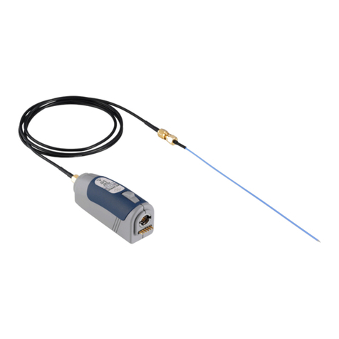
The RF probe is a universal tool for mea-
suring RF voltages. The low input capaci-
tance of 2.5 pF makes it virtually non-
loaded and ideally suitable for measure-
ments on non-coaxial circuits up to
500 MHz or up to 1 GHz when appropriate
accessories are used. A plug-on divider
extends the voltage measurement range
from 10 V to 1000 V and at the same time
reduces the input capacitance to 0.5 pF.
Compared to active, high-impedance
probes, the dynamic range of the
¸URV5-Z7 is greater by a factor of 10
to 100, i.e. higher voltages can be mea-
sured with the same sensitivity. With a
dynamic range from 200 ΠV to 10 V with-
out the use of a plug-on divider, the probe
covers all voltage levels common in state-
of-the-art electronic equipment.
Typical frequency response of the RF Probe ¸URV5-Z7 with voltage mea-
surements on a matched 50
:
line (without adapter, short ground connec-
tion); a) direct, b) with 20 dB plug-on divider, c) with 40 dB plug-on divider
Typical SWR of a matched 50
:
line after connecting the RF Probe
¸URV5-Z7 (without adapter, short ground connection);
a) direct, b) with 20 dB plug-on divider, c) with 40 dB plug-on divider
The RF Probe ¸URV5-Z7, 200 µV to 10 (1000) V, 20 kHz to 1 GHz
RF
Probe
R&S®URV5-Z7
The
RF
probe
is
a
universal
tool
for
mea-
suring
RF
voltages.
The
low
input
capaci-
tance
of
2.5
pF
makes
it
virtually
non-
loaded
and
ideally
suitable
for
measure-
ments
on
non-coaxial
circuits
up
to
500
MHZ
oruptol
GHz
when
appropriate
accessories
are
used.
A
plug-on
divider
extends
the
voltage
measurement
range
from
10
Vto
1000
V
and
at
the
same
time
reduces
the
input
capacitance
to
0.5
pF.
Compared
to
active,
high-impedance
probes,
the
dynamic
range
of
the
R&S®URV5-Z7
is
greater
by
a
factor
of
10
to
100,
Le.
higher
voltages
can
be
mea-
sured
with
the
same
sensitivity.
With
a
dynamic
range
from
200
uV
to
10
V
with-
out the
use
ot
a
plug-on
divider,
the
probe
covers
all
voltage
levels
common
in
state-
of-the-art
electronic
equipment.
The
RFProhe
3&3”
UHV5—Z7,
200/1
Vto
10
(1000/
V,
20
kHz
to
1
GHZ
—>
n.
e
m
U1
4/
//,/
0
,
4//
10
100
200 300
400
MHZ
500
Frequency
4»
./
/
P
r.n
Frequency
response
Typical
frequency
response
of
the
BFProhe
H880
URI/517
with
voltage
mea-
surements
on
a
matched
50
.Qline
(without
adapter,
short
ground
connec-
tion);
a)
direct,
h}
with
20
dB
plug-on
divider,
c)
with
40
dB
plug-on
divider
4
Voltage
Sensors
R&S°’UBV5-Z
/
/°
/
\\
/
///
%/
10
100
200 300
400
MHz
500
Frequency
4»
1
Typical
SW]?
of
a
matched
50
Qline
after
connecting
the
HF
Probe
3&8‘5’
URI/517
{without
adapter,
short
ground
connection);
a)
direct,
h}
with
20
dB
plug-0n
divider,
cl
with
40
dB
plug-on
divider
g
/*
ııı
Voltage Sensors ¸URV5-Z 5
Accessories for RF probe
DC Probe ¸URV5-Z1
The low input capacitance of the DC
Probe ¸URV5-Z1 makes it particularly
suitable for measurements in RF circuits.
Since the probe is virtually non-loaded,
the circuit under test remains largely
unaffected. This prevents the operating
point of active circuits from being shifted,
which can occur with high capacitive
loading.
The DC Probe ¸URV5-Z1, 1 mV to 400 V, 3 pF
÷÷
9 M
:
Accessory Set ¸URV-Z6
20 dB and 40 dB plug-on dividers for extending the voltage measurement range and
reducing the input capacitance to 100 V/1 pF or 1000 V/0.5 pF. BNC adapter for level
measurements in 50 :coaxial lines (see also Insertion Units ¸URV5-Z2/-Z4).
Adapters ¸URV-Z50 and ¸URV-Z3
With integrated termination for power measurements on matched sources, the
adapters make the probe a power sensor with an extremely wide dynamic range of
93 dB. For increasing the measurement accuracy with the 50': adapter connected,
frequency response correction data is stored in each probe.
20/40 dB plug-on dividers and BNC adapter
¸URV-Z50: 50 :, 20 kHz to 1 GHz,
1 nW to 2 W
¸URV-Z3: 75 :, 20 kHz to 500 MHz,
0.5 nW to 1.3 W
Accessories
for
RF
probe
Accessory
Set
R&S®URV-Zö
20
dB
and
40
dB
plug-on
dividers
for
extending
the
voltage
measurement
range
and
reducing
the
input
capacitance
to
100
V/l
pF
or
1000
V/0.5
pF.
BNC
adapter
for
level
measurements
in
50
Q
coaxial
lines
(see
also
Insertion
Units
R&S®URV5-ZZ/—Z4).
Adapters
R&S®URV-250
and
R&S®URV-Z3
With
integrated
termination
for
power
measurements
on
matched
sources,
the
adapters
make
the
probe
a
power
sensor
with
an
extremely
wide
dynamic
range
of
93
dB.
For
increasing
the
measurement
accuracy
with
the
50
Q
adapter
connected,
frequency
response
correction
data
is
stored
in
each
probe.
20
kHz
to
1
6H2,
.
DC
Probe
R&S®URV5-Z1
The
low
input
capacitance
of
the
DC
Probe
R&S®
URV5-Z1
makes
it
particularly
suitable
for
measurements
in
RF
circuits.
Since
the
probe
is
virtually
non-loaded,
the
circuit
under
test
remains
largely
unaffected.
This
prevents
the
operating
point
ofactive
circuits
from
being
shifted,
which
can
occur
with
high
capacitive
loading.
The
at:
Probe
[me
uni/MI,
1
m
V
to
400
V,
3
pr
//9
Mg
Voltage
sensors
nasounvs-z
5
6Voltage Sensors ¸URV5-Z
The built-in detectors offer a dynamic
range of more than 90 dB for spectrally
pure sinusoidal signals with an unmodu-
lated envelope (CW, FM, ΜM, GMSK,
FSK, etc). This yields a voltage measure-
ment range of 200 ΠV to 10 V (#60 dBm
to +33 dBm into 50 :) for the
¸URV5-Z2,andof2mVto100V
(#40 dBm to +53 dBm into 50 :) for the
¸URV5-Z4. With modulated envelope
or high harmonic content, the insertion
units should be operated only within the
square-law region of the detectors, which
for the ¸URV5-Z2 ends at approx.
22 mV
(
#
20 dBm into 50
:
) and for the
¸URV5-Z4
at 220 mV (0 dBm into
50 :). In this region, the behavior of the
insertion units is similar to that of a ther-
mal power meter, i.e. the rms voltage or
the equivalent average power is mea-
sured.
Owing to the high decoupling of the
detector from the RF connectors, inser-
tion loss of the ¸URV5-Z4 is very low,
i.e. not exceeding that of a line of equiva-
lent length. The ¸URV5-Z4 is there-
fore truly transparent and can be inserted
into any test circuit without influencing
the parameters to be measured.
Both insertion units are equipped with a
calibration data memory that contains
information about the individual sensor
characteristics such as frequency
response, linearity, temperature coeffi-
cient, etc. The stored data is automati-
cally considered by the base unit during
operation so that the user can plug the
sensor in and immediately start measur-
ing.
Insertion Units ¸URV5-Z2
and ¸URV5-Z4
The Insertion Units ¸URV5-Z2 and
¸URV5-Z4 are used for uninterrupted
level measurements between source and
load and for terminated power measure-
ments. Due to their wide frequency range
they are ideal especially for the measure-
ment of EMC test levels as well as many
general-purpose applications.
Compared to the terminating power sen-
sors of the ¸NRV family, the
¸URV5-Z2 and ¸URV5-Z4 inser-
tion units offer a larger dynamic range, a
much lower frequency limit (9 kHz with
the ¸URV5-Z2) and the possibility of
using them during operation of the load.
Both units are made up of a short, coaxial
line between the two RF connectors, in
the middle of which the voltage is
tapped: directly with the ¸URV5-Z2,
and via a capacitive 20 dB divider with
the ¸URV5-Z4. If the insertion units
are match-terminated, the voltage is con-
stant over the whole length of the line, so
a fixed relationship is obtained between
applied RF power and test voltage:
P =Vrms2/50:. In this configuration, the
insertion units provide precise absolute
power and level measurements.
The insertion units are calibrated so that
the power incident upon them is indi-
cated. With a poorly matched load, pre-
cise absolute-value measurements are
not possible, but relative measurements
can be performed and system applica-
tions implemented in which subsequent
calibration of the complete test setup
takes place. Switchover between voltage,
level and power indication is made at the
base unit.
The Insertion Unit ¸URV5-Z2, 200
Π
V to
'
10 V, 9 kHz to
'
3 GHz
The Insertion Unit ¸URV5-Z4, 2
'
mV to 100 V, 100 kHz to 3 GHz
Insertion
Units
R&S
®URV5-Z2
and
R&S®URV5—Z4
The
Insertion
Units
R&S®URV5-22
and
R&S®
UFlV5-Z4
are
used
for
uninterru
pted
level
measurements
between
source
and
load
and
for
terminated
power
measure-
ments.
Due
to
theirwide
frequency
range
they
are
ideal
especially
for
the
measure-
ment
of
EMC
test
levels
as
well
as
many
general-purpose
applications.
Compared
to
the
terminating
power
sen-
sors
of
the
R&S®NRV
family,
the
R&S®URV5-ZZ
and
R&S®URV5-Z4
inser-
tion
units
offer
a
larger
dynamic
range,
a
much
lower
frequency
limit
(9
kHz
with
the
R&S®URV5-Z2)
and
the
possibility
of
using
them
during
operation
of
the
load.
Both
units
are
made
up
ofa
short,
coaxial
line
between
the
two
RF
connectors,
in
the
middle
of
which
the
voltage
is
tapped:
directly
with
the
R&S®
URV5-ZZ,
and
via
a
capacitive
20
dB
divider
with
the
R&S®URV5—Z4.
If
the
insertion
units
are
match-terminated,
the
voltage
is
con-
stant
overthe
whole
length
of
the
line,
so
a
fixed
relationship
is
obtained
between
applied
RF
power
and
test
voltage:
P
=V,ms2
/
50
Q.
In
this
configuration,
the
insertion
units
provide
precise
absolute
power
and
level
measurements.
The
insertion
units
are
calibrated
so
that
the
power
incident
upon
them
is
indi-
cated.
With
a
poorly
matched
load,
pre-
cise
absolute-value
measurements
are
not
possible,
but
relative
measurements
can
be
performed
and
system
applica-
tions
implemented
in
which
subsequent
calibration
of
the
complete
test
setup
takes
place.
Switchover
between
voltage,
level
and
power
indication
is
made
at
the
base
unit.
6
Voltage
Sensors
R&ssunvs-z
:Il'i
Ifilli.
IT
HQ.
Ini'flnfl
"H
Illl
II
(im
Imimu
m
‚
The
Insertion
Unit
R&S”
URI/522,
200
‚uV
to
10
V,
0
kHz
to
3
GHz
The
Insertion
Unit
R&S”
UHV5—Z4,
2
ta
100
V,
100
kHz
to
3
GHz
The
built-in
detectors
offer
a
dynamic
range
of
more
than
90
dB
for
spectrally
pure
sinusoidal
signals
with
an
unmodu-
lated
envelope
(CW,
FM,
(pM,
GMSK,
FSK,
etc).
This
yields
a
voltage
measure-
ment
range
of
200
pV
to
10
V
(—60
dBm
to
+33
dBm
into
50
Q)
for
the
R&S®URV5-Z2,
and
of
2
mV
to
100
V
(—40
dBm
to
+53
dBm
into
50
Q)
for
the
0&8®
URV5-Z4.
With
modulated
envelope
or
high
harmonic
content,
the
insertion
units
should
be
operated
only
within
the
square-law
region
ofthe
detectors,
which
for
the
R&S®URV5-Z2
ends
at
approx.
22
mV
(—20
dBm
into
50
Q)
and
for
the
R&S®URV5-Z4
at
220
mV
(0
dBm
into
50
Q).
In
this
region,
the
behavior
of
the
insertion
units
is
similar
to
that
of
a
ther-
mal
power
meter,
i.e.
the
rms
voltage
or
the
equivalent
average
power
is
mea-
sured.
Owing
to
the
high
decoupling
of
the
detector
from
the
RF
connectors,
inser-
tion
loss
ofthe
R08®
URV5-Z4
is
very
low,
i.e.
not
exceeding
that
of
a
line
of
equiva-
lent
length.
The
R&S®URV5-Z4
is
there-
fore
truly
transparent
and
can
be
inserted
into
any
test
circuit
without
influencing
the
parameters
to
be
measured.
Both
insertion
units
are
equipped
with
a
calibration
data
memory
that
contains
information
about
the
individual
sensor
characteristics
such
as
frequency
response,
linearity,
temperature
coeffi-
cient,
etc.
The
stored
data
is
automati-
cally
considered
by
the
base
unit
during
operation
so
that
the
user
can
plug
the
sensor
in
and
immediately
start
measur-
Ing.
Voltage Sensors ¸URV5-Z 7
Power sensors
Power sensors of the ¸NRV-Z series
listed in the table below are available for
further applications. (For more detailed
information, refer to the ¸NRV-Z data
sheet, PD 0758.2248.32.)
¸NRV-Z1
0828.3018.02
Diode Power Sensor 50 :
10 MHz to 18 GHz, 200 pW to 20 mW
Power measurements of highest sensitivity up to 18 GHz in 50 :systems
¸NRV-Z2
0828.3218.02
Diode Power Sensor 50 :
10 MHz to 18 GHz, 20 nW to 500 mW
Power measurements with minimum mismatch, for high powers in 50 :systems
¸NRV-Z3
0828.3418.02
Diode Power Sensor 75 :
1 MHz to 2.5 GHz, 100 pW to 13 mW
Power measurements in 75 :'systems
¸NRV-Z4
0828.3618.02
Diode Power Sensor 50 :
100 kHz to 6 GHz, 100 pW to 20 mW
Power measurements of highest sensitivity in the frequency range 100 kHz to 6 GHz,
very large dynamic range
¸NRV-Z5
0828.3818.02
Diode Power Sensor 50 :
100 kHz to 6 GHz, 10 nW to 500 mW
Same as ¸NRV-Z4, but for high powers and minimum mismatch
¸NRV-Z6
0828.5010.02
Diode Power Sensor 50 :
50 MHz to 26.5 GHz, 400 pW to 20 mW
Power measurements up to 26.5 GHz with high sensitivity and dynamic range in 50 :sys-
tems (PC 3.5 connector)
¸NRV-Z15
1081.2305.02
Diode Power Sensor 50 :
50 MHz to 40 GHz, 400 pW to 20 mW
Power measurements up to 40 GHz with high sensitivity and dynamic range in 50 :systems
(2.92 mm connector)
¸NRV-Z31
0857.9604.02/03/04
Peak Power Sensor 50 :
30 MHz to 6 GHz, 1 ΠW to 20 mW
Peak power measurements, pulse width τ2 (200) Πs, pulse repetition rate τ10 (100) Hz,
3 models
¸NRV-Z32
1031.6807.04/05
Peak Power Sensor 50 :
30 MHz to 6 GHz, 100 ΠW to 2 (4) W
Peak power measurements, pulse width τ2 (200) Πs, pulse repetition rate τ25 (100) Hz,
2 models
¸NRV-Z33
1031.6507.03/04
Peak Power Sensor 50 :
30 MHz to 6 GHz, 1 mW to 20 W
Peak power measurements up to 20 W, pulse width τ2 (200) Πs, pulse repetition rate
τ100 Hz, 2 models
¸NRV-Z51
0857.9004.02
Thermal Power Sensor 50 :
DC to 18 GHz, 1 ΠW to 100 mW
High-precision power measurements also with non-sinusoidal signals
¸NRV-Z52
0857.9204.02
Thermal Power Sensor 50 :
DC to 26.5 GHz, 1 ΠW to 100 mW
Same as ¸NRV-Z51, but with PC 3.5 connector for measurements up to 26.5 GHz
¸NRV-Z53
0858.0500.02
Thermal Power Sensor 50 :
DC to 18 GHz, 100 ΠW to 10 W
High-power measurements up to 10 W also with non-sinusoidal signals
¸NRV-Z54
0858.0800.02
Thermal Power Sensor 50 :
DC to 18 GHz, 300 ΠW to 30 W
High-power measurements up to 30 W also with non-sinusoidal signals
¸NRV-Z55
1081.2005.02
Thermal Power Sensor 50 :
DC to 40 GHz, 1 ΠW to 100 mW
Same as ¸NRV-Z51, but with 2.92 mm connector for measurements up to 40 GHz
Power
sensors
Power
sensors
of
the
R&S®NRV-Z
series
listed
in
the
table
below
are
available
for
further
applications.
(For
more
detailed
information,
refer
to
the
R&S®
NRV-Z
data
sheet,
PD
0758224832.)
R&S®NRV-Z1
Diode
Power
Sensor
50
£2
Power
measurements
of
highest
sensitivity
up
to
18
GHz
in
50
£2
systems
0828.3018.02
10
MHz
to
18
GHz,
200
pW
to
20
mW
VR&S°NBV-ZZ
Diode
Power
Sensor
50
£2
Power
measurements
with
minimum
mismatch,
for
high
powers
in
50
£2
syste
0828321802
10
MHz
to
18
GHz,
20
nW
to
500
mW
L
R&S®NRV-Z3
Diode
Power
Sensor
75
£2
Power
measurements
in
75
£2
systems
0828.341802
1
MHz
to
2.5
GHz,
100
pW
to
13
mW
R&S”NRV-Z4
Diode
Power
Sensor
50
£2
Power
measurements
of
highest
sensitivity
in
the
frequency
range
100
kHz
to
6
G
0828361802
100
kHz
to
6
GHz,
100
pW
to
20
mW
VEW
Iarge
dynamic
range
R&S®NRV-Z5
Diode
Power
Sensor
50
£2
Same
as
R8S®NRV-Z4,
but
for
high
powers
and
minimum
mismatch
0828.381802
100
kHz
to
6
GHz,
10
nW
to
500
mW
R&S”NRV-ZG
Diode
Power
Sensor
50
£2
Power
measurements
up
to
26.5
GHZ
with
high
sensitivity
and
dynamic
range
in
50
0828501002
50
MHz
to
26.5
GHz,
400
pW
to
20
mW
tems
(PC
3.5
connector)
R&S®NRV-Z15
Diode
Power
Sensor
50
£2
Power
measurements
up
to
40
GHz
with
high
sensitivity
and
dynamic
range
in
50
£2
systems
1081.230502
50
MHz
to
40
GHz,
400
pW
to
20
mW
(2.92
mm
connector)
R&S”NRV-Z31
Peak
Power
Sensor
50
£2
Peak
power
measurements,
pulse
width
22
(200)
„s,
pulse
repetition
rate
210
(100)
0857.9604.02/03l04
30
MHz
to
6
GHz,
1
„W
to
20
mW
3
models
R&S®NRV-Z32
Peak
Power
Sensor
50
£2
Peak
power
measurements,
pulse
width
22
(200)
„s,
pulse
repetition
rate
225
(100)
Hz,
1031.6807.04/05
30
MHz
to
6
GHz,
100
„W
to
2
(4)
W
2
models
R&S”NRV-Z33
Peak
Power
Sensor
50
£2
Peak
power
measurements
up
to
20
W,
pulse
width
22
(200)
„s,
pulse
repetition
ra,
1031.6507.03I04
30
MHz
to
6
GHz,
1
mW
to
20
W
2100
Hz,
2
models
*
R&S®NRV-Z51
Thermal
Power
Sensor
50
£2
High-precision
power
measurements
also
with
non-sinusoidal
signals
0857.9004.02
DC
to
18
GHz,
1
„W
to
100
mW
R&S”NRV-Z52
Thermal
Power
Sensor
50
£2
Same
as
R&S®NHV-Z51‚
but
with
PC
3.5
connector
for
measurements
up
to
26.5
((5
0857020402
DC
to
26.5
GHz,
1
„W
to
100
mW
R&S®NRV-Z53
Thermal
Power
Sensor
50
£2
High-power
measurements
up
to
10
W
also
with
non-sinusoidal
signals
0858050002
DC
to
18
GHz,
100
„W
to
10
W
R&S”NRV-Z54
Thermal
Power
Sensor
50
£2
High-power
measurements
up
to
30
W
also
with
non-sinusoidal
signals
‚
0858080002
DC
to
18
GHz,
300
„W
to
30
W
R&S®NRV-Z55
Thermal
Power
Sensor
50
£2
Same
as
R&S®NRV—Z51,
but
with
2.92
mm
connector
for
measurements
up
to
40
GHz
1081.2005.02
DC
to
40
GHz,
1
„W
to
100
mW
Voltage
Sensors
8&S°URV5-Z
7
ı
I .I
8Voltage Sensors ¸URV5-Z
Specifications
Measurement uncertainties
In the temperature range 18°C to 28°C for spectrally pure sinewave signals and DC voltage (DC Probe ¸URV5-Z1 only). Values in dB and in % (in parentheses;
referenced to measured voltage). The effects of base unit, zero offset, display noise and ambient temperature (out of specified range) are to be considered separately.
Type Frequency range
Impedance
Voltage measurement
range
Max. rating
Power /level
measurement
range
SWR (reflection coefficient) max. Ins. loss in
dB (max.)
8)
RF
connector
RF Probe
¸URV5-Z7
20 kHz to 500 MHz5)
2.5 pF÷÷ 80 k:1)
200 ΠV to 10 V
15 V (rms)
22 V (pk), 60 V (DC)15)
1 nW to 2 W
–60/+33 dBm
——BNC
(female/
female)
With 20 dB plug-
on divider
(¸URV-Z6)
1 MHz to 500 MHz5)
1 pF÷÷ 1 M:1) 2 mV to 100 V
150 V (rms)2)
220 V (pk), 1000 V (DC)
100 nW to 20 W4)
–40/+43 dBm
— — BNC
(female/
female)
With 40 dB plug-
on divider
(¸URV-Z6)
0.5MHzto500MHz
5)
0.5 pF÷÷ 10 M:1) 20 mV to 1000 V
1050 V(rms)2)3)
1500 V(pk), 1000 V(DC)
10 ΠW to 20 W4)
–20/+43 dBm
— — BNC
(female/
female)
With 50 :'Adapt-
er ¸URV-Z50
20 kHz to 1 GHz
50 :200 ΠV to 10 V
10 V (rms)
22 V (pk)
1 nW to 2 W
–60/+33 dBm
0.02 MHz to 50 MHz: 1.03 (0.015)
>50 MHz to 100 MHz: 1.06 (0.03)
>100 MHz to 500 MHz: 1.11 (0.05)
>500 MHz to 700 MHz: 1.22 (0.10)
>700 MHz to 1 GHz: 1.44 (0.18)
—BNC
(female or
male)
With 75 :'Adapt-
er ¸URV-Z3
20 kHz to 500 MHz
75 :200 ΠV to 10 V
12 V (rms)
22 V (pk)
500 pW to 1.3 W
–62/+31 dBm
0.02 MHz to 100 MHz: 1.03 (0.015)
>100 MHz to 200 MHz: 1.06 (0.03)
>200 MHz to 500 MHz: 1.22 (0.10)
—BNC (male)
2.5/6
1.6/5.6
DC Probe
¸URV5-Z1
—
3 pF÷÷ 9 M:1 mV to 400 V
400 V (pk)
— — — BNC (male)
10 V Insertion
Unit
¸URV5-Z2
9 kHz to 3 GHz
50 :200 ΠV to 10 V6)
15 V (rms) to 1 GHz
from 1 GHz
to 3 GHz
22 V (pk), 50 V (DC)
1 nW to 2 W6)
–60/+33 dBm6)9 kHz to 200 MHz: 1.04 (0.02)
>200 MHz to 500 MHz: 1.10 (0.048)
>500 MHz to 1 GHz: 1.22 (0.10)
>1 GHz to 1.6 GHz: 1.35 (0.15)
>1.6 GHz to 2 GHz: 1.35 (0.15)
>2 GHz to 2.4 GHz: 1.35 (0.15)
>2.4 GHz to 3 GHz: 1.35 (0.15)
0.07
0.2
0.5
1.0
1.5
2.5
3.5
N
(female/
male)
100 V Insertion
Unit
¸URV5-Z4
100 kHz to 3 GHz
50 :2 mV to 100 V7)
150 V (rms) to 1 GHz
from 1GHz
to 3 GHz
220 V (pk), 600 V (DC)
100 nW to 200 W7)
–40/+53 dBm7)0.1 MHz to 500 MHz: 1.04 (0.02)
>500 MHz to 1.6 GHz: 1.07 (0.035)
>1.6 GHz to 2 GHz: 1.07 (0.035)
>2 GHz to 3 GHz: 1.10 (0.048)
0.05
0.1
0.15
0.15
N
(female/
male)
Type Frequency range Without frequency response correction9)With frequency response correction10)
RF Probe
¸URV5-Z712) 20 kHz to 50 kHz
>50 kHz to 100 kHz
>100 kHz to 200 kHz
>0.2 MHz to 32 MHz
>32 MHz to 100 MHz
>100 MHz to 200 MHz
>200 MHz to 500 MHz
#0.2/+0.911)(#2.3/+10)11)
ρ0.2 (ρ2.3)
ρ0.11 (ρ1.3)
ρ0.07 (ρ0.8)
ρ0.16 (ρ1.8)
ρ0.29 (ρ3.3)
#1/+1.1 (ρ12)
–
–
–
–
–
–
–
With 20 dB plug-on divider
(¸URV-Z6)12) 1 MHz to 2 MHz
>2 MHz to 100 MHz
>100 MHz to 200 MHz
>200 MHz to 500 MHz
#1/+1.911) (#12/+20)11)
#1/+1.1 (ρ12)
#1.2/+1.4 (ρ15)
#1.6/+1.9 (ρ20)
–
–
–
–
With 40 dB plug-on divider
(¸URV-Z6)12)
0.5 MHz to 1 MHz
>1 MHz to 100 MHz
>100 MHz to 200 MHz
>200 MHz to 500 MHz
#0.6/+1.911)(#7/+20)11)
ρ0.6 (ρ7)
#0.8/+0.9 (ρ10)
#1.2/+1.4 (ρ15)
–
–
–
–
With 50 :'Adapter
¸URV-Z5013)
20 kHz to 50 kHz
>50 kHz to 100 kHz
>100 kHz to 200 kHz
>0.2 MHz to 32 MHz
>32 MHz to 100 MHz
>100 MHz to 200 MHz
>200 MHz to 500 MHz
>0.5 GHz to 1 GHz
#0.2/+0.911)(#2.3/+10)11)
ρ0.2 (ρ2.3)
ρ0.16 (ρ1.8)
ρ0.11 (ρ1.3)
ρ0.2 (ρ2.3)
ρ0.38 (ρ4.3)
#0.8/+0.9 (ρ10)
#1.6/+1.9 (ρ20)
#1.6/+1.9 (ρ20)
–
–
–
–
0.2 (2.3)
0.29 (3.3)
0.66 (7.3)
1.0 (12) 200 ΠV to 1 V
1.2 (14) !1 V to 10 V
15V rms,-
fGHzε
----------------------
150V rms,-
fGHz,-ε
--------------------------
Specifications
Frequency
range
Voltage
measurement
Power
Ilevel
EWH
(reflection
coefficient)
max.
hrs.
loss
in
Impedance
range
measurement
dB
(max.)'”
con
Max.
rating
range
RF
Probe
20
kHz
to
500
MHz5I
200
pv
to
10
v
1
nW
to
2
w
— —
BNC
R&S®URV5-Z7
2.5
pF
I
I
80
kQ‘)
15
V
(rms)
—60/+33
dBm
(female/
22
v
(pk),
60
v
(013)15’
female)
ith
20
dB
plug-
1
MHzto
500
MHz5’
2
mV
to
100
v
100
nW
to
20
w‘"
— —
8Nc
n
divider
1
pF
I I
1
Mg"
150
v
(rms)2)
410/+43
dBm
(female
&S°UHV—Z6)
220
v
(pk),
1000
v
(DC)
female)
With
40
dB
plug-
0.5
MHz
to
500
MHz5I
20
mV
to
1000
v
10
„w
to
20
W4)
— —
BNC
on
divider
0.5
pF
I
I
10
M9"
1050V(rms)2)3)
—20/+43
dBm
(female/
(H&S®Uilv-zs)
1500
lk),
1000
V(DC)
female)
ith
50
g
Adapt-
20
kHz
to
1
GHz
200
pv
to
10
v
1
nW
to
2
w
0.02
MHz
to
50
MHz:
1.03
(0.015)
—
8Nc
r
R&S®URV-Z50
50
g
10
v
(rms)
—60/+33
dBm
>50
MHz
to
100
MHz:
1.06
(0.03)
(female
or
22
v
(pk)
>100
MHz
to
500
MHz:
1.11
(0.05)
male)
>500
MHz
to
700
MHz:
1.22
(0.10)
>700
MHz
to
1
GHz:
1.44
(0.18)
With
75QAdapt-
20
kHz
to
500
MHz
200
„v
to
10
v
500
pW
to
1.3
w
0.02
MHz
to
100
MHz:
1.03
(0.015)
—
BNC(male)
er
H83®Uilv23
75
g
12
v
(rms)
—62/+31
dBm
>100
MHz
to
200
MHz:
1.06
(0.03)
2.5/6
22
v
(pk)
>200
MHz
to
500
MHz:
1.22
(0.10)
1.6/5.6
C
Probe
—
1
mV
to
400
V
— — —
BNC
&S°UBV5-Zt
3
pF
I I
9
MQ
400
v
(pk)
10
V
Insertion
9
kHz
to
3
GHz
200
uV
to
10
V6)
1
nW
to
2
W5)
9
kHz
to
200
MHz:
1.041002)
0.07
N
Unit
50
Q
15
v
(rms)
to
1
GHz
—60/+33
d8m5>
>200
MHz
to
500
MHz:
1.10
(0.048)
0.2
(female/
R&S®URV5-ZZ
m
from
1
GHz
>500
MHz
to
1
GHz:
12210.10)
0.5
male)
f/GHz
t03GHZ
>1
GHz
to
1.6
GHz:
1.35
(0.15)
1.0
22V(pk)‚
50VIDC)
>1.ß
GHZtoZGHZ:
1.35
(0.15)
1.5
>2
GHz
to
2.4
GHz:
1.35
(0.15)
2.5
>2.4
GHz
to
3
GHz:
1.35
(0.15)
3.5
0
v
Insertion
100
kHz
to
3
GHz
2
mV
to
100
v7)
100
nW
to
200
W7)
0.1
MHz
to
500
MHz:
1.04
(0.02)
0.05
N
nit
509
150
V
(rms)
to
1
GHz
—40/+53
dBm7)
>500
MHz
to
1.6
GHZ:
1.07
(0.035)
0.1
(female/
gsounv5_z4
150V(rmS)
from
1GHz
>1.6
GHz
to
2
GHz:
1.07
(0.035)
0.15
male)
/—f/(G„Z)
m
3
GHz
>2
GHz
to
3
GHz:
1.10
(0.048)
0.15
h
220
v
(pk),
600
v
(DC)
Measurement
uncertainties
In
the
temperature
range
18°C
to
28°C
for
spectrally
pure
sinewave
signals
and
DC
voltage
(DC
Probe
R&S®URV5-Z1
only).
Values
in
dB
and
in
%
(in
parentheses;
referenced
to
measured
voltage).
The
effects
of
base
unit,
zero
offset,
display
noise
and
ambient
temperature
(out
of
specified
range)
are
to
be
considered separately.
-
f
Frequency
range
"mmt
frequency
response
cum!"
RF
Probe
20
kHz
to
50
kHz
—0.2/+0.9“)
(—2.3/+10)">
—
R&S®URV5-Z712’
>50
kHz
to
100
kHz
$0.2
($2.3)
—
>100
kHz
to
200
kHz
$0.11
($1.3)
—
>0.2
MHz
to
32
MHz
$0.07
($0.8)
—
>32
MHz
to
100
MHz
$0.16
($1.8)
—
>100
MHz
to
200
MHz
$0.29
($3.3)
—
>200
MHz
to
500
MHz
—1/+1.1
($12)
—
20
dB
plug-on
divider
1
MHz
t0
2
MHz
—1/+1
.31”
(—12/+20)”)
—
seunv-ze)
I
>2
MHz
to
100
MHz
—1/+1
.1
($12)
—
>100
MHz
to
200
MHz
—1.2/+1.4
($15)
—
>200
MHz
to
500
MHz
—1.6/+1.9
($20)
—
With
40
dB
plug-on
divider
0.5
MHz
to
1
MHz
—0.6/+1.9“)
(—7/+20)”>
—
(H&S®URV-ZB)12)
>1
MHz
to
100MHz
$0.6
($7)
—
>100
MHz
to
200
MHz
—0.8/+0.9
($10)
—
>200
MHz
to
500
MHz
—1.2/+1.4
($15)
—
ith
50
g
Adapter
20
kHz
to
50
kHz
—0.2/+0.9”>
(—2.3/+101"’
—
seunvzsowl
>50
kHz
to
100
kHz
$0.2
($2.3)
—
>100
kHz
to
200
kHz
$0.16
($1.8)
—
>02
MHz
to
32
MHz
$0.11
($1.3)
—
>32
MHz
to
100
MHz
$0.2
($2.3)
0.2
(2.3)
>100
MHz
to
200
MHz
$0.38
($4.3)
029
(33)
>200
MHZ
to
500
MHZ
—0.8/+Ü.9
(iIÜ)
0.56
(73)
>05
GHZ
t0
1
GHZ
—1.6/+1.9
($20)
1.0
(12)
200
”V
to
1
V
‘1-5/“3
(ml
1.2(14)>1Vto10V
8
Voltage
Sensors
R&S°UHV5-Z
-I-_
--
-I
-__-_--
IIIIIIIIII
-_
--
_-
--
_
____-
J
ııııııııııı
Voltage Sensors ¸URV5-Z 9
Measurement uncertainties
Values in dB and in % (in parentheses; referenced to measured voltage)
With 75 :'Adapter
¸URV-Z313)
20 kHz to 50 kHz
>50 kHz to 100 kHz
>100 kHz to 200 kHz
>0.2 MHz to 32 MHz
>32 MHz to 100 MHz
>100 MHz to 200 MHz
>200 MHz to 500 MHz
#0.2/+0.911) (#2.3/+10)11)
ρ0.2 (ρ2.3)
ρ0.16 (ρ1.8)
ρ0.11 (ρ1.3)
ρ0.2 (ρ2.3)
ρ0.38 (ρ4.3)
#1/+1.1 (ρ12)
–
–
–
–
–
–
–
Type Frequency range With frequency response correction10)
up to1 V (20 mW/+13 dBm)
With frequency response correction10)
above 1 V (20 mW/+13 dBm)
10 V Insertion Unit
¸URV5-Z214)
at ¸URV35,
¸URV55,
¸NRVS, ¸NRVD
9 kHz to 20 kHz
!20 kHz to'50 kHz
!50 kHz to 100 kHz
!100 kHz to 100 MHz
!100 MHz to 200 MHz
!200 MHz to 500 MHz
!0.5 GHz to 1.0 GHz
!1.0 GHz to 1.6 GHz
!1.6 GHz to 2.0 GHz
!2.0 GHz to 2.4 GHz
!2.4 GHz to 3.0 GHz
0.3511) (4.0)11)
0.2011) (2.3)11)
0.17 (2.0)
0.13 (1.5)
0.17 (2.0)
0.20 (2.3)
0.25 (2.9)
0.30 (3.5)
0.35 (4.0)
0.40 (4.6)
0.50 (5.8)
0.2011) (2.3)11)
0.1711) (2.0)11)
0.17 (2.0)
0.13 (1.5)
0.17 (2.0)
0.25 (2.9)
0.30 (3.5)
0.40 (4.6)
0.50 (5.8)
0.60 (6.9)
0.75 (8.6)
10 V Insertion Unit
¸URV5-Z214)
at ¸URV5, ¸NRV
!9 kHz to 20 kHz
!20 kHz to 50 kHz
!50 kHz to 100 kHz
!100 kHz to 100 MHz
!100 MHz to 200 MHz
!200 MHz to 500 MHz
!0.5 GHz to 1.0 GHz
!1.0 GHz to 1.6 GHz
!1.6 GHz to 2.0 GHz
!2.0 GHz to 2.4 GHz
!2.4 GHz to 3.0 GHz
0.4511) (5.2)11)
0.2011) (2.3)11)
0.17 (2.0)
0.13 (1.5)
0.20 (2.3)
0.25 (2.9)
0.35 (4.0)
0.45 (5.2)
0.55 (6.3)
0.65 (7.5)
0.85 (9.8)
0.3011) (3.5)11)
0.2011) (2.3)11)
0.17 (2.0)
0.13 (1.5)
0.20 (2.3)
0.30 (3.5)
0.40 (4.6)
0.55 (6.3)
0.65 (7.5)
0.80 (9.2)
1.05 (12)
Up to 10 V (2 W/+33 dBm) Above 10 V (2 W/+33 dBm)
100 V Insertion Unit
¸URV5-Z414)
at ¸URV35,
¸URV55, ¸NRVS,
¸NRVD
100 kHz to 200 kHz
!200 kHz to 500 kHz
!500 kHz to 1 MHz
!1 MHz to 3 MHz
!3 MHz to 200 MHz
!200 MHz to 500 MHz
!0.5 GHz to 1 GHz
!1.0 GHz to 1.6 GHz
!1.6 GHz to 2.0 GHz
!2.0 GHz to 2.4 GHz
!2.4 GHz to 3.0 GHz
1.5011) (18)11)
0.6011) (6.9)11)
0.2011) (2.3)11)
0.17 (2.0)
0.13 (1.5)
0.17 (2.0)
0.20 (2.3)
0.30 (3.5)
0.35 (4.0)
0.45 (5.2)
0.65 (7.5)
0.5011) (5.8)11)
0.2511) (2.9)11)
0.1711) (2.0)11)
0.13 (1.5)
0.13 (1.5)
0.20 (2.3)
0.25 (2.9)
0.40 (4.6)
0.50 (5.8)
0.70 (8.1)
1.05 (12)
100 V Insertion Unit
¸URV5-Z414)
at ¸URV5, ¸NRV
100 kHz to 200 kHz
!200 kHz to 500 kHz
!500 kHz to 1 MHz
!1 MHz to 3 MHz
!3 MHz to 200 MHz
!200 MHz to 500 MHz
!0.5 GHz to 1.0 GHz
!1.0 GHz to 1.6 GHz
!1.6 GHz to 2.0 GHz
!2.0 GHz to 2.4 GHz
!2.4 GHz to 3.0 GHz
2.2011) (26) 11)
0.8011) (9.2)11)
0.2511) (2.9)11)
0.17 (2.0)
0.13 (1.5)
0.17 (2.0)
0.25 (2.9)
0.45 (5.2)
0.60 (6.9)
0.80 (9.2)
1.15 (14)
0.8011) (9.2)11)
0.4011) (4.6)11)
0.2011) (2.3)11)
0.13 (1.5)
0.13 (1.5)
0.20 (2.3)
0.30 (3.5)
0.55 (6.3)
0.70 (8.1)
1.00 (12)
1.50 (18)
Type Voltage measurement range Measurement uncertainty9)
DC Probe
¸URV5-Z1
1 mV to 100 V
!100 V to 400 V
ρ0.013 (ρ0.15)
ρ0.030 (ρ0.35)
Type Frequency range Without frequency response correction9)With frequency response correction10)
With
75
Q
Adapter
H&S®URV-Z313’
20
kHz
to
50
kHZ
>50
kHZ
to
100
kHZ
>100
kHZ
to
200
kHZ
>0.2
MHZ
to
32
MHZ
>32
MHZ
to
100
MHZ
>100
MHZ
to
200
MHZ
>200
MHZ
to
500
MHZ
Measurement
uncertainties
—0.2/+0.9“’
$0.2
$0.16
$0.11
$0.2
$0.38
—1/+1
.1
Values
in
dB
and
in
%
(in
parentheses;
referenced
to
measured
voltage)
F
Frequency
Eur
‚Wim
frequency
responwmuency
responsew
10
V
Insertion
Unit
9
kHZ
to
20
kHZ
R83®URV5—zz")
>20
kHZ
to
50
kHZ
at
R&S®URV35‚
>50
kHZ
to
100
kHZ
R8130URV55
>100
kHZ
t0
100
MHZ
e
'
0
>100
MHZto
200
MHZ
Res
nnvs,
R&S
nnvn
>200
MHZ
to
500
MHZ
>0.5
GHZto
1.0
GHZ
>1.0
GHZ
to
1.6
GHZ
>1.6
GHZ
to
2.0
GHZ
>2.0
GHZ
to
2.4
GHZ
>2.4
GHZ
to
3.0
GHZ
0
V
Insertion
Unit
>9
kHZ
to
20
kHZ
nasounvs—zz‘“
>20
kHz
to
50
kHZ
at
R&S®URV5‚
R&S°NRV
>50
kHZ
to
100
kHZ
>100
kHZ
to
100
MHZ
>100
MHZ
to
200
MHZ
>200
MHZ
to
500
MHZ
>0.5
GHZ
to
1.0
GHZ
>1.0
GHZ
to
1.6
GHZ
>1.6
GHZ
to
2.0
GHZ
>2.0
GHZ
to
2.4
GHZ
>2.4
GHZ
to
3.0
GHZ
100
V
Insertion
Unit
100
kHZ
to
200
kHZ
nxswunvs—z4")
>200
kHZ
to
500
kHz
at
R&S®URV35‚
>500
kHZ
to
1
MHZ
R&S"URV55,
nxsonnvs.
>1
MHZ
T0
3
MHZ
R&S®NRVD
>3
MHZ
to
200
MHZ
>200
MHZ
to
500
MHZ
>0.5
GHZ
to
1
GHZ
>1.0
GHZ
to
1.6
GHZ
>1.6
GHZ
to
2.0
GHZ
1
>20
GHZ
to
2.4
GHZ
I
>2.4
GHZ
to
3.0
GHZ
100
V
Insertion
Unit
100
kHZ
to
200
kHZ
R&S"URV5-Z4”’
>200
kHZ
to
500
kHz
at
Raswnvs,
nxsonnv
>500
kHz
t0
1
MHZ
>1
MHZ
to
3
MHZ
>3
MHZ
to
200
MHZ
>200
MHZ
to
500
MHZ
>0.5
GHZto1.0
GHZ
>1.0
GHZ
to
1.6
GHZ
>1.6
GHZ
to
2.0
GHZ
>2.0
GHZ
to
2.4
GHZ
>2.4
GHZ
to
3.0
GHZ
(—2.3/+10)‘”
($2.3)
($1.8)
($1.3)
($2.3)
($4.3)
($12)
up
to1
V
(20
l+13
dBm)
0.351”
(4.0)“’
0.20“)
(2.3)“’
0.17
(2.0)
0.13
(1.5)
0.17
(2.0)
0.20
(2.3)
0.25
(2.9)
0.30
(3.5)
0.35
(4.0)
0.40
(4.6)
0.50
(5.8)
_
11)
(52)”)
0.201”
(2.3)‘”
0.17
(2.0)
0.13
(1.5)
0.20
(2.3)
0.25
(2.9)
0.35
(4.0)
0.45
(5.2)
0.55
(6.3)
0.65
(7.5)
0.85
(9.8)
Up
to
10
v
(2
w7+33
dBm)
1.50“)
(18)“)
0.60")
(5.9)"’
0.20“)
(2.3)"’
0.17
(2.0)
0.13
(1
.5)
0.17
(2.0)
0.20
(2.3)
0.30
(3.5)
0.35
(4.0)
0.45
(5.2)
0.65
(7.5)
220‘”
(26)
1”
_
11)
19-21“)
0.25“)
(2.9)“’
0.17
(2.0)
0.13
(1.5)
0.17
(2.0)
0.25
(2.9)
0.45
(5.2)
0.60
(6.9)
0.80
(9.2)
1.15
(14)
above
1
V
(l
l+13
dBm)
0.201”
(2.3)“)
0.17”)
(2.0)“)
0.17
(2.0)
0.13
(1.5)
0.17
(2.0)
0.25
(2.9)
0.30
(3.5)
0.40
(4.6)
0.50
(5.8)
0.60
(6.9)
0.75
(8.6)
_
11)
(35)")
0.20”)
(2.3)“)
0.17
(2.0)
0.13
(1.5)
0.20
(2.3)
0.30
(3.5)
0.40
(4.6)
0.55
(6.3)
0.65
(7.5)
0.80
(9.2)
1.05
(12)
Above
10
v
(2
w7+33
dBm)
.50“)
(5.8)“)
0.25“)
(2.9)“)
0.17“)
(2.0)“)
0.13
(1.5)
0.13
(1.5)
0.20
(2.3)
0.25
(2.9)
0.40
(4.6)
0.50
(5.8)
0.70
(8.1)
1.05
(12)
0.801”
(9.2)“)
0.40“)
(4.6)“)
020“)
(2.3)”)
0.13
(1.5)
0.13
(1.5)
0.20
(2.3)
0.30
(3.5)
0.55
(6.3)
0.70
(8.1)
1.00
(12)
1.50
(18)
DC
Probe
1
mV
to
100
V
R&S°UHV5-Z1
>100
V
to
400
V
i0.013
(i015)
i0.030
(i035)
Voltage
sensors
R&S°URV5—Z
9
|
ıı
«
10 Voltage Sensors ¸URV5-Z
1) Applies to 10 MHz. For impedance at higher frequencies see SWR diagram on page 4.
2) Not with BNC adapter.
3) Up to 40 MHz.
applies at higher frequencies.
4) With BNC adapter (50 :). Maximum power limited by losses in the adapter.
5) Upper limit frequency depending on adapter and source impedance.
6) Up to 1.5 GHz. At higher frequencies the upper limit of the measurement range is to be reduced according to max.rating.
7) Up to 2 GHz. At higher frequencies the upper limit of the measurement range is to be reduced according to max.rating.
8) The insertion loss of the Insertion Unit ¸URV5-Z2 is level-dependent above 0.5 GHz. The specified values refer to low test voltages at which the highest loss is obtained.
9) Measurement uncertainty limits without consideration of correction values for the frequency-dependent response of RF probes. Measurement uncertainty limits are identical with error limits, but with
opposite sign.
10) Expanded uncertainty with a coverage factor k = 2, with the frequency-dependent correction values stored in the probe being taken into account. An expanded uncertainty with k=2 corresponds to a
coverage probability of approx. 95% for a normal distribution of combined errors.
11) In this frequency range the measurement accuracy is strongly voltage- and temperature-dependent. Therefore, at temperatures above 28°C an increase in the measurement uncertainty is to be expected
that is far above the value specified for the temperature effect. In the worst case it can be assumed that the measurement uncertainty will double with every temperature increase of 5 K, i.e. at 33°C, 38°C
etc, for the ¸URV5-Z7 without plug-on divider between 20 kHz and 30 kHz, for the ¸URV5-Z2 between 9 kHz and 15 kHz and for the ¸URV5-Z4 between 100 kHz and 300 kHz.
12) In BNC adapter terminated with 50 :'load. Specifications referenced to incident wave at source terminal. With mismatched load, measurement uncertainty limits may rise due to standing waves by about
±4 dB (SWR-1). The approximation refers to SWR of up to 1.25; for SWR = 1.2 the increase would be ±0.8 dB.
13) Specifications referenced to incident wave.
14) With reflection-free load at the female connector, frequency correction switched on, specifications referenced to incident wave at male connector. Due to standing waves, mismatch of the load can lead to
an additional measurement uncertainty that can be approximated by 2.8 dB x (SWR-1) for the standard uncertainty (formula valid for SWR of up to 1.25).
15) Limited to the specified value for reasons of conformity with international safety standards. Deviating specifications on the type plates of older sensors are to be regarded as the maximum possible physical
rating.
Vrms,-
210V
f
GHz
-----------
♥≠
♣•
------------------------
δ
25:
252'551:
E
3.5.
3‘
Applies
to
10
MHz.
For
impedance
at
higher
frequencies
see
SWR
diagram
on
page
4.
Not
with
BNC
adapter.
Up
to
40
MHz.
<
fl
(”TIS)
T
f
.
. .
(W2)
appliesathigherfrequencres.
With
BNC
adapter(50
(2).
Maximum
power
limited
by
losses
in
the
adapter.
Upper
limit
frequency
depending
on
adapterand
source
impedance.
Up
to
1.5
GHz.
At
higher
frequencies
the
upper
limit
of
the
measurement
range
is
to
be
reduced
according
to
max.rating.
Up
to
2
GHz.
At
higherfrequencies
the
upper
limit
of
the
measurement
range
is
to
be
reduced
according
to
maxrating.
The
insertion
loss
of
the
Insertion
Unit
B8.S®UFlV5-Z2
is
level—dependent
above
0.5
GHz.
The
specified
values
refer
to
low
test
voltages
at
which
the
highest
loss
is
obtained
Measurement
uncertainty
limits
without
consideration
of
correction
values
forthe
frequency-dependent
response
of
BF
probes.
Measurement
uncertainty
limits
are
identical
with
error
limits,
but
with
opposite
sign.
Expanded
uncertainty
with
a
coverage
factor
k
=
2,
with
the
frequency-dependent
correction
values
stored
in
the
probe
being
taken
into
account.
An
expanded
uncertainty
with
k=2
corresponds
to
a
coverage
probability
of
approx. 95%
fura
normal
distribution
of
combined
errors.
In
this
frequency
range
the
measurement
accuracy
is
strongly
voltage-
and
temperature—dependent.
Therefore,
at
temperatures
above
28°C
an
increase
in
the
measurement
uncertainty
is
to
be
expected
that
is
far
above
the
value
specified
for
the
temperature
effect.
In
the
worst
case
it
can
be
assumed
that
the
measurement
uncertainty
will
double
with
every
temperature
increase
of5
K,
Le.
at
33°C,
38
°C
etc,
for
the
H&S®URV5-Z7
without
plug-on
divider
between
20
kHz
and
30
kHz,
for
the
B&S®UBV5-Z2
between
9
kHz
and
15
kHz
and
furthe
R&S@UHV5-Z4
between
100
kHzand
300
kHz.
In
BNC
adapter
terminated
with
50
Q
load.
Specifications
referenced
to
incident
wave
at
source
terminal.
With
mismatched
load,
measurement
uncertainty
limits
may
rise
due
to
standing
waves
by
about
i4
dB
(SWR—1).
The
approximation
refers
to
SWFl
of
up
to
1.25;
for
SWFl
=
1.2
the
increase
would
be
$0.8
dB.
Specifications
referenced
to
incident
wave.
With
reflection-free
load
at
the
female
connector,
frequency
correction
switched
on,
specifications
referenced
to
incident
wave
at
male
connector.
Due
to
standing
waves,
mismatch
of
the
load
can
lead
to
an
additional
measurement
uncertainty
that
can
be
approximated
by
2.8
dB
x
(SWR-1
)
for
the
standard
uncertainty
(formula
valid
for
SWH
of
up
to
125).
Limited
to
the
specified
value
for
reasons
of
conformity
with
international
safety
standards.
Deviating
specifications
on
the
type
plates
of
older
sensors
are
to
be
regarded
as
the
maximum
possible
physical
rating.
Voltage
Sensors
R&S°’UBV5-Z
F
Voltage Sensors ¸URV5-Z 11
Zero offset and display noise (relevant with small voltages/powers only)
DC probe: zero offset ρ0.5 mV, display noise negligible. All other probes: see diagram. For display noise of the Level Meter ¸URV35 see relevant specifications.
Temperature effect1) RF Probe ¸URV5-Z7
without/with accessories
Insertion Units
¸URV5-Z2/-Z4
DC Probe
¸URV5-Z1
18θC to 28θCincluded in measurement uncertainty
10θC to 40θC0.17 dB (2 %) 0.17 dB (2 %) 0.02 dB (0.25 %)
0θC to 50θC0.44 dB (5 %) 0.44 dB (5 %) 0.04 dB (0.5 %)
1) Residual uncertainty (approx. two standard deviations) after internal temperature correction taking into account the temperature characteristic of the sensor and its temperature. The specified temperature
effect does not apply to the frequency ranges specified in footnote 11 (page 10).
Black curve:
Zero offset (within 1 h after
zero adjustment; temperature
variation <1θC; meter with
probe run in for about 2 hours)
Blue curves:
Display noise (2 standard devia-
tions, monitoring time 1 min,
probe temperature 18°C#to
28θC, values about double at
0θC)
Filter designations:
0 to 11 for the ¸URV55,
¸NRVS and ¸NRVD,
F0 to#F5 for the ¸URV5 and
¸NRV
Measured value
Zero offset (±)
Noise (2σ)
1 dB
11%
0.1 dB
1.1%
0.01 dB
0.11%
0.001 dB
0.01%
0/F5
3/F4
5/F311/F0 9/F1 7/F2
All level and power values refer to 50 :. Values for 75 :differ slightly.
RF probe without plug-on divider 200 ΠV 500 ΠV 1 mV 2 mV 5 mV 10 mV
RF probe in 50 :/75 :#adapter &60 dBm &53 dBm &47 dBm &40 dBm &33 dBm
&
27 dBm
10 V Insertion Unit ¸URV5-Z2 1 nW 5 nW 20 nW 100 nW 500 nW 2 ΠW
RF probe with 20 dB plug-on divider 2 mV 5 mV 10 mV 20 mV 50 mV 100 mV
100 V Insertion Unit ¸URV5-Z4 &40 dBm &33 dBm &27 dBm &20 dBm &13 dBm &7 dBm
100 nW 500 nW 2 ΠW 10 ΠW 50 ΠW 200 ΠW
RF probe with 40 dB plug-on divider 20 mV 50 mV 100 mV 200 mV 500 mV 1 V
&20 dBm &13 dBm &7 dBm 0 dBm +7 dBm
+13 dBm
10 ΠW 50 ΠW 200 ΠW 1 mW 5 mW 20 mW
Zero
offset
and
display
noise
(relevant
with
small
voltages/powers
only)
DC
probe:
zero
offset
i0.5
mV,
display
noise
negligible.
All
other
probes:
see
diagram.
For
display
noise
of
the
Level
Meter
R&S®URV35
see
relevant
specifications.
Zero
offset
(1r)
ero
offset
(within
1
h
after
Noise
(20-)
zero
adjustment;
temperature
variation
<1
°C;
meterwith
1
dB
probe
run
in
for
about
2
hours)
11%
Blue
curves:
Display
noise
(2
standard
devia-
tions,
monitoring
time
1
min,
probe
temperature
18°C
to
28°C,
values
about
double
at
0°C)
Filter
designations:
0
to
11
for
the
R&S®URV55‚
R8rS®NRVS
and
R&S®NRVD,
F0
to
F5
forthe
H&S®UHV5
and
R8rS®NRV
3/|:4
0.001
dB
0.01%
11/F0
9/F1
7
F2
5/F3
Measured
value
—>
HF
probe
without
plug-on
divider
200
„V
5
mV
10
mV
RF
probe
in
50
9/75
9
adapter
—60
dBm
—33
dBm
—27
dBm
10
V
Insertion
Unit
R&S®UHV5-22
1
nW
500
nW
2
„W
HF
probe
with
20
dB
plug»on
divider
2
mV
50
mV
100
mV
100
V
Insertion
Unit
H&S®UHV5-Z4
—40
dBm
—13
dBm
—7
dBm
100
nW
50
„W
200
„W
HF
probe
with
40
dB
plug—on
divider
20
mV
500
mV
1
V
—20
dBm
+7
dBm
10
„W
5
mW
eI
and
power
values
refer
to
50
9.
Values
for
75
Q
differ
slightly.
re
one.
or
Probe
naseunvs-zp
Insertion
Units
,
oc
Probe
without/with
accessories
3&8“
UBV5-ZZI-Z4
R&S°URV5-Z1
18°C
to
28°C
included
in
measurement
uncertainty
40°C
0.17
dB
(2
%)
0.17
dB
(2
%)
0.02
dB
(0.25
%)
j
0°C
to
50°C
0.44
dB
(5%)
0.44
dB
(5%)
0.04
dB
(0.5%)
11
Residual
uncertainty
(approx.
two
standard
deviations)
after
internal
temperature
correction
taking
into
account
the
temperature
characteristic
ofthe
sensor
and
its
temperature.
The
specified
temperature
effect
does
not
apply
to
the
frequency
ranges
specified
in
footnote
11
(page
10).
Voltage
Sensors
R&S°URV5—Z
1
1
`. `. \
ı
ıı. ıı. ıı. L L
1
\ ı.
`
1 1 1
L
\
L L. L. L L.
1 1 1 1 1
x
l
I
www.rohde-schwarz.com
Europe: Tel. +49 1805 12 4242, e-mail: customersupport@rohde-schwarz.com · North America: Tel. 888 837 87 72, option 2 (from within the USA and Canada),
+1 410-910-7800, option 2 (from other countries), e-mail: customer.support@rsa.rohde-schwarz.com · Asia: Tel. +65 68463710, e-mail: customersupport.asi[email protected]
¸is a registered trademark of Rohde&Schwarz GmbH&Co. KG · Trade names are trademarks of the owners · Printed in Germany (Pe bb)
PD 5213.5374.32 · ¸URV5-Z· Version 05.00 · May 2005 · Data without tolerance limits is not binding · Subject to change
Specifications
Temperature range meets EN 60068
Operating temperature range 0θC to +50 θC
Storage temperature range –40 θC to +70 θC
Permissible humidity max. 80%, without condensation
Vibration, sinusoidal 5 Hz to 55 Hz, max. 2 g; 55 Hz to 150 Hz,
0.5 g const. (meets EN 60068, EN 61010
and MIL-T-28800 D, class 5)
Vibration, random 10 Hz to 500 Hz, acceleration 1.9 g rms
(meets EN 60068)
Shock 40 g shock spectrum
(meets MIL-STD-810 D, EN 60068)
EMC meets EN 50081-1 and 50082-1,
EMC directive of EC (89/336/EEC), EMC
law of the Federal Republic of Germany
and MIL-STD-461 C (RE 02, CE 03,
RS 03, CS 02)
Safety meets EN 61010
Length of connecting cable approx. 1.2 m for ¸URV5-Z1 and
¸URV5-Z7, 1.3 m or 5 m for
¸URV5-Z2 and ¸URV5-Z4
(depending on model), other lengths
on request
Ordering information
Designation Type Order No.
RF Probe with case,
ground cable, ground
sleeve and strip, hook
and solder tip
¸URV5-Z7 0395.2615.02
DC Probe with ground
cable, clip-on tip and
BNC adapter
¸URV5-Z1 0395.0512.02
10 V Insertion Unit 50 :,
3 GHz with 1.3 m cable
¸URV5-Z2 0395.1019.02
10 V Insertion Unit 50 :,
3 GHz with 5 m cable
¸URV5-Z2 0395.1019.05
100 V Insertion Unit 50
:
,
3 GHz with 1.3 m cable
¸URV5-Z4 0395.1619.02
100 V Insertion Unit 50
:
,
3 GHz with 5 m cable
¸URV5-Z4 0395.1619.05
Recommended extras
For RF probe
Accessory Set including
20/40 dB plug-on divid-
ers, 50 :BNC adapter
with sleeve for plug-on
divider, ground sleeve
and strip
¸URV-Z6 0292.5364.02
50 :Adapter (BNC
female) with adapter to
BNC male
¸URV-Z50 0394.9816.50
75 :Adapter with
adapters to BNC male,
2.5/6 and 1.6/5.6 connec-
tor
¸URV-Z3 0243.9118.70
For Insertion Units ¸URV5-Z2, ¸URV5-Z4
Precision Termination
1 W, 50 :, 0 GHz to'
18 GHz (SWR 51.02 to
1GHz)
¸RNA 0272.4510.50
Termination 1 W, 50 :6
0GHzto'4GHz,
(SWR <1.05 to 1 GHz)
¸RNB 0272.4910.50
Certified Quality System
ISO 9001
DQS REG. NO 1954 QM
Certified Environmental System
ISO14001
DQS REG. NO 1954 UM
More information at
www.rohde-schwarz.com
(search term: URV5-Z)
Specifications
Ordering
information
Operating
temperature
range
0
°C
to
+50
°C
HF
Probe
with
case,
R&S®UHV5-Z7
0395261502
v
round
cable,
round
’
Storage
temperature
range
—40
°C
to
+70
°C
Sleeve
and
strif),
hook
Permissible
humidity
max.
80%,
without
condensation
80d
solder
tip
ibration,
sinusoidal
5
Hz
to
55
Hz,
max.
2
g;
55
Hz
to
150
Hz,
DC
Probe
With
ground
R&S®UHV5-Z1
0395051202
0.5
9
const.
(meets
EN
60068,
EN
61010
cable,
cl—on
tlp
and
and
MlL—T—28800
D,
class
5)
BNC
adapter
\
Vibration,
random
10
Hz
to
500
Hz,
acceleration
1.9
g
rms
10
V
Insertion
Unit
50
9.
R&S®URV5-ZZ
0395101902
(meets
EN
60068)
3
GHZ
with
1.3
m
cable
40
g
shock
spectrum
10
V
Insertion
Unit
5U
Q,
R&S®UHV5-ZZ
0395101905
(meets
MIL-STD-810
D,
EN
60068)
3
GHZ
With
5
m
cable
EMC
meets
EN
50031.1
and
50032.1,
100V
Insertion
Unit
50
Q,
R&S®URV5-Z4
0395161902
EMC
directive
of
EC
(89/336/EEC),
EMC
3
GHZ
With
1.3
m
cable
law
of
the
Federal
Republic
of
Germany
-
-
0
_
and
MIL-STD-461
0
(RE
02'
CE
03'
äonz
13:36.52);
0012:)
1530
g,
R&S
UHV5
Z4
0395161905
1'
RS
03,
CS
02)
1
-
I
III
meets
EN
61010
I
Recommended
extras
/
Length
of
connecting
cable
approx.
1.2
m
for
R&S®URV5-Z1
and
For
HF
probe
‘
R&S®UHV5-Z7‚
1.3
m
or
5
m
f0!
Accessory
Set
including
R&S®UHV—Z6
0292536402
R&S®URV5-ZZ
and
H&S®URV5-Z4
20/40
dB
plug-on
divid-
(depending
on
model),
other
lengths
ers,
50
Q
BNC
adapter
on
request
with
sleeve
for
plug-on
divider,
ground
sleeve
and
strip
50
Q
Adapter
(BNC
R&S®UHV-Z50
0394981650
female)
with
adapter
to
BNC
male
75
Q
Adapter
with
R8S®
URV-Z3
0243911870
Certified
Quality
System
Certified
Environmental
System
adapters
to
BNC
male,
'30
90
o1
ISO
14001
2.5/6
and
1.6/5.6
connec-
tor
)For
Insertion
Units
B&S°URV5—ZZ,
B&S°UHV5-Z4
Precision
Termination
R&S®HNA
0272.4510.50
1
W,
50
Q,
0
GHzto
18
GHZ
(SWR
<1.02
to
1
GHZ)
wwwgggoggfiägpzactom
Iermination
1
w,
50
g,
R&S®HNB
0272.491050
i
H&S®is a
registered
trademark
of
Rohde&Schwarz
GmbH&Co.
KG -
Trade
names
are
trademarks
ofthe
owners -
Printed
in
Germany
(Pe
bb)
PD
5213537432 -
H8S®URV5-Z-
Version
05.00 -
May
2005 -
Data
without
tolerance
limits
is
not
binding -
Subject
to
change
H
t
46H
(search
term:
UHV5-Z)
22105131
GHz)
ROHDE&SCHWARZ
www.r0hde-schwarz.c0m
Europe:
Tel.
+49
1805
12
4242,
e-mail:
[email protected]
-
North
America:
Tel.
888 837
87
72,
option
2
(from
within
the
USA
and
Canada),
+1
410-910—7800,
option
2
(from
other
countries),
e-mail:
[email protected]
-
Asia:
Tel.
+65
68463710,
e-mail:
[email protected]
IIIIIIIIIIIIII
ıııııııııııııı
II
ıı
ıııııııııııııııı
IIIIIIIIIIIIIIII
'
I
I
IIIIIIIIIIII
I
II I
Il
ROHDE&SCHWARZ
2
Note:
on
garation
DC
Probe
URVS-z1,
RF
Probe
URVS-z7.
10-V
'Insertion
Unit
URVS-zz
as
well
as
100-V
Insertion
Unit
URVS-z4
can
also
be
uSed
for
Power
Meter
NRV.-
The
respective
pages
of
the
URVS
manual,
to-
gether
with
the
NRV
manual,
supply
the
user
of
the'
NRV
Power
Me-
ter
with
all
the
information
required
for
the
operating
and
main-
tenance
of
the
URVS
measuring
heads.
2
Notes
on
Operation
DC
probe
URV5-21
, RF
probe
IJRV5-27,
10-v
Insertion
Unit
URV5-Z2
as
weil
as
100-v
Insertion
Unit
URV5-24
can
also
be used
for
Power
Meter
NRV.-
The
respective
pages of
the
URV
5
manual,
to-
gether
Voith
the
NRV
manual,
Supply
the
User
of
the'
HRV
Power Me-
ter
Voith
all
the
Information
required
for
the
Operating
and
main-
tenance
of
the
URV5
measuring
heads.
395.0512.02 2.1 E-1
2.3.2
Probes
The
probes
are
inserted
into
the
openings
1g
(A
or
B)
together
with-the
plug-in
adapters.
Correct
insertion
of
the
probes
is
re-
cognized
by
the
URVS
both
in
manual
and
in
remote
control
mode,
but
it
is
recommended
to
insert
the
probes
in
manual
mode
only.
In
remote
mode,
with
correspondingly
adjusted
interface
(01
to
Q3),
the
URVS
only
sends
SRQ
(114)
to
the
controller
in
order
to
avoid
any
interruption
of
the
current
program.
(When
removing
the
probe
in
the
main
measurement
channel:
SRQ
(104)
and
abortion
of
measurement).
'
-
The
probe
data
for
evaluation
in
the
instrument
are
read
in
imme-
diately
in
local
node,
whereas
in
remote
node
they
are
read
in
only
after
the
command
C0
has
been
sent
to
the
URVS
or
after
switching
to
local
mode.
The
type
of
probe
(DC/AC
probe,
RF
probe
etc.)
and
further
probe-
specific
data
such
as
frequency
response,
calibration
and
atte-
nuation
factors
(e.g.
for
1oo-v
insertion
unit)
are
thus
known
to
the
instrument
and
will
be
considered
for
the
operation
and
eva-
luation
of
the
corresponding
channel.
After
the
data
have
been
read
in,
the
URVS
is
immediately
ready
for
measurements.
Note:
For
complete
technical
data
and
specifications
please
refer
to
the
URVS
data
sheet.
The
values
cited
in
the
manual
are
intended
as
guide-
lines
for
the
user
and
can
under
circumstances
differ
from
those
of
the
data
sheet.
Rt
Imeasurement
range)
Vin:
0
to
400
V
vIn
—o
.
.
l
9nn
_
R1“.
9
MR
:[6pp
shunted
by
6p?
Probe
db
Bask
on"
Pig.
2-3
Equivalent
circuit
diagram
of
DC
probe
394.8010.02
2.9
3-2
2.3.2
probes
The
probes
are inserted
into
the
openings
18
(A
er B) tog.ether
witz
the
plug-in
adapters.
Correct
InsertioN-Of
the
probes
ıs
re-
cognized
by the
URV5
both
in
manual
and in
remote
control
mode,
but
it is
recommended
to
insert
the
probes
in
manual
Mode
only.
In
remote
mode,
Voith
correspondingly
adjusted interf
ace
(01
to
Q3),
the
URV5
only
sends
SRQ
(114)
to
~the
Controller
in
Order
to
avoid
any
interruption
of the
current
programm.
(When
(-104)
removing
the
probe
in the
main
and
abortion
of
measurement)
.
measurement
Channel:
SRO
The
probe
data
for evaluation in the
Instrument
are
read
in
imme-
diately
in local
Mode,
whereas
in
remote
Mode
they. are
read
in
only
after
the
Command
cm
has
been
seht
to the
URV5
er
af
ter
switching
to
local
mode.
The
type
of
probe
(DC/AC
probe,
RF
probe
etc.
J
and fur
ther
probe-
specific
data
such
as frequency
response,
calibration
and
atte-
nuation
factors
(e.g. for 100-V
Insertion
Unit)
are
thus
knoten
to
the
Instrument
and will be
considered
for the
Operation
and
eva-
luation
of the
corresponding
Channel.
After the
data
have
been
read
in, the
URV5
is immediately
ready
for
measurements.
Note:
data
and
specifications
please
sheet.
For
complete
technical
refer
to the
URV5
data
The Values cited in the manual are intended as
guide-
lines
for the
User
and
can
under
circumstances
dıffer
fror
those
of the data
sheets.
2.3
.2~.
1
DC
Probe
vın
u
l
T
6pF
Probe
9H0
!
l
I
U
ı
I
I
l
Rc
(measurement
range!
I
I
U
Basic
Unit
Von:
0
to
400
V
Ring
9
mn
shunted
6pF
bi
Fig.
2-3
Equivalent
circuit
diagramm
of DC
probe
394.8010.02
2.9
E-2
hould
be
ximwm
voltage
for
the
DC
probe
is
400
V.
Care
3
Etie:nthat
the
probe
is
always
referred
to
chassis
ground,
i.e.
not
floating.
Reference
potential
is
always
the
chassis
ground.
An
essential
advantage
of
this
DC
probe
is
the
low
capacitive
load
(6
pr).
Thus
DC
measurements
are
also
possible
on
RF
Cir-
cuits.,
It
should
be
noted
that
the
precision
resistor
in
the
probe
is
temperature-dependent
(9
an,
approx.
100
ppm/°C),
1.e.
the
probe
temperature
(raised
e.g.
by
holding
the
probe
for
some
time!
will
affect
the
measuring
accuracy
and
may
cause
a
slight
drift
in
1n-
dication.
For
measuring
speed
see
section
2.3.8.
The
ZERo-/PEAK
and
PRO
CORR
keys
are
disabled
in
case
of
DC
measurement.
394.8010.02
2.10
E-Z
The
maximum
voltage
for
the
DC
probe
is 400 v.
Care
should
be
taken
that
the
probe
is
always
referred
to Chassis
ground,
i.e.
not
floatíng.
Reference
potential
is
always
the
chassís
ground.
An
essential
load
(6
pF).
cuits.
Advantage of
This
DC
probe
is
the
low
capacitive
Thus
DC
measurements
are
also
possible
on
RF
cir-
It
should
be
noted
that
the
precision
resistor
in
the
probe
is
temperature-dependent
(9
MQ,
approx.
100
ppm/°c›
,
i.e.
the
probe
temperature
(raised
e.g.
by
holding
the
probe
for
same
time)
will
affect
the
measuring
accuracy
and
may
cause a
slight
drift
in
in-
dication.
For
measuring
Speed
See
section
2.3.8.
The ZERO-/PEAK
measurement.
and
PRO
CORR
Keys
are
disabled
in
Case
of
DC
394.B010.02 2.10
E-2

This manual suits for next models

13

Other Rohde & Schwarz Measuring Instrument manuals

Rohde & Schwarz RT-ZD40 User manual

Rohde & Schwarz

Rohde & Schwarz RT-ZD40 User manual

Rohde & Schwarz R&S ZNL Series User manual

Rohde & Schwarz

Rohde & Schwarz R&S ZNL Series User manual

Rohde & Schwarz FSVA3000 User manual

Rohde & Schwarz

Rohde & Schwarz FSVA3000 User manual

Rohde & Schwarz ZNA Series User manual

Rohde & Schwarz

Rohde & Schwarz ZNA Series User manual

Rohde & Schwarz EVSG1000 User manual

Rohde & Schwarz

Rohde & Schwarz EVSG1000 User manual

Rohde & Schwarz FPC1000 User manual

Rohde & Schwarz

Rohde & Schwarz FPC1000 User manual

Rohde & Schwarz R&SHMC8012 User manual

Rohde & Schwarz

Rohde & Schwarz R&SHMC8012 User manual

Rohde & Schwarz R&S NGU201 User manual

Rohde & Schwarz

Rohde & Schwarz R&S NGU201 User manual

Rohde & Schwarz R&S LCX200 User manual

Rohde & Schwarz

Rohde & Schwarz R&S LCX200 User manual

Rohde & Schwarz RT-ZD002 User manual

Rohde & Schwarz

Rohde & Schwarz RT-ZD002 User manual

Rohde & Schwarz RT-ZF20 User manual

Rohde & Schwarz

Rohde & Schwarz RT-ZF20 User manual

Rohde & Schwarz R&S NRPM User manual

Rohde & Schwarz

Rohde & Schwarz R&S NRPM User manual

Rohde & Schwarz FSP3 User manual

Rohde & Schwarz

Rohde & Schwarz FSP3 User manual

Rohde & Schwarz Hameg Instruments active PROBE HZO30 User manual

Rohde & Schwarz

Rohde & Schwarz Hameg Instruments active PROBE HZO30 User manual

Rohde & Schwarz R&S UMS100 User manual

Rohde & Schwarz

Rohde & Schwarz R&S UMS100 User manual

Rohde & Schwarz Hameg HM8112-3 User manual

Rohde & Schwarz

Rohde & Schwarz Hameg HM8112-3 User manual

Rohde & Schwarz NRX User manual

Rohde & Schwarz

Rohde & Schwarz NRX User manual

Rohde & Schwarz FE50DTR User manual

Rohde & Schwarz

Rohde & Schwarz FE50DTR User manual

Rohde & Schwarz RT-ZP05S User manual

Rohde & Schwarz

Rohde & Schwarz RT-ZP05S User manual

Rohde & Schwarz NGU201 User manual

Rohde & Schwarz

Rohde & Schwarz NGU201 User manual

Rohde & Schwarz ZNB User manual

Rohde & Schwarz

Rohde & Schwarz ZNB User manual

Rohde & Schwarz RT-ZS60 User manual

Rohde & Schwarz

Rohde & Schwarz RT-ZS60 User manual

Rohde & Schwarz Smart Instruments UP300 User manual

Rohde & Schwarz

Rohde & Schwarz Smart Instruments UP300 User manual

Rohde & Schwarz FSH4 User manual

Rohde & Schwarz

Rohde & Schwarz FSH4 User manual

Popular Measuring Instrument manuals by other brands

Foscam FN8108HE user manual

Foscam

Foscam FN8108HE user manual

Water Specialties LP04D Operation and maintenance manua

Water Specialties

Water Specialties LP04D Operation and maintenance manua

VeEX CX10 user guide

VeEX

VeEX CX10 user guide

Endress+Hauser Prosonic S FMU90 Brief operating instructions

Endress+Hauser

Endress+Hauser Prosonic S FMU90 Brief operating instructions

Leviton VerifEye 71D48 manual

Leviton

Leviton VerifEye 71D48 manual

Chauvin Arnoux C.A 6456 user manual

Chauvin Arnoux

Chauvin Arnoux C.A 6456 user manual

Vitrek Xitron 2553 Command guide

Vitrek

Vitrek Xitron 2553 Command guide

OSCILLA USB100 Series Instructions for use

OSCILLA

OSCILLA USB100 Series Instructions for use

Raycus RFL-C15000TZ user guide

Raycus

Raycus RFL-C15000TZ user guide

janitza UMG 96S operating instructions

janitza

janitza UMG 96S operating instructions

Agilent Technologies U1731C quick start guide

Agilent Technologies

Agilent Technologies U1731C quick start guide

Kenwood VT-171 instruction manual

Kenwood

Kenwood VT-171 instruction manual

M-system MXAB instruction manual

M-system

M-system MXAB instruction manual

novomatics Turbitronic P Operation manual

novomatics

novomatics Turbitronic P Operation manual

Trotec VSC206 manual

Trotec

Trotec VSC206 manual

YOKOGAWA YPP6200 instruction manual

YOKOGAWA

YOKOGAWA YPP6200 instruction manual

Cropico DO4A user manual

Cropico

Cropico DO4A user manual

Spacelabs qube 91390 Service manual

Spacelabs

Spacelabs qube 91390 Service manual

manuals.online logo
manuals.online logoBrands
  • About & Mission
  • Contact us
  • Privacy Policy
  • Terms and Conditions

Copyright 2025 Manuals.Online. All Rights Reserved.