Filtech DP 200 User manual

Reverse osmosis device
Use and maintenance manual EN
DP 200, DP 200 T, DP 200 SLIM, DP 200 SLIM LT
DP 400, DP 400 T, DP 500, DP 500 T


Table of Contents
1 - INTRODUCTION .............................................................................. 5
2 - TECHNICAL CHARACTERISTICS ................................................... 6
3 - SAFETY............................................................................................ 7
4 - STORAGE ........................................................................................ 7
5 - CONDITIONS OF USE AND PERIOD OF USE................................. 9
6 - INSTALLATION................................................................................. 11
7 - SPARE PARTS AND PRE-FILTRATION ............................................ 13
8 - USE .................................................................................................. 13
9 - MAINTENANCE................................................................................ 15
10 - ELECTRONIC MANAGEMENT ...................................................... 18
11 - FAULT MANAGEMENT .................................................................. 23
12 - GENERAL DESIGN ........................................................................ 25
13 - WARRANTY RULES....................................................................... 30
CERTIFICATO DI INSTALLAZIONE - INSTALLATION CERTIFICATE..... 32
TABELLA MANUTENZIONI - MAINTENANCE TABLE........................... 33

- 4 -
IMPORTANT
The manufacturer of the system, hereinafter simply called the manufacturer,
is Fil-Tech srl, VAT no.: 02299000352
Please read this manual carefully and follow the instructions herein for the
guarantee that your reverse osmosis system works properly.
Failure to comply with these instructions will void the warranty.
The manufacturer cannot be held in any way liable for any damage to people
or property caused by a failure to comply with this attached manual, which
is an integral part of the scope of supply.
This manual is valid for the DP versions.
The kit is intended for use in a household environment. In particular, its use
consists of processing and supplying already drinkable water for human
consumption. Any other use is not permitted.

- 5 -
English
1 - INTRODUCTION
Osmosis is a natural phenomenon for which a solution poor in mineral salts passes
through a semi-permeable membrane then it is diluted in another one that has a greater
saline concentration.
By counter pressure, this procedure is inverted and you obtain REVERSE OSMOSIS:
in fact, by pushing a solution with a high concentration of mineral salts against a special
membrane, PROCESSED WATER is obtained. Due to its structure and properties, the
membrane almost completely retains dissolved salts, heavy metals, pollutant elements,
bacteria and viruses letting the water pass in all its genuine purity.
REVERSE OSMOSIS is therefore the safest and most widespread purication system
around the world; the advantages, other than the basic reliability of the system, are:
simple assembly, very low operating costs and the total absence of chemical products.
The DP model can eliminate from water all impurities and harmful pollutants. Treated
water is the ideal solution for household use and delivery since the exclusive ltration
system forms a safety barrier against different pollutants in groundwater.
2
1 - NATURAL OSMOSIS
2 - REVERSE OSMOSIS
TREATED WATER
This manual is valid for the following models:
DP 200
DP 200 T
DP 400
DP 400 T
DP 500
DP 500 T
DP 200 SLIM
DP 200 SLIM LT
OSMOTIC
MEMBRANE
OSMOTIC
MEMBRANE
POLLUTED WATER
DISCARDED
WATER

- 6 -
2 - TECHNICAL CHARACTERISTICS
ELECTRICAL POWER SUPPLY 220VAC - 50Hz
MAXIMUM POWER MODELS 400 AND 500 500W
MAXIMUM POWER MODELS 200 AND SLIM 250W
FUSE MODELS 400 AND 500 5A T
FUSE MODELS 200 AND SLIM 3.15A T
MIN/MAX SUPPLY PRESSURE [bar] 1 / 5
PUMP MAXIMUM PRESSURE [Bar] 9
MIN/MAX WATER TEMPERATURE [°C] 5 / 35
MAX PERMITTED CHLORINE [PPM] 0.2
MAX PERMITTED IRON [PPM] 0.1
MAX PERMITTED MANGANESE [PPM] 0.1
MAX SALINITY [µS/Cm] 1500
MIN/MAX AMBIENT TEMPERATURE [°C] 5 / 40
MAX RELATIVE HUMIDITY [%] 95
NOMINAL PERFORMANCE*
MODEL PRODUCTION
15°C
PRODUCTION
25°C
RECOVERY
RATE REJECTION SUPPLY
FLOW RATE
200 140 200 50% 92% / 95% 400 L/h
400 280 400 50% 92% / 95% 800 L/h
500 440 500 50% 92% / 95% 1000 L/h
*The performances in the table are average values obtained in standard test conditions,
in particular with water prepared with NaCl at 500ppm. The conditions can greatly vary
based on the real conditions, the temperature and wear status.

- 7 -
English
3 - SAFETY
The electrical safety of this equipment is only ensured when connected to an electrical
system provided with an efficient grounding and a differential circuit breaker pursuant to law.
Checking this fundamental requirement for safety is compulsory. If in doubt, resort to a
qualied technician.
Use of the DP system, as with any other equipment connected to an electrical system,
involves compliance with certain fundamental safety rules:
- do not touch the reverse osmosis purifying system with wet or damp hands or feet;
- do not (dis)connect the plug to/from the socket with wet hands;
- do not pull the power cord to disconnect the plug from the power outlet;
- do not leave the reverse osmosis purifying system exposed to atmospheric agents;
- do not allow the reverse osmosis purifying system to be used by children without su-
pervision;
- before carrying out any cleaning or maintenance operation, disconnect the reverse
osmosis purifying system from the electricity mains by taking out the plug from the
power outlet;
- in the event of a fault or poor operation, switch off the reverse osmosis purifying system
and do not tamper with it. Contact an authorised technician for any intervention; if parts
of the reverse osmosis purifying system are replaced, for maintenance or due to a fault,
by an unauthorised technician, make sure the parts comply with the legislation in force.
The manufacturer cannot be held in any way liable for possible inaccuracies in this in-
struction manual due to printing or transcription errors.
The manufacturer also reserves the right to bring all changes to the reverse osmosis
purifying system, as deemed useful or necessary, without altering its basic characteristics.
4 - STORAGE
The packaged equipment must be stored in a dry place (without condensate), protected
against bad weather.The permitted temperature is 0-50°.You should consider that, even if
carefully packaged and protected, the system must be considered and handled as fragile
material. On receipt, the packaging must be opened to check the equipment is intact. If
damaged, immediately notify the carrier.

- 8 -
LP
H
H
P
L
DP - T
DP 200 SLIM
H
PL
DP
MODEL L [cm] H [cm] D [cm]
(measurement between the
control unit and the back side)
NO LOAD WEIGHT
[Kg]
DP 200 22 44 45 22.4
DP 200 T 43.5 44 45 32.9
DO 400 22 44 55 30.1
DP 400 T 43.5 44 55 42.4
DP 500 22 44 66 34.6
DP 500 T 43.5 44 66 46.6
DP 200 SLIM 14.5 43 41 16.2
DP 200 SLIM LT 14.5 43 41 16.2

- 9 -
English
5 - CONDITIONS OF USE AND PERIOD OF USE
Reverse osmosis system - processing essentially consists in an adjustable reduction of
xed residue in treated water.
The machine is intended for use in a closed and protected environment, not outdoors.
Its use consists of treating and supplying drinking water for human consumption and
for technical use. Any other use is not permitted.
Attention: This equipment requires regular maintenance to guarantee the
potability requirements of the treated drinking water and to maintain the im-
provements declared by the manufacturer of the reverse osmosis system for
household use, to treat drinking water. Equipment for the treatment of drinking
water. Input water must be drinkable according to Ministerial Decree no. 31
of 2 February 2001.
Summary table for time of use and maintenance methods
Time Assessment method Action
Time of use 10 years Installation booklet
present
Service by
manufacturer or
disposal
Activated carbon filter
life
Most critical condition:
12 months or
exhaustion
Board signalling Replacement and
sanitisation
Membrane life Most critical condition:
2 years or exhaustion
Installation booklet
present
Replacement and
sanitisation
Machine off without
electrical supply
Over 10 days or time
uncontrolled Ascertain by calendar Filter replacement and
sanitisation
Drainage restrictor Each lter change Board signalling Restrictor replacement
For the maintenance method, see the specic chapter.
Specic tests were carried out to dene the time of use and the maintenance methods.
Furthermore, a water sample was analysed to verify for altered parameters and for
compliance with Ministerial Decree no. 31 of 2 February 2001.
Important: After installation, the machine must be powered on for hygiene
reasons (ushing) and for a correct management of the exhausted lter.
Sanitise and replace the pre-lter after periods of disuse longer than 10 days
in the absence of electrical power supply.
Please nd below the potability test results for water samples taken before and after DP. Both
tests, carried out by an accredited institute, conrm the water as drinkable. In particular, it is
conrmed that treatment efficiently reduces various parameters, in particular conductivity,
hardness and various chemical substances.

- 10 -
Chemical and bacteriological potability (Ministerial Decree no. 31 of 02/02/2001)
sampling date 15/11/2019 (properly adjusted machine)
Test U.M. Water input DP400
mat. H102001
Viable microorganisms at
36°C CFU/mil <1 <1
Vital microorganisms at
22°C CFU/1mil <1 21
Escherichia coli CFU/100mil 0 0
Coliform bacteria CFU/100mil 0 0
Intestinal enterococci CFU/100mil 0 0
pH Unit of pH 7.44 7.25
Conductivity µS/cm 978 155
Chlorides mg/l 157 17
Sulphates mg/l 209 24
Ammoniacal nitrogen (N-
NH4) mg/l <0.1 <0.1
Nitrates mg/l 16 3
Nitrites mg/l <0.1 <0.1
Hardness °F 42 5
Oxidisability mg/l O21. 8 1. 8
Iron µg/l 9 <1

- 11 -
English
6 - INSTALLATION
Installation and maintenance should be carried out to standard by specialist
technicians, in particular in compliance with this manual, pursuant to Ministerial
Decree no. 25 of 7 February 2012 and, where relevant, with provisions in Ministerial
Decree no. 37 of 22 January 2008.
The reverse osmosis purifying system was designed for installation in a closed envi-
ronment, not outdoors, in a hygienically suitable location, protected from frost. It must
also be connected to standard to the electricity mains and the drinking water mains, in
compliance with the technical characteristics outlined in chapter 2.
• For a perfect preservation, the membranes are kept in preservative substances.
Therefore, do not use the rst water produced by a new system, or on which the
osmotic membrane was replaced, but let it ow for 2 cycles of approx. 10 minutes,
with 5-minute stop intervals.
• Always install a sediment pre-lter with an adequate ow rate and characteristics
based on the system and the quality of the input water.
• Installations, repairs, interventions or changes must be carried out by authorised staff.
• The SLIM models require non-optional FC500 ltration.
Before proceeding with the installation, check if there is enough space to:
• Comfortably install the water connections;
• Easily remove spare parts;
• Carry out maintenance.
Water connection:
Install the water connections following the writings on the machine, ”IN” means water input; ”OUT”
means water subjected to reverse osmosis, for delivery;
”DRAIN” means water output for drainage.
Supply the machine with an adequate tubing based on the water system to be created.
Always install a shut-off valve (for example a lever tap), upstream of the water supply circuit.
To check if the ow rate of the supply circuit is adequate, proceed as follows:
Install a gauge IMMEDIATELY BEFORE THE MACHINE INLET. The system pressure
during operation in the delivery phase must be at least 0.5 bar.
Electricity connection:
Check if the fuse is in the power supply socket of the machine. Check the characteristics
and safety requirements of the electrical system.
Position the switch on 0 (machine off) and connect the machine to the electrical system
with the specic cable.

- 12 -
Start-up:
Having connected the water system:
• Open the water supply slowly, making sure there is no leakage.
• Press the start button
• Open the tap and let water ow to bleed the air.
ATTENTION: Do not operate the machine without having opened the water supply rst.
The pump can get damaged if run dry.
After operation, sanitise the system.
Carefully ll in the installation certicate and the maintenance table and affix the serial
number sticker from the sanitising agent packaging on the cap. Everything must be kept
with the system. Alternatively, preserve and manage data and records of intervention
using the RO-Check app. If the documentation is not lled in properly,
the manufacturer
cannot be held in any way liable for the quality of the water treated and for the integrity
of the system.
Check and, as necessary, adjust pressure and xed residue (see dedicated section).
Pump adjustment
The vessel is equipped with a pressure adjustment system. In the pressure testing pha-
se it is adjusted to 8 bar. The pressure can vary based on the actual conditions at the
installation site or based on system wear. After installation and during the maintenance
phase, check and adjust the pressure if necessary.
Permitted values:
Minimum 6.5 bar
Optimal 8 bar
Maximum 9 bar
Procedure
Activate the system and check the pump pressure.
If calibration is necessary, proceed as follows:
• Unscrew the adjustment device to minimum pressure
• Screw in the adjustment device to slightly exceed the calibration pressure
• Work on the adjustment device to reach the calibration pressure
Mixer adjustment
The pump is equipped with a bypass system to adjust the xed residue of the produced
water; the bypass is completely tightened in the test phase. After
installation and in the maintenance phase, check and adjust the
bypass if necessary.
The xed residue can be estimated with the TDS meter or con-
ductivity meter. Use the bypass system knob until you reach the
desired value.
Fixed residue that is too low could influence the pH. After
adjustment, measure the pH, checking it has returned within the potability values.
- 13 -
English
7 - SPARE PARTS AND PRE-FILTRATION
The machine requires carbon lter pre-ltration, which is not an optional, use only
materials supplied or approved by
the manufacturer
. Not installing pre-ltration or use
of unapproved components will cancel the warranty.
Approved pre-ltration:
FC500 FC500 Puro
For maintenance, use only spare parts supplied or approved by
the manufacturer
.
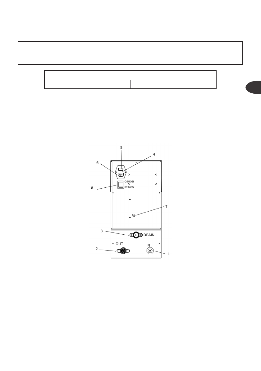
8 - USE
1. Inlet tting, 3/4BSP
2. Permeate tting, 3/4BSP
3. Concentrate tting, 3/4BSP
4. Fuse compartment
5. Main switch
6. Power supply cable socket
7. Pump adjustment hole
8. Osmosis diverter / Bypass

- 14 -
Basic operation
The systems of the DP series deliver water with an automatic osmosis management.
Water delivery is controlled by a maximum pressure switch inside the machine. When the
water demand ceases (for example, when the tap is closed on the permeate pipe), the
pressure rises up to the tripping value of the pressure switch (2.5 bar), and the control unit
will stop water delivery.
When there is a water demand (for example, when the tap is opened on the permeate
pipe), the pressure drops and the pressure switch will send a command for water delivery
to the control unit.
See the ELECTRONICS MANAGEMENT chapter for further details.
Emergency bypass
The versions with bypass function integrate a system which, if the system is locked, re-routes
the entire input water directly to the output by opening the solenoid valve. Doing so, even
if not treated, water can be delivered while waiting for technical support.
To pass from standard mode (osmosis) to emergency mode (bypass), activate the diverter
valve (8) bringing it to the bypass position.
NOTE:The bypass circuit is also protected by the fuse. If the system does not supply water
even after the bypass function is enabled, the fuse may need to be replaced.
Anti-ooding
The machine is equipped with an anti-ooding system, which can detect leaks in the
machine and will immediately stop water delivery. The system cannot detect and block
ooding from leaks outside the machine. If necessary, install management and control
devices for external ooding.
The manufacturer
cannot be held liable for any ood damage caused by leaking compo-
nents outside the machine.
- 15 -
English
9 - MAINTENANCE
For all technical and operational issues, please contact the manufacturer's Tech-
nical Support Division.
Installation and maintenance should be carried out to standard by specialist
technicians, in particular in compliance with this manual, pursuant to Ministerial
Decree no. 25 of 7 February 2012 and, where relevant, with provisions in Ministerial
Decree no. 37 of 22 January 2008.
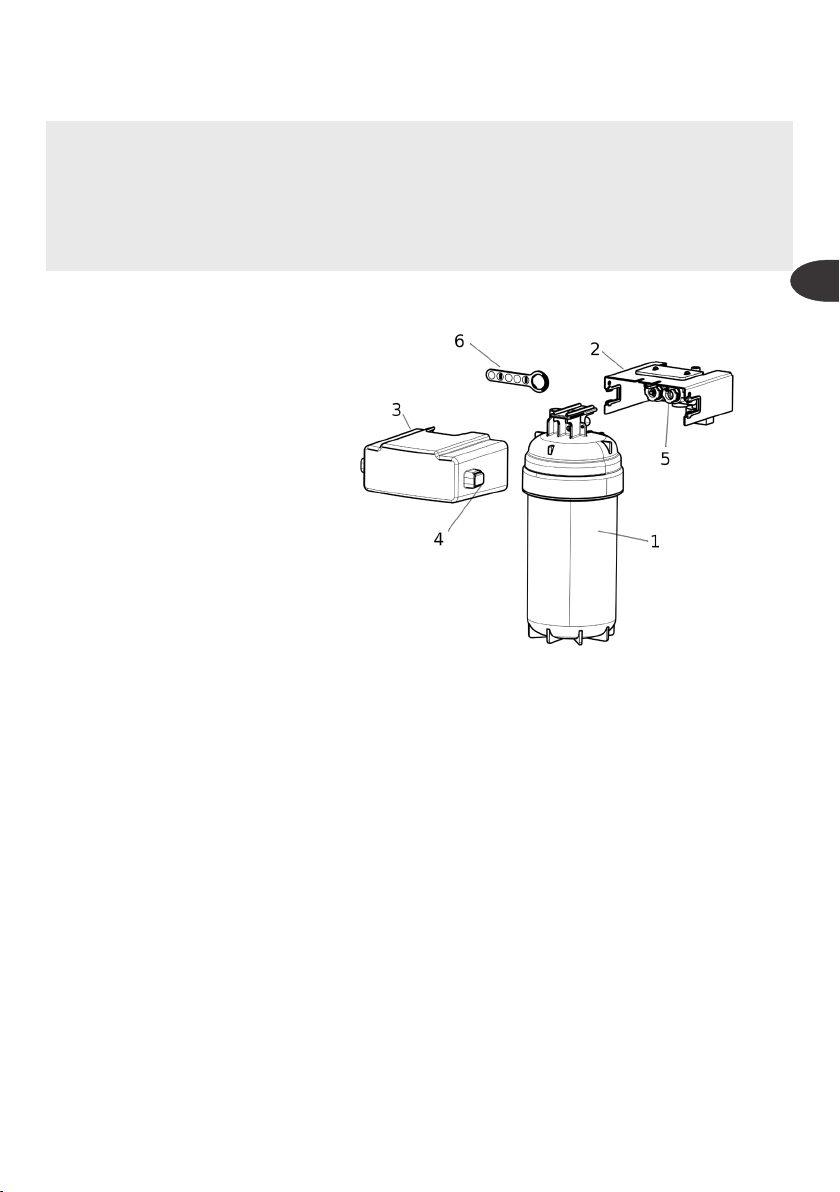
Procedure for pre-lter replacement and sanitisation
1. Filter
2. Head
3. Box
4. Unlocking keys
5. O-ring seat
6.
O-ring lock removal key
For lter replacement, proceed as
follows
Turn off the electrical power supply
to the system; for the SLIM ver
-
sions, close the shut-off valve of
the water supply circuit.
1. Press the buttons to remove the
lock box.
2. Remove the exhausted lter, sliding it horizontally.
3. Prepare the new lter, removing the seal.
4. Position the new lter, inserting it in the head guides.
5. Position the lock box, pushing it up to end of stroke, ensure the buttons have clicked
into position (you will hear a click)
6. Record the replacement in the maintenance table of this manual or by using the RO-
Check app.
7. To sanitise the system, you must use a FC500 Puro cartridge. This cartridge, as well as
the ltering medium with activated carbon, contains a sanitising product (Troclosene) with
an optimal quantity to perfectly sanitise the system. Simply replace the cartridge, start
the system and dispense water for 15 minutes. Discard the water. In this time interval,
the sanitising substance will be released for an appropriate time to have an optimal
action.At the same time, the system will be rinsed, eliminating the sanitising substance.
Having completed the cartridge procedure, the activated carbon ltering function will
start until the next replacement.

- 16 -
IMPORTANT
After the sanitisation procedure, use a measuring kit to check the concentration of
free chlorine in the permeate water.The concentration permitted for drinking water
may vary based on local standards. For some technical applications, the concen-
tration of chlorine permitted is under that permitted for drinking water.
See the technical data sheet and the safety data sheet, which can be requested
from the manufacturer.
If necessary, the O-rings can be replaced on the head.
1. Using the key (6), remove the clips of the O-ring (5) seat, rotating the clips counter-
clockwise
2. Remove the O-rings and replace with original spare parts, apply food-grade silicone
grease.
3. Re-assemble the clips on the seats (5) by applying a light pressure.
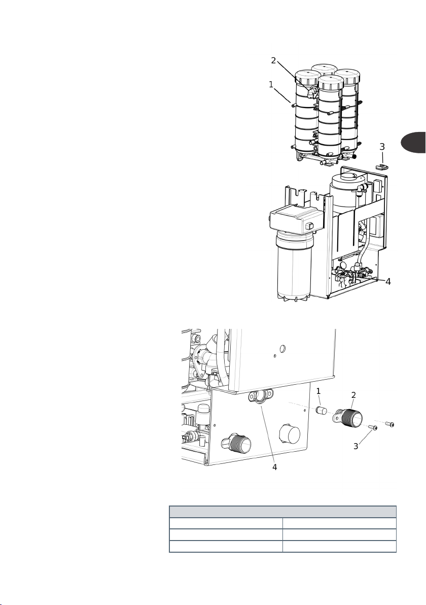
Procedure to replace the membranes
1. Vessel
2. Locking slider
3. Osmotic membrane 3012
4. Sealing plug
5. Vessel key
6. Closing plug
For lter replacement, proceed as follows
Turn off the electrical power supply to the system;
for the SLIM versions, close the shut-off valve of the
water supply circuit, and dismantle the vessel unit
of the system.
Always replace all the system membranes.
1. Remove the machine casing.
In the SLIM versions, the vessel unit must be
dismantled.
2. Dismantle the orange closing plugs, using the
locking slider.
3. Dismantle the vessel sealing plugs, rotating with the vessel key or, if not available, using
an adequate pin inserted in the plug eyelets.
4. Remove the exhausted membranes, clean the vessel inside
5. Position the new membranes
6. Assemble the vessel sealing plugs (if necessary, apply food-grade silicone grease),
assemble the closing plugs until the locking slider triggers
7. Start the system, deliver water for a complete air bleed. If necessary, adjust the pressure
of the pump and of the mixer (see the installation chapter)
- 17 -
English
8. Make sure the assembly is correct and that there
are no leaks before mounting the casing back on.
9. Record the replacement in the maintenance table
of this manual or by using the RO-Check app.
Dismantling procedure for the vessel unit
1. Vessel
2. L shaped connector
3. Locking clip
4. Permeate connector
To dismantle the vessel unit, simply remove the con
-
nection clip between the permeate duct (4) and the
vessel (1) and remove the vessel unit.
To reassemble the vessel unit, position its dovetails in
the casing slits, move delicately downwards ensuring
the L-shaped connectors and permeate connectors
are correctly inserted. Having done this, position the
locking clip (3) again.
Replacement procedure for the ow restrictor
1. ow restrictor
2. drainage outlet tting
3. screws
4. drainage manifold
To replace the ow restrictor, un
-
screw the screws (3), remove the
tting (2).
Remove the restrictor (1) from the
tting and place in the new tting.
Attention! Observe the correct
direction, O-ring outside the tting
(see image).
Re-assemble the screws, fasten
with reversible thread-locker.
FLOW RESTRICTOR TABLE
200 Blue
400 Purple
500 Grey
- 18 -
10 - ELECTRONIC MANAGEMENT
LCD CONTROL UNIT
Basic functions
• Delivery piloted by a pressure switch or with a tap with button
• Pump protection with a minimum pressure switch
• Flushing after each delivery
• Anti-residue every 6 hours
• Filter management based on time and litres delivered
• Detection of leaks and water ow obstructions on the machine
• Lock after 15 minutes of continuous delivery
• Conguration via dip switch
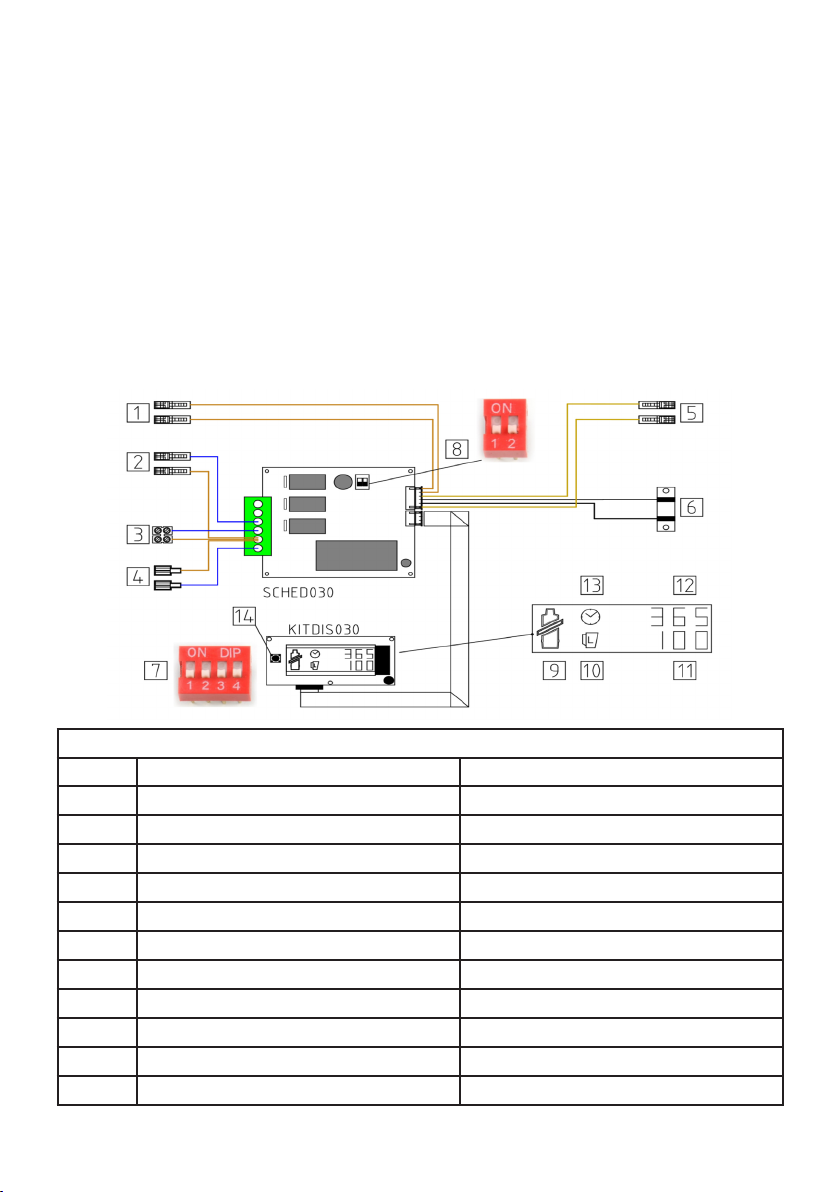
LEGEND
Num. Position / connection Description
1 Minimum pressure switch Brown cables with faston 6.3
2 Solenoid valve Brown / blue cables with faston 6.3m
3 Pump motor connection Brown / blue cables with terminal board
4 220Vac power supply connection Brown/blue cable with faston 4.8m
5 Maximum pressure switch connection Yellow cables with faston 6.3m
6 Anti-flooding
White / black cables with welded sensor
7 Display board Configuration dip switch
8 Power board Configuration dip switch
9 LCD Icon - Exhausted filter
10 LCD Icon - Water delivery
11 LCD
Icon - Litres until filter change (in %)

- 19 -
English
12 LCD Icon - Time until filter change (in days)
13 LCD Icon - Timer
14 Display board Reset key (R)
FILTER MANAGEMENT
The board manages the lter. The capacity can be set based on the quantity of water processed
and the time past (365 days).
When the lter runs out, the icon (9) will be ashing, the board can lock or not, based on the
conguration (see conguration section).
To reset, switch the machine off and on, keeping key R (14) pressed. The machine will respond
with three consecutive beeps.
Key R (14) is also used to display certain parameters of the equipment. In particular, if pressed
during the machine on status, the following will be displayed in sequence: lter ow rate, LCD
board rmware version, power board rmware version.
CONFIGURATION
(8) POWER BOARD
OFF ON
Dip switch 1 Cable (1) : button tap Cable (1) : minimum pres-
sure switch
Dip switch 2 - -
(7) LCD BOARD
OFF ON
Dip switch 1 Not used Not used
Dip switch 2 2xFc130 FC500
Dip switch 3 NO Filter alarm lock Filter alarm lock
Dip switch 4 15 min lock NO 15 min lock
TABLE OF ALARMS
NAME LCD BACKLIGHT RESET
Litres lter alarm Filter icon, L, zero
ashing Red Reset procedure
Time lter alarm Filter icon, Clock
zero ashing Red Reset procedure
Flooding “Flood” displayed Red Restart
15 minutes lock 15 Red Restart
Low pressure L.P. Red Automatic

- 20 -
RO-CHECK SYSTEM
The control unit can manage both reverse osmosis machines, HORECA machines, with
a minimum pressure switch, and household appliances.
Basic functions
• Delivery piloted by a pressure switch
• Pump protection with input pressure transducer
• Pump pressure transducer with alarms
• Conductivity reader with alarms
• Permeate ow reader with alarms
• Flushing after each delivery
• Anti-residue every 6 hours
• Filter management based on time and litres delivered
• Detection of leaks and water ow obstructions on the machine
• Conguration via the RO-Check app
LEGEND
Num. Position / connection Description
1 Solenoid valve Brown / blue cable with faston 6.3mm
2 Motor Brown / blue cable with terminal board
3 Electrical power supply Brown/blue cable with faston 4.8m
4 Pump pressure transducer Connector cable RAST 2.5
5 Input pressure transducer Connector cable RAST 2.5
This manual suits for next models
7
Table of contents
Popular Water Filtration System manuals by other brands

Premier
Premier 500320 UV-3 Installation, operation and maintenance manual

Cuckoo
Cuckoo CP-ADR031UW user guide

GCTek
GCTek AquaBead instructions

Viqua
Viqua Sterilight S80 owner's manual

APSWATER
APSWATER RO10D1 OPERATING AND INSTALLATION Manual

Vestergaard
Vestergaard LifeStraw PEAK Series Cleaning instructions


