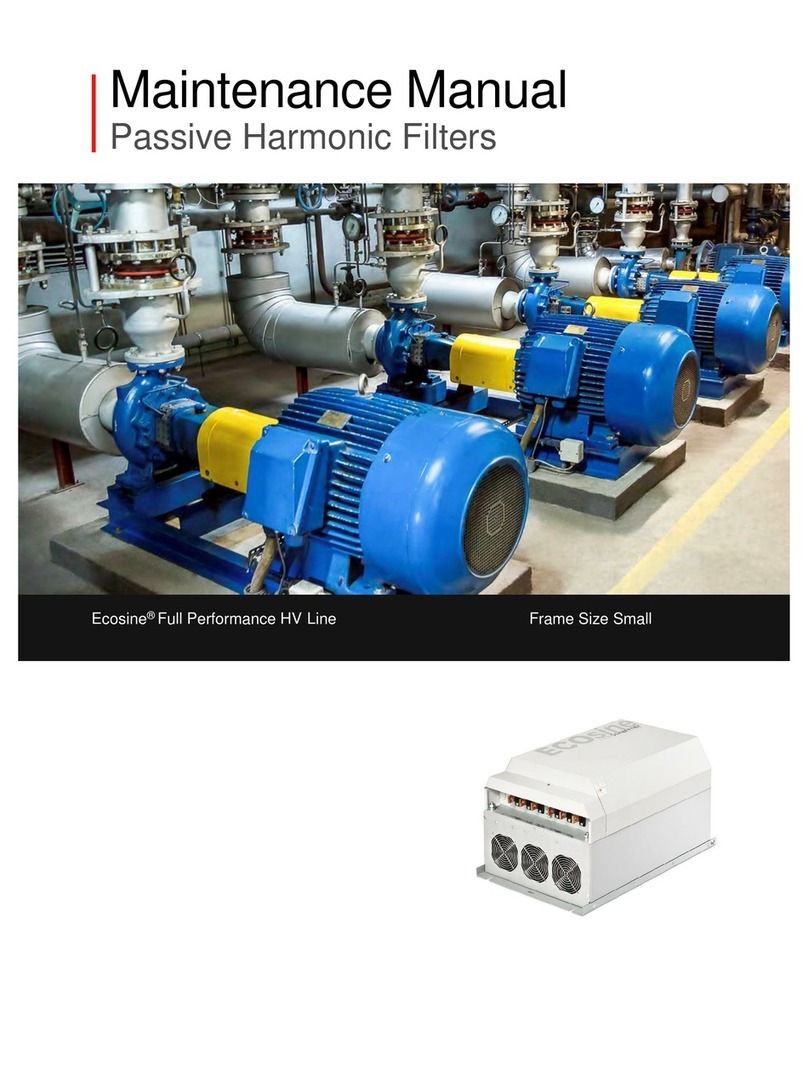
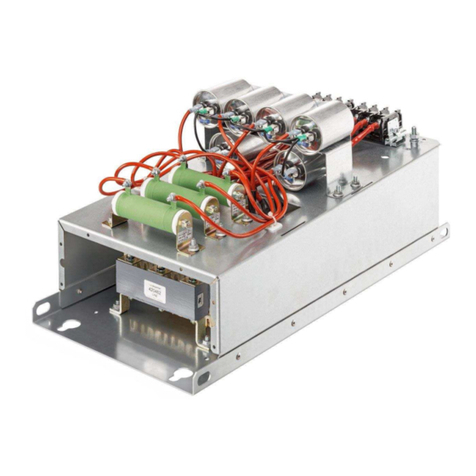
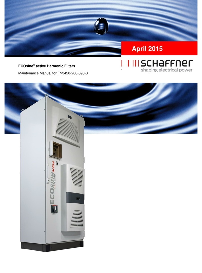
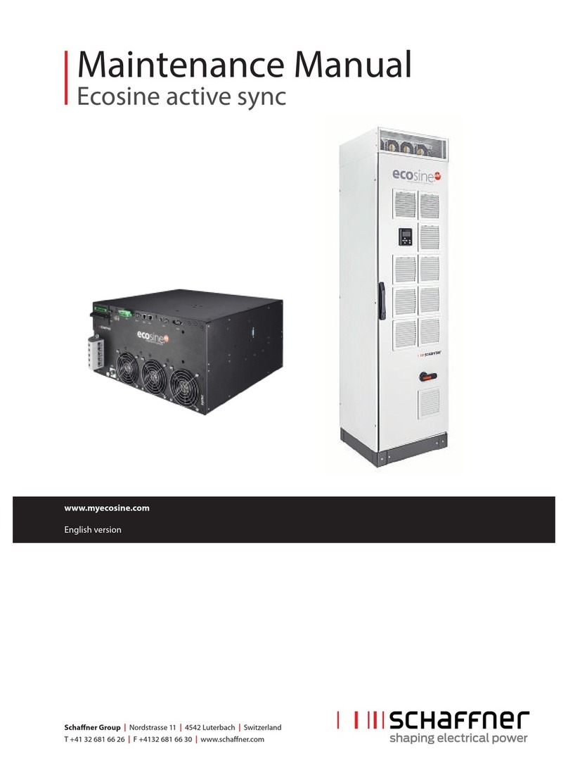
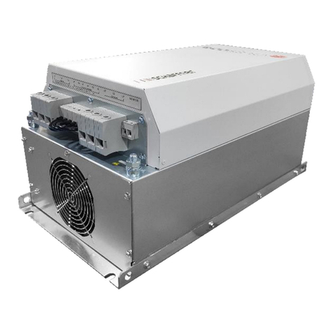
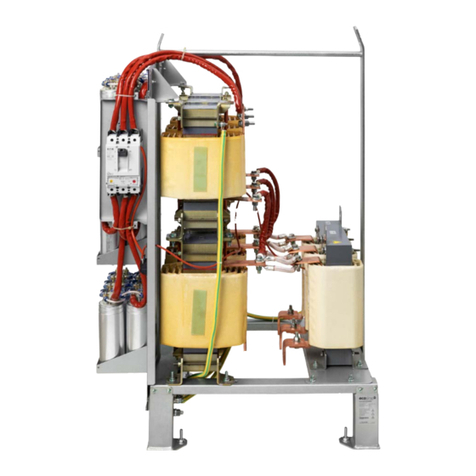
Schaffner ECOsine active FN3420-030-3 Series User manual

August 2015
ECOsine®active Harmonic Filters
Operating and Installation Instructions (V6)


®All rights reserved, even and especially in cases of proprietary rights applications.
We also retain sole power of disposal, including all rights relating to copying, transmission
and dissemination.
Revision: 6 (August 2015)
The most current edition of these instructions (PDF format) can be obtained from your con-
tact of the Schaffner sales organization and on the Internet at www.schaffner.com or
www.myecosine.com
Other technical documentation of our products is also available in the download area of our
website.
Valid for firmware version:
From V02.08.19 on
(For firmware version, see parameter P010)
Meaning of firmware version number:
V XX.xx.xx –hardware release, downwards incompatible
V xx.XX.xx –function version
V xx.xx.XX –small compatible changes
Document name:
Operating and Installation Instructions ECOsine active Rev6.pdf
Version history
Revision
Date
Description
6
August 2015
New air inlet design FN3430-200/250/300-400-4
5
April 2015
Updates on dimensional drawings and technical information, derating charts
added, maintenance schedule added, ECOsine®active with GL added, firm-
ware version V02.07.19 added
4
October 2013
Firmware description V02.08.xx to V02.08.17, ECOsine®active for 200V and
690V, cooling system from date of delivery calendar week 14/2013
3
March 2011
Firmware version V02.07.xx added
Editorial revisions
2
June 2009
Dimensional drawings ECOsine®active 100/120.
Drilling templates ECOsine®active 100/120 updated.
1
February 2009
First edition


5 ECOsine®active Harmonic Filters –Operating and Installation Instructions
Table of Contents
1General Safety Instructions 13
1.1 Intended use 14
1.2 Personnel qualification 15
1.3 Environmental conditions / Exclusion of warranty 16
2Introduction 18
2.1 Functions of the active filter 19
2.2 Principle of operation 20
2.3 About these instructions 21
2.4 Type plate 22
2.5 Type code 23
3Installation and Electrical Connection 24
3.1 Transport requirements ECOsine® active FN34xx-200/250/300-xxx-x 25
3.2 Commissioning after longer storage 26
3.3 Cooling circuit (ECOsine®active FN34xx-200/250/300-xxx-x) 27
3.3.1 Integrated cooling circuit with heat exchanger LNKS-8 28
3.3.2 Information on commissioning the cooling system 30
3.3.3 Water collection tray with drain tube 32
3.3.4 Interior air cooling system SK3305.xxx 33
3.3.5 System messages via LED display –SK3305.1xx with basic rules: 34
3.3.6 System messages via display –SK3305.5xx with comfort control 35
3.4 Dimensional drawings 38
3.4.1 Dimensional drawings ECOsine®active FN3420-030/050-xxx-3 38
3.4.2 Dimensional drawings ECOsine®active FN3430-030/060-xxx-4 40
3.4.3 Dimensional drawings ECOsine®active FN3420-100/120-xxx-3 42
3.4.4 Dimensional drawings ECOsine®active FN3420-100/120-480-3-GL 44
3.4.5 Dimensional drawings ECOsine®active FN3430-100/120-400-4 46
3.4.6 Dimensional drawings ECOsine®active FN3420-200/250/300-480-3 48
3.4.7 Dimensional drawings ECOsine®active FN3430-200/250/300-400-4 50
3.4.8 Dimensional drawings ECOsine®active FN3420-200-690-3 52
3.4.9 Dimensional drawings ECOsine®active FN3420-200-690-3-UL 54
54
3.5 Position of the connecting terminals 56
3.5.1 Connecting terminals ECOsine®active FN3420-30/50-xxx-3 56
3.5.2 Connecting terminals ECOsine®active FN3430-30/60-xxx-4 57
3.5.3 Connecting terminals ECOsine®active FN3420-100/120-xxx-3 58
3.5.4 Connecting terminals ECOsine®active FN3430-100/120-400-4 59
3.5.5 Connecting terminals ECOsine®active FN34xx-200/250/300-4xx-x 60
3.5.6 Connecting terminals ECOsine®active FN3420-200-690-3 61
3.6 External fuse protection 62
3.6.1 Recommended external mains fuse 62
3.6.2 External fuse protection for UL conformity 62

ECOsine®active Harmonic Filters –Operating and Installation Instructions 6
3.6.3 Devices with integrated fuse 63
3.7 Connection of ac mains (X1) 64
3.7.1 Connection of 3-wire devices 65
3.7.2 Connection of 4-wire devices 65
3.8 Component layout plan 66
3.8.1 Component layout plan FN3420-30/50-xxx-3 66
3.8.2 Component layout plan FN3430-30/60-xxx-4 67
3.8.3 Component layout plan FN3420-100/120-xxx-3 68
3.8.4 Component layout plan FN3430-100/120-400-4 69
3.8.5 Component layout plan FN34xx-200/250/300-4xx-x 70
3.8.6 Component layout plan FN3420-200-690-3 71
3.9 Connection of the external current transformers (X2) 72
3.9.1 Current transformers specification 72
3.9.2 Current transformer specification for UL conformity 74
3.9.3 Current transformer connection for operation of one ECOsine®active 74
3.9.4 Current transformer connection for parallel operation of several ECOsine®
active 76
3.9.5 Current transformer terminals on the active filter (X2) 78
3.9.6 Grounding of the current transformers 79
3.9.7 Checking current transformers rotating field 80
3.9.8 Checking current transformers phase assignment 81
3.10 Connection of the external interfaces 83
3.10.1 Overview 83
3.10.2 RS485 (X4) serial service interface 83
3.10.3 Digital inputs and outputs (X5) 84
3.10.4 Ethernet (X6) 86
3.10.5 Meaning of status LED 86
4Commissioning 87
4.1 Integrated display and keypad 88
4.2 Information screen 89
4.3 Parameter menu structure 90
4.4 Changing parameters 91
4.5 Commissioning procedure 92
4.6 Status messages 95
4.7 Error messages 97
4.8 Information for Schaffner Service 101
5Parameter list 102
5.1 Parameter groups P0xx, P1xx (read only) 103
5.2 Parameter groups P2xx, P3xx and P4xx (Commissioning parameters) 106
5.3 Parameter groups P4xx (setting of the compensation degree) 111
6AHF Viewer PC operating program 113
6.1 Operating system 114
6.2 Connecting to the PC 115

7 ECOsine®active Harmonic Filters –Operating and Installation Instructions
6.2.1 Connection via RS485 115
6.2.2 Connection via Ethernet 117
7Technical Data 119
7.1 General technical data 120
7.1.1 General technical data 400V / 480V and 200V / 240V 120
7.1.2 General technical data 500V / 690V 121
7.1.3 Maximum output current for harmonics 122
7.2 Device-specific data for ECOsine®active with mains voltage 200V / 240V 123
7.2.1 Device-specific data for ECOsine®active FN3430-030-200-4 123
7.2.2 Device-specific data for ECOsine®active FN3420-50-200-3 125
7.2.3 Device-specific data for ECOsine®active FN3430-060-200-4 127
7.2.4 Device-specific data for ECOsine®active FN3420-100-200-3 129
7.3 Device-specific data for ECOsine®active with mains voltage 400V / 480V 131
7.3.1 Device-specific data for ECOsine®active FN3420-030-480-3 131
7.3.2 Device-specific data for ECOsine®active FN3430-030-400-4 133
7.3.3 Device-specific data for ECOsine®active FN3420-050-480-3 135
7.3.4 Device-specific data for ECOsine®active FN3430-060-400-4 137
7.3.5 Device-specific data for ECOsine®active FN3420-100-480-3 139
7.3.6 Device-specific data for ECOsine®active FN3420-100-480-3-GL 141
7.3.7 Device-specific data for ECOsine®active FN3430-100-400-4 143
7.3.8 Device-specific data for ECOsine®active FN3420-120-480-3 145
7.3.9 Device-specific data for ECOsine®active FN3420-120-480-3-GL 147
7.3.10 Device-specific data for ECOsine®active FN3430-120-400-4 149
7.3.11 Device-specific data for ECOsine®active FN3420-200-480-3 151
7.3.12 Device-specific data for ECOsine®active FN3430-200-400-4 153
7.3.13 Device-specific data for ECOsine®active FN3420-250-480-3 155
7.3.14 Device-specific data for ECOsine®active FN3430-250-400-4 157
7.3.15 Device-specific data for ECOsine®active FN3420-300-480-3 159
7.3.16 Device-specific data for ECOsine®active FN3430-300-400-4 161
7.4 Device-specific data for ECOsine®active with mains voltage 500V / 690V 163
7.4.1 Device-specific data for ECOsine®active FN3420-200-690-3 163
8Maintenance 165
8.1 Cleaning of the ventilation grilles 166
8.2 Refilling the coolant 167
8.3 Maintenance plan ECOsine®active FN3420-30/50-480-3 168
8.4 Maintenance plan ECOsine®active FN3430-30/60-400-4 169
8.5 Maintenance plan ECOsine®active FN3420-100/120-480-3 170
8.6 Maintenance plan ECOsine®active FN3430-100/120-400-4 171
8.7 Maintenance plan ECOsine®active FN3420-200/250/300-480-3 172
8.8 Maintenance plan ECOsine®active FN3430-200/250/300-400-4 173
8.9 Maintenance plan ECOsine®active FN3420-200-690-3 174
9Declarations of Conformity 175
9.1 ECOsine®active FN34xx-30/50/60/100/120/200/250/300-xxx-x 176

9 ECOsine®active Harmonic Filters –Operating and Installation Instructions
Index of Tables
Table 1: Use of symbols, terms, and designations 21
Table 2: Type code 23
Table 3: Transport requirements 25
Table 4: Preventative formation in case of longer storage: 26
Table 5: Formation instructions for DC link capacitors 26
Table 6: Technical data of cooling system 29
Table 7: System messages cooling unit SK3305.1xx 34
Table 8: System messages cooling unit SK3305.5xx 37
Table 9: Installation clearances ECOsine®active FN3420-030/050-xxx-3 39
Table 10: Installation clearances ECOsine®active FN3430-030/060-xxx-4 41
Table 11: Installation clearances ECOsine®active FN3420-100/120-xxx-3 43
Table 12: Installation clearances ECOsine®active FN3420-100/120-480-3-GL 45
Table 13: Installation clearances ECOsine®active FN3430-100/120-400-4 47
Table 14: Installation clearances ECOsine®active FN3430-200/250/300-400-4 49
Table 15: Installation clearances ECOsine®active FN34xx-200/250/300-xxx-x 51
Table 16: Installation clearances ECOsine®active FN3420-200-690-3 53
Table 17: Installation clearances ECOsine®active FN3420-200-690-3-UL 55
Table 18: Recommended external ac mains protection 62
Table 19: Fuse types required for UL conformity 62
Table 20: Devices with integrated fuse 63
Table 21: Connection cross sections and tightening torque mains connection 64
Table 22: Current transformer specification 73
Table 23: Power consumption of the current transformer lines valid for copper wires 73
Table 24: Example of a current transformer with UL conformity 74
Table 25: X2 terminal strip –connection terminals for external current transformers 78
Table 26: Cable cross section external current transformers 78
Table 27: Assignment of the digital inputs and outputs 84
Table 28: Key functions 88
Table 29: Information screen 89
Table 30: ECOsine®active menu structure 90
Table 31: Status messages of ECOsine®active 96
Table 32: Error messages of ECOsine®active 100
Table 33: Overview of the parameter groups 102
Table 34: Parameters P0xx to P1xx 105
Table 35: Parameters P2xx to P410 (basic commissioning parameters) 110
Table 36: Parameters P411 to P434 (adjust degree of compensation) 112
Table 37: AHF Viewer prerequisites 114
Table 38: Interface converter specifications RS485 115
Table 39: Recommended galvanic isolation interface converter USB –RS485 115
Table 40: Pin assignment of connecting cable interface converter –ECOsine®active 115
Table 41: Parameters for the interface configuration RS 485 116
Table 42: Parameters for interface configuration 118
Table 43: General technical data ECOsine®active series 400V/480V and 200V/240V 120

ECOsine®active Harmonic Filters –Operating and Installation Instructions 10
Table 44: General technical data ECOsine®active series 500V / 690V 121
Table 45: Technical data ECOsine®active FN3430-030-200-4 123
Table 46: Technical data ECOsine®activeFN3420-50-200-3 125
Table 47: Technical data ECOsine®active FN3430-060-200-4 127
Table 48: Technical data ECOsine®active FN3420-100-200-3 129
Table 49: Technical data ECOsine®active FN3420-030-480-3 131
Table 50: Technical data ECOsine®active FN3430-030-400-4 133
Table 51: Technical data ECOsine®active FN3420-050-480-3 135
Table 52: Technical data ECOsine®active FN3430-060-400-4 137
Table 53: Technical data ECOsine®active FN3420-100-480-3 139
Table 54: Technical data ECOsine®active FN3420-100-480-3-GL 141
Table 55: Technical data ECOsine®active FN3430-100-400-4 143
Table 56: Technical data ECOsine®active FN3420-120-480-3 145
Table 57: Technical data ECOsine®active FN3420-120-480-3-GL 147
Table 58: Technical data ECOsine®active FN3430-120-400-4 149
Table 59: Technical data ECOsine®active FN3420-200-480-3 151
Table 60: Device-specific data for ECOsine®active FN3430-200-400-4 154
Table 61: Technical data ECOsine®active FN3420-250-480-3 156
Table 62: Technical data ECOsine®active FN3430-250-400-4 157
Table 63: Technical data ECOsine®active FN3420-300-480-3 159
Table 64: Technical data ECOsine®active FN3430-300-400-4 161
Table 65: Technical data ECOsine®active FN3420-200-690-3 164
Index of Figures
Fig. 1: Principle of operation of the ECOsine®active filter 20
Fig. 2: Cable transport scheme 25
Fig. 3: Cooling equipment (ECOsine®active FN34xx-200/250/300-xxx-x) 27
Fig. 4: Cooling system –main components 28
Fig. 5: Cooling system –hydraulic plan 29
Fig. 6: Pressure and filling level indication of the cooling circuit 29
Fig. 7: Terminals for auxiliary power supply 30
Fig. 8: Terminals for auxiliary power supply 31
Fig. 9: Drain-tube of water tray 32
Fig. 10: Drain duct at the cabinet bottom 32
Fig. 11: Connection option for condensate drain at the interior air cooler 33
Fig. 12: Dimensional drawings ECOsine®active-030/050-xxx-3 38
Fig. 13: Drilling template ECOsine®active FN3420-030/050-xxx-3 39
Fig. 14: Dimensional drawings ECOsine®active FN3430-030/060-xxx-4 40
Fig. 15: Drilling template ECOsine®active FN3430-030/060-xxx-4 41
Fig. 16: Dimensional drawings ECOsine®active FN3420-100/120-xxx-3 42
Fig. 17: Drilling template ECOsine®active-100/120-xxx-3 43
Fig. 18: Dimensional drawings ECOsine®active FN3420-100/120-480-3-GL 44
Fig. 19: Drilling template ECOsine®active FN3420-100/120-480-3-GL 45

11 ECOsine®active Harmonic Filters –Operating and Installation Instructions
Fig. 20: Dimensional drawings ECOsine®active FN3430-100/120-400-4 46
Fig. 21: Drilling template ECOsine®active FN3430-100/120-400-4 47
Fig. 22: Dimensional drawings ECOsine®active-200/250/300-480-3 (with mounted
base 100 mm)* 48
Fig. 23: View from below ECOsine®active FN3420-200/250/300-480-3 49
Fig. 24: Dimensional drawings ECOsine®active FN3430-200/250/300-400-4 (with
mounted base 100 mm)* 50
Fig. 25: View from below ECOsine®active FN3430-200/250/300-400-4 51
Fig. 26: Dimensional drawings ECOsine®active FN3420-200-690-3 (with installed
base 100 mm)* 52
Fig. 27: View from below ECOsine®active FN3420-200-690-3 53
Fig. 28: Dimensional drawings ECOsine®active FN3420-200-690-3-UL (with mounted
base 100 mm)* 54
Fig. 29: View from below ECOsine®active FN3420-200-690-3-UL 55
Fig. 30: Position of the electrical connecting terminals ECOsine®active -30/50-xxx-3 56
Fig. 31: Connection ECOsine®active FN3420-30/50-xxx-3 56
Fig. 32: Position of the electrical connecting terminals ECOsine®active
FN3430-30/60-xxx-4 57
Fig. 33: Connection ECOsine®active FN3430-30/60-xxx-4 57
Fig. 34: Position of the electrical connecting terminals ECOsine™ active
FN3420-100/120-xxx-3 58
Fig. 35: Connection ECOsine®active FN3420-100/120-xxx-3 58
Fig. 36: Position of the electrical connecting terminals ECOsine®active
FN3430-100/120-400-4 59
Fig. 37: Connection ECOsine®active FN3430-100/120-400-4 59
Fig. 38: Position of the electrical connecting terminals ECOsine®active
FN34xx-200/250/300-4xx-x 60
Fig. 39: Connecting bar neutral wire ECOsine®active -200/250/300-xxx-4 61
Fig. 40: Position of electrical connecting terminals ECOsine®active
FN3420-200-690-3 61
Fig. 41: Connection of 3-wire devices 65
Fig. 42: Connection of 4-wire devices 65
Fig. 43: Component layout plan ECOsine®active FN3420-30/50-xxx-3 66
Fig. 44: Component layout plan ECOsine®active FN3420-30/60-xxx-4 67
Fig. 45: Component layout plan ECOsine®active FN3420-100/120-xxx-3 68
Fig. 46: Component layout plan ECOsine®active FN3430-100/120-400-4 69
Fig. 47: Component layout plan ECOsine®active FN34xx-200/250/300-4xx-x 70
Fig. 48: Component layout plan ECOsine®active FN3420-200-690-3 71
Fig. 49: CT wiring for operation of one ECOsine®active 74
Fig. 50: CT installation on load side for operation of one ECOsine®active 75
Fig. 51: CT installation on mains side for operation of one ECOsine®active 75
Fig. 52: CT wiring for parallel operation of up to five ECOsine®active devices 76
Fig. 53: CT installation on load side for parallel operation of several ECOsine®active
devices 77
Fig. 54: X2 terminal strip –ext. current transformers 78
Fig. 55: Grounding of the current transformers (optional) 79
Fig. 56: Checking rotating field of current and voltage 80

ECOsine®active Harmonic Filters –Operating and Installation Instructions 12
Fig. 57: Phase of current and voltage is correct 81
Fig. 58: Phase of current and voltage is shifted through 180°. 81
Fig. 59: Current transformer 1 phase-is shifted through 180°. 82
Fig. 60: Current transformers of phase 1 and 3 are interchanged 82
Fig. 61: Position of the control terminals 83
Fig. 62: Functional connection of digital input/outputs 84
Fig. 63: X5 terminal strip –digital inputs and outputs (ECOsine®active
30/50/60/100/120-xxx-x) 85
Fig. 64: X5a terminal strip –digital inputs and outputs (ECOsine®active
200/250/300-xxx-x) 85
Fig. 65: Integrated ON-OFF switch (ECOsine®active 200/250/300-xxx-x) 85
Fig. 66: Meaning of status LED 86
Fig. 67: Display and keypad 88
Fig. 68: Example for cos φ control (cos φ on mains side is kept in the hatched target
range) 109
Fig. 69: AHF viewer basic screen 113
Fig. 70: Current limit curve 122
Fig. 71: Derating ECOsine®active FN3430-30-200-4 124
Fig. 72: Derating ECOsine®active FN3420-50-200-3 126
Fig. 73: Derating ECOsine®active FN3430-60-200-4 128
Fig. 74: Derating ECOsine®active FN3420-100-200-3 130
Fig. 75: Derating ECOsine®active FN3420-30-480-3 132
Fig. 76: Derating ECOsine®active FN3430-30-400-4 134
Fig. 77: Derating ECOsine®active FN3420-50-480-3 136
Fig. 78: Derating ECOsine®active FN3430-60-400-4 138
Fig. 79: Derating ECOsine®active FN3420-100-480-3 140
Fig. 80: Derating ECOsine®active FN3420-100-480-3-GL 142
Fig. 81: Derating ECOsine®active FN3430-100-400-4 144
Fig. 82: Derating ECOsine®active FN3420-120-480-3 146
Fig. 83: Derating ECOsine®active FN3420-120-480-3-GL 148
Fig. 84: Derating ECOsine®active FN3430-120-400-4 150
Fig. 85: Derating ECOsine®active FN3420-200-480-3 152
Fig. 86: Derating ECOsine®active FN3430-200-400-4 154
Fig. 87: Derating ECOsine®active FN3420-250-480-3 156
Fig. 88: Derating ECOsine®active FN3430-250-400-4 158
Fig. 89: Derating ECOsine®active FN3420-480-3 160
Fig. 90: Derating ECOsine®active N3430-300-400-4 162
Fig. 91: Derating ECOsine®active FN3420-200-690-3 164

13 ECOsine®active Harmonic Filters –Operating and Installation Instructions
1 General Safety Instructions

ECOsine®active Harmonic Filters –Operating and Installation Instructions 14
1.1 Intended use
The ECOsine®active harmonic filter is used for active compensation of reactive power and
harmonic content and for load balancing.
Please ensure that no compensation systems, which are not detuned, are connected to the
same grid. Otherwise interactions between ECOsine®active and these compensation sys-
tems may occur.
DANGER
Dangerous voltage
Risk of death due to short circuits and electric shock if the
active filter is opened improperly. The discharge time of
the intermediate circuit after disconnecting from the
mains can be more than 5 minutes.
All interventions involving opening the device cover or remov-
ing or installing the connection cable may only be performed
by qualified personnel.
WARNING
High-frequency interferences
In a residential environment, high-frequency interferences
could occur, which necessitate interference suppression.
Note
Please note that there are additional manuals for some product variants. For the latest
versions of these manuals go to www.schaffner.com
It particularly applies to types FN3420-100/120-400-3-GL, please observe the special
EMC-Filter Manual for these types (ECOsine EMC Filters for Applications with GL)

15 ECOsine®active Harmonic Filters –Operating and Installation Instructions
1.2 Personnel qualification
Installation of the ECOsine®active filter, inspections for proper operation, and certain trou-
bleshooting measures may only be performed by qualified personnel. All other measures
may be performed by people who have read these instructions.

ECOsine®active Harmonic Filters –Operating and Installation Instructions 16
1.3 Environmental conditions / Exclusion
of warranty
This document classifies groups of environmental parameters and their severities to which
ECOsine®active harmonic filters are subjected when mounted for stationary use at weather
protected locations under use conditions, including periods of erection work, down time,
maintenance and repair. The lifetime of electronic equipment is depending on the environ-
mental conditions they are exposed to. Especially in harsh environments lifetime is reduced
due to the corrosiveness of the atmospheric environment. Generally corrosion in micro or
power electronics depends on several variants such as the package type, materials in-
volved, assembly processes, moisture, inorganic and organic contaminants, atmospheric
pollutants, temperature, thermal stress and electrical bias. To increase the lifetime
Schaffner provides all ECOsine®active filters with the ability to work within pollution degree
2 (PD2) and does use coated PCB’s according to IEC61721-3-3. Schaffner standard PCB
construction complies with class 3C2. Please carefully read the provided information and
check if your application fulfills the required specifications as Schaffner expressly points
out that the manufacturer's warranty shall lapse with immediate effect if ECOsine®ac-
tive harmonic filters are transported, stored, installed or operated outside their pub-
lished specifications.
IMPORTANT!
ECOsine®active harmonic filters (AHF) listed below are IP20
or IP54 devices to be installed in an environment in compli-
ance with the requirements named in this document.
All AHF must be installed in a clean, dry location, e.g. in suf-
ficiently ventilated or air conditioned electric cabinets or
closed electric rooms. Contaminants such as oils, liquids,
corrosive vapors, abrasive debris, dust and aggressive gas-
es must be kept out of the filter enclosure.
WARNING: Conductive dust may cause damage to ECO-
sine®active harmonic filters. Ensure that installation site
of AHF is free of conductive dust.
Products
FN3420 series, 3-wire filters, models 30…300A
FN3430 series, 4-wire filters, models 30…300A
Overvoltage class
(EN50178)
ECOsine®active are designed according to EN 50178
overvoltage class III
Storage environmental
specifications
(IEC 60721-3-1, EN50178)
Climate conditions for storage class 1K3:
Temperature range: -25°C to +55°C
I
Relative humidity: < 95%, no condensation
I
Atmospheric pressure: 70KPa to 106KPa
I

17 ECOsine®active Harmonic Filters –Operating and Installation Instructions
Transportation environ-
mental specifications
(IEC 60721-3-2, EN50178)
Climate conditions for transport class 2K3:
Temperature range: -25°C to +70°C
I
Relative humidity: < 95%, no condensation
I
Atmospheric pressure: 70KPa to 106KPa
I
Operation environmental
specifications
(IEC 60721-3-3, EN50178)
Climate conditions for operation class 3K3:
Temperature range: 0°C to +40°C
I
Relative humidity: < 95%, no condensation
I
Atmospheric pressure: 70KPa to 106KPa
I
Degree of pollution
(IEC 61010, EN50178)
Pollution conditions for operation class PD2
Corrosive levels
(IEC 60721-3-3)
Corrosive levels for storage, transport and operation Class
3C2(3):
Applies to locations with normal levels of contaminants,
I
experienced in urban areas with industrial activities
Levels:
I
Environmental parameter
Units(1)
Class 3C2(2)
Mean value
Max value
Sea salt
Salt mist
Sulphur dioxide
ppm
cm3/m3
0.3
0.11
1.0
0.37
Hydrogen sulphide
ppm
cm3/m3
0.1
0.071
0.5
0.36
Chlorine
ppm
cm3/m3
0.1
0.034
0.3
0.1
Hydrogen chloride
ppm
cm3/m3
0.1
0.066
0.5
0.33
Hydrogen fluoride
ppm
cm3/m3
0.01
0.012
0.03
0.036
Ammonia
ppm
cm3/m3
1.0
1.4
3.0
4.2
Ozone
ppm
cm3/m3
0.05
0.025
0.1
0.05
Nitrogen oxides
ppm
cm3/m3
0.5
0.26
1.0
0.52
(1) The values given in cm3/m3have been calculated from the values given
in mg/m3and refer to a temperature of 20 °C and a pressure of 101,3 kPa.
The table uses rounded values.
(2) Mean values are expected long-term values. Maximum values are limit
or peak values, occurring over a period of time of not more than 30 min
per day.
(3) IEC 60721-3-3 is only applied to the coated PCB covered areas and not the entire
device. The unprotected areas, such as connections, terminations and exposed magnetics,
may not survive these exposure levels over time.

ECOsine®active Harmonic Filters –Operating and Installation Instructions 18
2 Introduction

19 ECOsine®active Harmonic Filters –Operating and Installation Instructions
2.1 Functions of the active filter
The ECOsine®active filter enables:
Reduction of the current THDI
Reduction of the harmonic current contentI
Compensation of reactive power and an improvement of the power factor cos φ, induc-I
tive and capacitive
Display of mains current and voltageI
Load balancingI

ECOsine®active Harmonic Filters –Operating and Installation Instructions 20
2.2 Principle of operation
The ac mains current, which is drawn by a non-linear load, is measured by ECOsine®active
either directly or indirectly via external current transformers. The harmonic content and
reactive power components are detected and processed in a digital control structure. The
active filter continually generates a compensating current that offsets the harmonic content
and reactive current in the load, so the ac mains only has to provide the minimum
fundamental in phase current.
Compensating current
Mains supply
Load
Neutral
Fig. 1: Principle of operation of the ECOsine®active filter
The active filter instantly adapts to all changes in the load and the systems harmonic con-
tent spectrum, in order to be able to optimally respond at any time.
This manual suits for next models
17
Table of contents
Other Schaffner Water Filtration System manuals

Schaffner
Schaffner FN 3025 Instruction sheet

Schaffner
Schaffner EMC Instruction sheet

Schaffner
Schaffner Ecosine FN3446 Series Operating manual

Schaffner
Schaffner Ecosine max FN 3470 Operating manual

Schaffner
Schaffner Ecosine FN34 Series User manual

Schaffner
Schaffner ECOsine User manual

Schaffner
Schaffner FN5420 Operating manual

Schaffner
Schaffner ecosine FN3540 User manual

Schaffner
Schaffner FN5420 Operating manual

Schaffner
Schaffner FN 6840-25-113-E0XXR Operating manual