USER TIPS INSTALLATION
1
2
3331
6
7
7
8
5
4
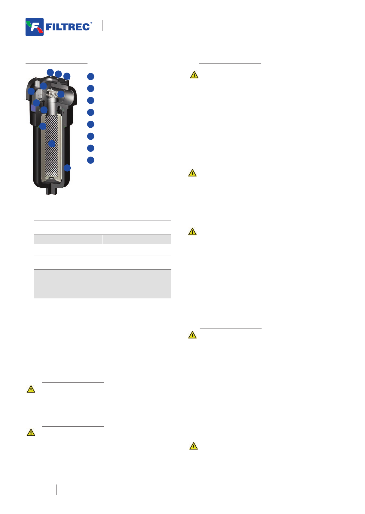
FILTER HEAD
2INDICATOR PORT
3FIXING HOLES
4BY- PASS VALVE
5FILTER ELEMENT
6FILTER BOWL
7SEAL KIT
8IDENTIFICATION LABEL
1. the IN and OUT ports must be connected to the
hoses in the correct flow direction (an arrow
shows on the filter head (1)
2. the filter housing should be preferably mounted
with the bowl (6) downward
3. secure to the frame the filter head (1) using the
threaded fixing holes (3)
4. verify that no tension is present on the filter after
mounting
5. enough space must be available for filter
element replacement
6. the visual clogging indicator must be in a easily
viewable position
7. when a electrical indicator is used, make sure
that it is properly wired
8. never run the system with no filter element fitted
9. keep in stock a spare FILTREC filter element for
timely replacement when required
OPERATION
1. the filter must work within the operating
conditions of pressure, temperature and
compatibility given in the first page of this data
sheet
2. the filter element must be replaced as soon as
the clogging indicator signals at working
temperature (in cold start conditions, oil
temperature lower than 30°C, a false alarm can
be given due to oil viscosity)
3. If no clogging indicator is mounted, replace the
element according to the system manufacturer’s
recommendations
WARNING
Make sure that Personal Protective Equipment (PPE) is
worn during installation and maintenance operation.
DISPOSAL OF FILTER ELEMENT
The used filter elements and the filter parts dirty of oil
are classified as “Dangerous waste material”: they
must be disposed according to the local laws by
authorized Companies.
MAINTENANCE
1. make sure that the system is switched off and
there is no residual pressure in the filter
2. unscrew the bowl (6) by turning it anti-clockwise
and remove it
3. remove the dirty element (5)
4. fit a new FILTREC element (5), verifying the part
number, particularly concerning the micron
rating; open its plastic protection on the open
end side and insert it onto the spigot in the filter
head, then remove completely the plastic
protection
5. clean carefully the bowl; check the O-rings (7)
conditions and replace if necessary
6. lubricate the bowl's thread (6) and screw it by
hand in the filter head (1) by turning it
clockwise
7. screw in the bowl to stop
8. the used filter elements cannot be cleaned
and re-used
INDICATOR TIGHTENING TORQUE
V05/E05/V08/E08 50 Nm
SPARE SEAL KIT PART NUMBER
NBR FKM
F280-D120/24/21 06.021.00090 06.021.00135
F280-D140/41/43 06.021.00095 06.021.00137
F280 SERIES 6/8
HYDRAULIC DIVISION F280 SERIES


