Better Water MediPac User manual
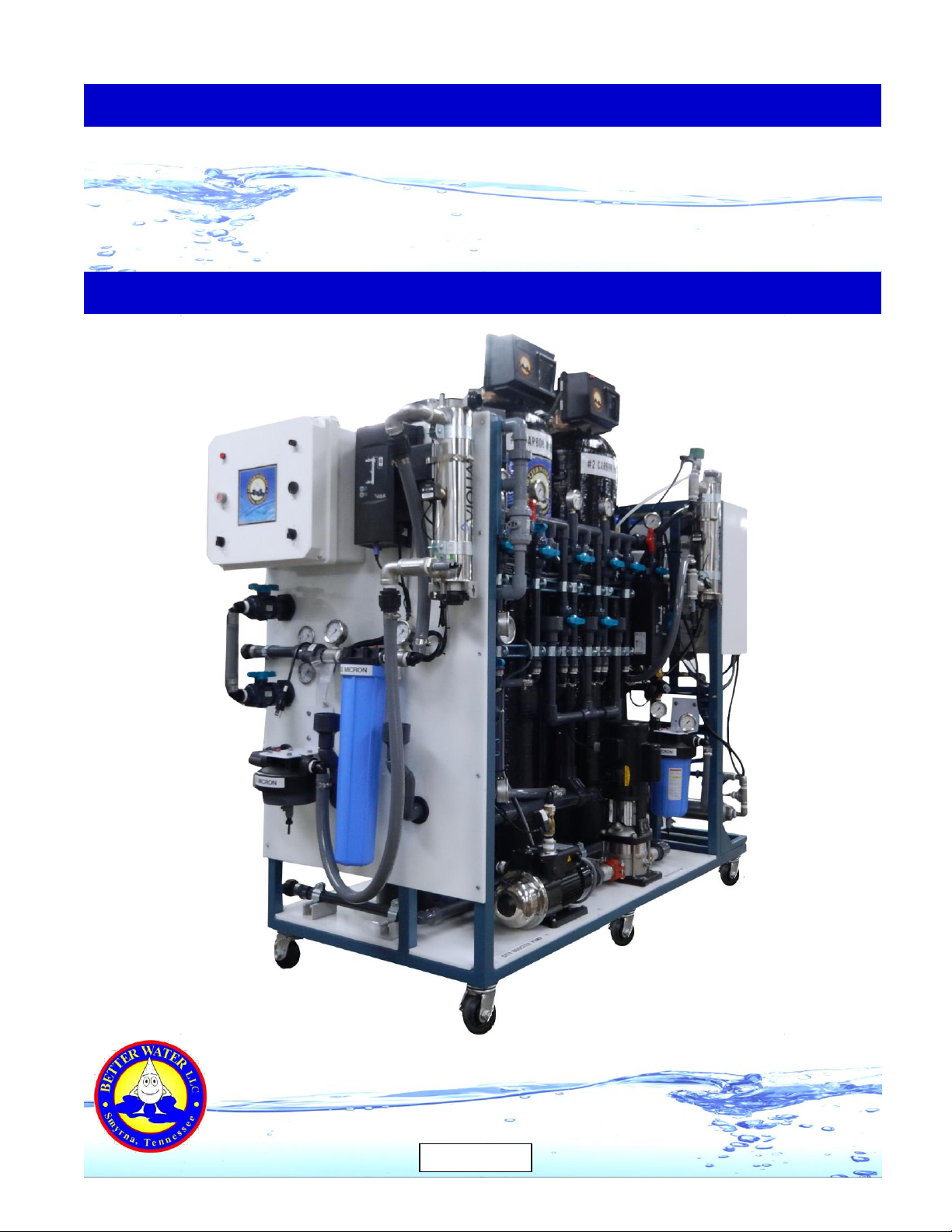
MediPac
(Tank Feed)
Operator Manual
Better Water LLC
rev. Jun 2016

Better Water LLC. All rights reserved.
The content of this manual is the intellectual property of Better Water LLC. It is furnished for the
express use by Better Water LLC, their customers and dealers, for informational use only for operation,
service, and internal training. No part of this manual may be reproduced for distribution, sale, or any
intent other than previously described without the written permission of Better Water LLC. This manual
is subject to change without notice. Better Water LLC assumes no responsibility or liability for any error
or inaccuracies that may appear in this documentation.
Adobe and Acrobat are registered trademarks of Adobe Systems, Inc.
Better Water LLC; 698 Swan Dr; Smyrna, TN 37167; www.betterwater.com

rev. Jun 2016
MediPac, Tank Feed Operator Manual
TABLE OF CONTENTS
Our Company ……………………………………………………………………………………... 01
- Contact Us ……………………………………………………………………………………….. 01
- Technical Phone Support ………………………………………………………………………. 01
- Technical Support Info Online …………………………………………………………………. 01
- Specific Contacts ………………………………………………………………………………... 02
Introduction ………………………………………………………………………………………… 02
Warnings …………………………………………….…………………………………………….. 03
Cautions ……………………………………………….…………………………………………… 03
General Requirements and Specifications ……..……………………………………………… 04
Models ……………………………………………………………………………………………… 05
Important Information for Support ………………………………………………………………. 05
Product Description …………………………..……………………………………………………06
Detailed View of the MediPac
- Pre-Treatment Side …………………………………….……………………………………….. 07
- RO End …………………………………………………………………………………………… 07
- Post-Treatment End …………………………………………………………………………….. 08
System Components:
- MediPac Control Box …………………………………………………………………………… 09
- Pre-Treatment; Pressure Gauges …………………………………………………………….. 09
- Pre-Treatment; Thermometer …………………………………………………………………. 10
- Pre-Treatment; Blending Valve ……………………………………………………………….. 10
- Pre-Treatment; City Booster Pump ……………………………………………………………. 11
- Pre-Treatment; Automatic Control Valves ……………………………………………………. 11
- Pre-Treatment; Interlock Wiring System ……………………………………………………… 12
- Pre-Treatment; Water Softener ……………………………………………………………….. 13
- Pre-Treatment; Brine Tank …………………………………………………………………….. 14
- Pre-Treatment; Carbon Media Filtration ……………………………………………………… 15
- Pre-Treatment; Ultra-Violet Irradiation (Pre-RO) …………………………………………….. 16
- Pre-Treatment; Particulate Filtration Cartridge (10” Big Blue, 5 micron filter) …………… 17
- 1232 RO ………………………………………………………………………………………….. 18
- Post-Treatment; Repress Pump ………………………………………………………………. 19
- Post-Treatment; Ultra-Violet Irradiation (Post-RO) ………………………………………….. 20
- Post-Treatment; Pyrogen Cartridge (20”, .03 micron ultra-filter) ………………………….. 21
- Post-Treatment; Particulate Filtration (10” Big Blue, 5 micron filter) ……………………… 22
- Divert-to-Drain, Wall-Mounted …………………………………………………………………. 23
- Storage Tank and Level Control System ……………………………………………………... 24
- Remote Alarm Box ……………………………………………………………………………….25
- Disinfect Tank ……………………………………………………………………………………. 25
Operation
- General Operation ………………………………………………………………………………. 26
- Valves Legend …………………………………………………………………………………… 27
- Daily Start-Up ……………………………………………………………………………………. 30
- Monitoring Procedures ………………………………………………………………………….. 31
- Daily Shutdown ………………………………………………………………………………….. 31

rev. Jun 2016
MediPac, Tank Feed Operator Manual
Cleaning & Disinfecting
- General Cleaning and Disinfecting Overview ………………………………………………… 32
- Cleaning and Disinfecting Agents …………………………………………………………….. 33
- Disinfecting and Cleaning Procedure ……………………………………………………….... 34
- Disinfect/Clean the RO …………………………………………………………………………. 34
- Disinfect the Post-Treatment, Storage Tank, and Distribution Loop ……………………… 37
- Sanitizing the Sanitary Sample Ports …………………………………………………………. 39
Water Leak Detector ………….………………………………………………………………….. 40
Switching to Temporary DI …………………………………………………………………….. 41
System Maintenance
- General …………………………………………………………………………………………… 44
- Long Term Storage or Non-Use ……………………………………………………………….. 45
- Adjusting the Blend Valve Temperature Setting ……………………………………………...45
- Priming the City Booster Pump and Repress Pump ………………………………………… 47
- Change Particulate Filter Cartridges and Pyrogen Filter ……………………………………. 48
- Automatic Control Valves; Set Time of Day …………………………………………………. 49
- Automatic Control Valves; Set on Which Days to Regenerate/Backwash ……………….. 49
- Automatic Control Valves; Initiate a Manual Regenerate/Backwash ……………………… 49
- Automatic Control Valves; Changing Regenerate/Backwash Program Cycles ………….. 50
- Automatic Control Valves; Replacing Seals and Spacers ………………………………….. 51
Service Help
- MediPac, Post-Treatment End ………………………………………………………………….53
- MediPac; 1232 RO End ………………………………………………………………………… 54
- MediPac; Front-Side ……………………………………………………………………………..55
- MediPac Control Box (front view) ……………………………………………………………… 56
- MediPac Control Box (inside lid view) ………………………………………………………… 57
- MediPac Control Box (inside view) ……………………………………………………………. 58
Related Consumable and Replacement Items ……………………………………………..…. 59
Related Disinfectants & Cleaners ……..………………………………………………………… 61
Related Consumable Media ……………………………………………………………………... 62
Limited Warranty Terms and Conditions ……………………………………………………….. 63
Appendix A, Sample Quality Assurance Checklist ……………………………………………. 65
Appendix B, Bleach Use in the Post-Treatment Components (Tank-Feed Systems Only)…. 68
Appendix C, Calculations & Conversions
- Conversion Formulas …….……………………………………………………….…………….. 69
- Calculation for Area of Pipe Volume …………………………………………………………...69
- 3 Feet per Second Flow Velocity Rates ……………………………………………………….70
Better Water LLC; 698 Swan Dr; Smyrna, TN 37167; www.betterwater.com
Better Water LLC; rev. Jun 2016
Page 1 of 72
MediPac, Tank-Feed Operator Manual
0
Our
Company
Contact
Us
Technical
Phone
Support
Technical
Support
Info
Online
Better Water LLC is a leading integrated manufacturer of water treatment
equipment and components for the industrial, commercial and institutional
markets.
Located in Smyrna, Tennessee,
Better Water LLC continues its history
of manufacturing and distribution of
equipment specifically designed for the
renal dialysis market.
Founded in 1971, Better Water LLC has
built a reputation for solving our
customers' toughest problems with high
quality products and unmatched service.
Better Water LLC Technical Support:
698 Swan Dr Phone (615) 355-6063, press "1"
Smyrna, TN 37167 Email support@betterwater.com
Phone (615) 355-6063 Customer Service:
Fax (615) 355-6065 Phone (615) 355-6063, press "3"
Email customerservice@betterwater.com
Support is available regarding all Better Water LLC systems,
24 hours a day,7 days a week.
Normal business hours are Monday through Friday from
8:00 am until 3:30 pm, Central Standard Time (excluding holidays)
Call (615) 355-6063, press "1" for Technical Support
Emergency assistance is available after normal business hours (including
holidays) by calling (615) 708-8627.
Our website, www.betterwater.com, which is updated
frequently, contains a wealth of technical support information on the
SUPPORT tab and includes:
Operator and Service Manuals
Consumables and Accessories Lists
Technical Service Bulletins
For your convenience there are also online forms for placing Orders
and requesting Returned Goods Authorization. These are Adobe
forms that can be downloaded and either faxed or emailed to us.

Better Water LLC; rev. Jun 2016
Page 2 of 72
MediPac, Tank-Feed Operator Manual
Introduction
Specific
Contacts
Technical Support Phone (615) 355-6063, option “1”
Email support@betterwater.com
To Place an Order Fax (615) 355-6065
(purchase orders) Email orders@betterwater.com
Phone (615) 355-6063
Customer Service Phone (615) 355-6063, option “2”
(returns) Fax (615) 355-6065
Website www.betterwater.com
Helpful information and forms that can be found on our website:
- Operator & Service Manuals
- Technical Service Bulletins
- Consumables and Replacement Parts List
- Brochures
- Order Form
- Return Goods Authorization Request Form
The Better Water LLC MediPac System is manufactured to the utmost
quality. With proper operation, maintenance, and care, this device
should give you years of reliable service.
Before starting you should first read and have a thorough understanding
of this entire Operator Manual. It describes in detail the steps and
procedures for safe usage of this system.
This device was designed and built with consideration for the
information that has been provided to use on the current product water
requirements at your site of operation.
This device was designed and built as a complete water treatment
system to produce high-quality water for hemodialysis, and is not
intended for any other application.
Once the this device has been delivered, it is the responsibility of the
Medical Director to ensure that it is used, monitored, and maintained in
such a manner so as to satisfy all applicable standards. Guidelines and
other related information are available from:
- Food and Drug Administration (FDA)
- National Association of Nephrology Technicians/Technologists (NANT)
- Association for the Advancement of Medical Instrumentation (AAMI)
NOTE concerning pictures in this manual:
Pictures of devices and components may vary slightly due to product
changes, and therefore should be for general reference only.
Information concerning their use, functionality, or replacement will not
differ unless noted.
Better Water LLC; rev. Jun 2016
Page 3 of 72
MediPac, Tank-Feed Operator Manual
WARNINGS
1. It is unsafe to operate or service this device without first reading and understanding the entire
Operator's Manual. Keep this manual and other associated documentation for future reference.
2. Misuse, improper operation, and/or improper monitoring of this system could result in serious
injury, death, or other serious reactions to patients undergoing hemodialysis treatment.
3. Misuse, improper use or handling of disinfectants and chemical cleaning solutions could result
in serious injury or even death. You must comply with the information contained in the Material
Safety Data Sheet (MSDS) for the chemical being used.
4. To avoid electrical shock hazard, do not operate this device when the covers or panels are
removed.
5. ELECTROMAGNETIC INTERFERENCE: This device can create and radiate
radio frequency energy and may cause harmful interference if not installed
according to the manufacturer's instructions.
CAUTIONS
1. When used as a medical device, federal law restricts this device to sale by or on the authority
of a physician. Per CFR 801.109 (b)(1).
2. Improper operation of this device could result in a low or no-flow alarm on the dialysis
machines.
3. Misuse or improper operation of this device will void any warranty.
4. Where water is mentioned, unless otherwise noted, it must be AAMI standard quality water.
5. Plumbing connections must adhere to local statutes and any facility codes.
6. Do not remove any Caution, Warning or any other descriptive labels from the device.
7. Do not operate this device in an explosive environment or in the presence of flammable
materials.
8. Do not use this device to store, mix or transfer flammable liquids. Movement or vibrations
during shipment may cause connections to loosen.
9. Do not operate this unit in an environment where temperatures may be below 50oF or above
90oF.
10. This device should not be used for purposes outside the device’s stated applications,
specifications or limitations.

Better Water LLC; rev. Jun 2016
Page 4 of 72
MediPac, Tank-Feed Operator Manual
GENERAL REQUIREMENTS & SPECIFICATIONS
SPACE:
- The system should be level and located as close as possible to the point of use.
- Minimum space required Length 92” x Width 38” x Height 82”.
- Additional space will be required for the water softener’s brine tank, determined by the size of
the tank.
- Additional space will be required for the storage tank if a Tank-Feed system, determined by the
size of the tank.
- The floor must be capable of supporting up to 2500 lbs.
- Space considerations should include adequate operator access.
WATER SUPPLY CONNECTION:
- Requires a 1” female NPT threaded water connections, both hot and cold, with an adjacent
shut-off valve.
FEED WATER SUPPLY REQUIREMENTS:
- The importance of monitoring and controlling the municipal tap water cannot be underestimated.
The pre-treatment feed water must meet the following parameters:
- Pressure: 30 psi (minimum) to 50 psi (maximum); 40 psi (optimum)
- The minimum pressure must be maintained with water flowing at the maximum required
flow-rate. This is dynamic pressure; not static pressure.
- Flow Rate: 4 gallons per minute
- Temperature: 50° to 90° F
DRAIN REQUIREMENT:
- Requires a sanitary drain capable of discharging 15 gpm (gallons per minute) or better.
ELECTRICAL CONNECTION:
- Two electrical outlets, 115 vac, single phase, with 20 amp breakers
Better Water LLC; rev. Jun 2016
Page 5 of 72
MediPac, Tank-Feed Operator Manual
MODELS
There is only one model of the tank-feed MediPac based around the 1232 RO.
Model
Specifications
EQMEDIPAC-2880-TF-10
Tank Feed, 2880 gpd
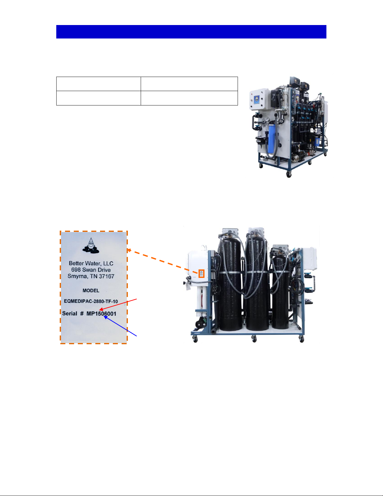
IMPORTANT INFORMATION FOR SUPPORT
Adhered to the side of each MediPac’s RO Control Box is a label containing important information
relating to the specific unit, and details both the Model and Serial Number. Both of these
pieces of information are very important in obtaining support, determining warranty, and properly
servicing this unit. Please have this information available if you contact Technical Support.
The first four numbers in the serial number denote the year and month the device was
manufactured. In the example above the unit, was produced in 2015, in the month of June.
“15” –Year
“06” - Month
Better Water LLC; rev. Jun 2016
Page 6 of 72
MediPac, Tank-Feed Operator Manual
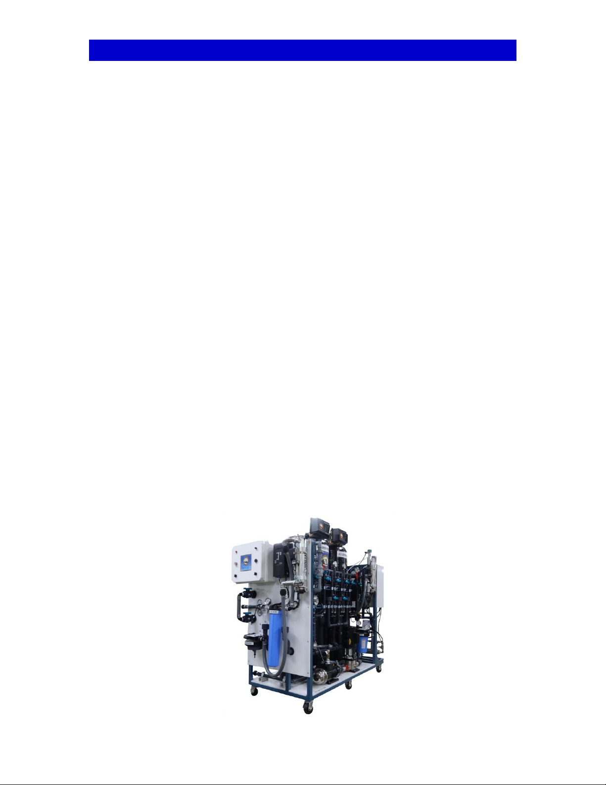
PRODUCT DESCRIPTION
The MediPac is designed to be a complete water system on a wheeled frame, which includes
Pre-Treatment components, a 1232 RO, and Post-Treatment components. All three of these
elements reside on a frame with the exception of the storage tank and brine tank. It designed to
support six to eight stations.
The Frame is constructed of welded steel with a durable powder-coat paint finish to reduce rust
and corrosion. The frame is mounted on sturdy casters for ease in moving should the need arise.
The MediPac Control Box is located on the left side (post-treatment end) of the rack, and both
controls and provides power to many of the MediPac components. It also contains the
components for a water leak detection system which will automatically close the main water
shutoff valve in the event a water leak is detected.
The Pre-Treatment portion of this unit is comprised of the following components:
- A Blend Valve to maintain the proper water temperature.
- A City Booster Pump to maintain adequate pressure for the system to operate.
- Carbon Filter Tanks (worker and polisher) to remove chlorine and chloramines.
- A Water Softener to reduce water hardness by removing heavy metals such as calcium and
magnesium from the water. Works in conjunction with a Brine Tank containing salt.
- An Ultra-Violet Light to reduce bacteria.
- A Sediment Filter for particulate and sediment filtration.
- There are also a Temperature Gauge, Pressure Gauges and Sample Ports for monitoring the
system’s operation.
The Reverse Osmosis unit is the 1232 RO, which resides on right side of the MediPac frame. It
consists of four membranes, and produces 2 gallons per minute RO water for the system.
The Post-Treatment portion of this unit is comprised of the following components:
- A Ultra-Violet Light to reduce bacteria.
- A 20” .03 Micron Filter for bacteria and pyrogen filtration.
- DI Connection points for use with DI Tanks.
- A 10” Big Blue 5 Micron Filter for Post-DI filtration.
- A Repressurization Pump to circulate water through the distribution loop.
- A Storage tank located near the unit is equipped with level controls to operate the RO.
- There are also a Flow-Meter, Pressure Gauges, and Sample Ports for monitoring the
system’s operation.
Better Water LLC; rev. Jun 2016
Page 7 of 72
MediPac, Tank-Feed Operator Manual
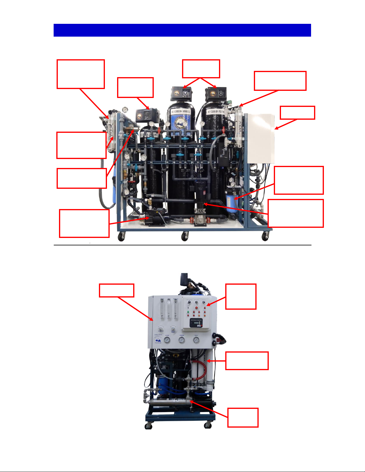
DETAILED VIEW of a MediPac, Front Side
DETAILED VIEW of a MediPac, RO End
Water
Softener
Carbon
Tanks
MediPac
Control Box
(behind UV)
1232 RO
Pre-Treatment
UV
Pre-Treatment
Blend Valve
1232 RO
RO
Control
Box
RO
Pump
Pre-Treatment
City Booster
Pump
RO
Membranes
Post-
Treatment
UV Light
Pre-Treatment
10” 5 micron
Filter
Post-Treatment
Repressurization
Pump
Better Water LLC; rev. Jun 2016
Page 8 of 72
MediPac, Tank-Feed Operator Manual
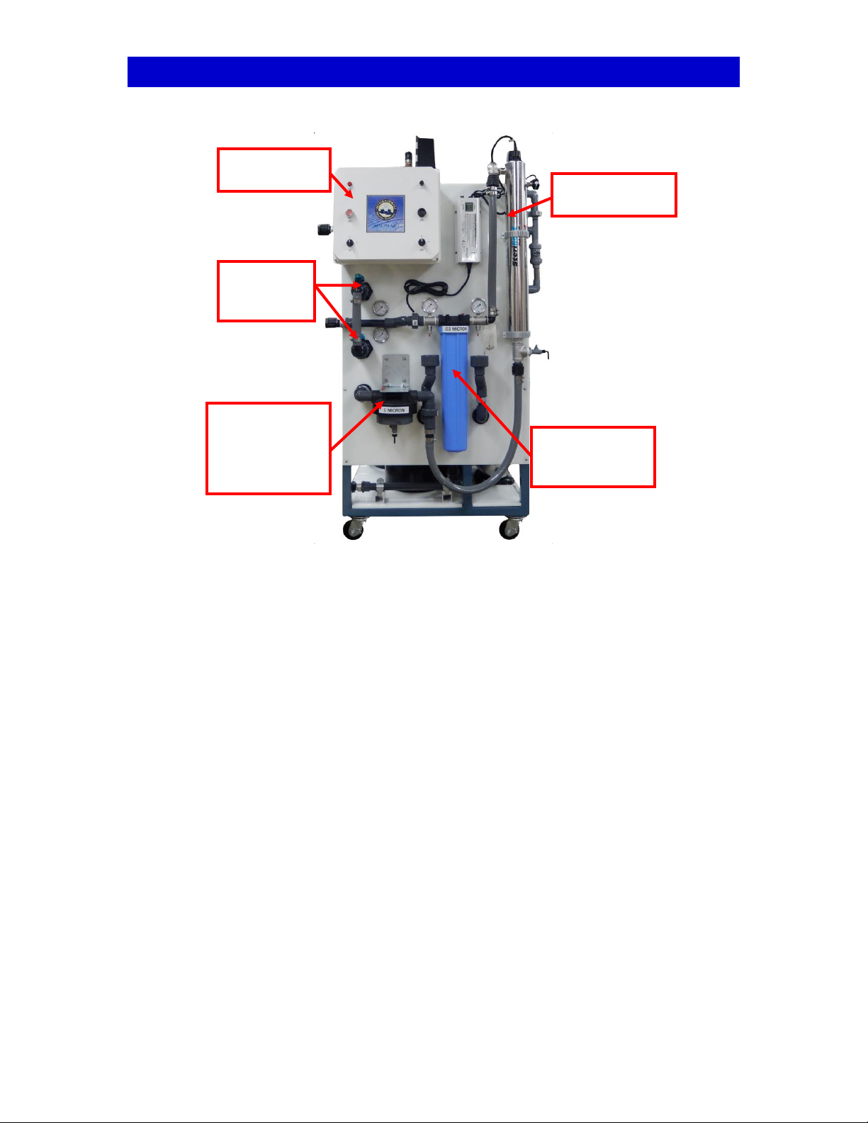
DETAILED VIEW of a MediPac, Post-Treatment End
MediPac
Control Box
Post-Treatment
UV
Post-Treatment
.03 micron
Filter
Post-Treatment
5 micron Filter
(Post-DI)
(shown with short
bowl)
DI
Connection
Header

Better Water LLC; rev. Jun 2016
Page 9 of 72
MediPac, Tank-Feed Operator Manual
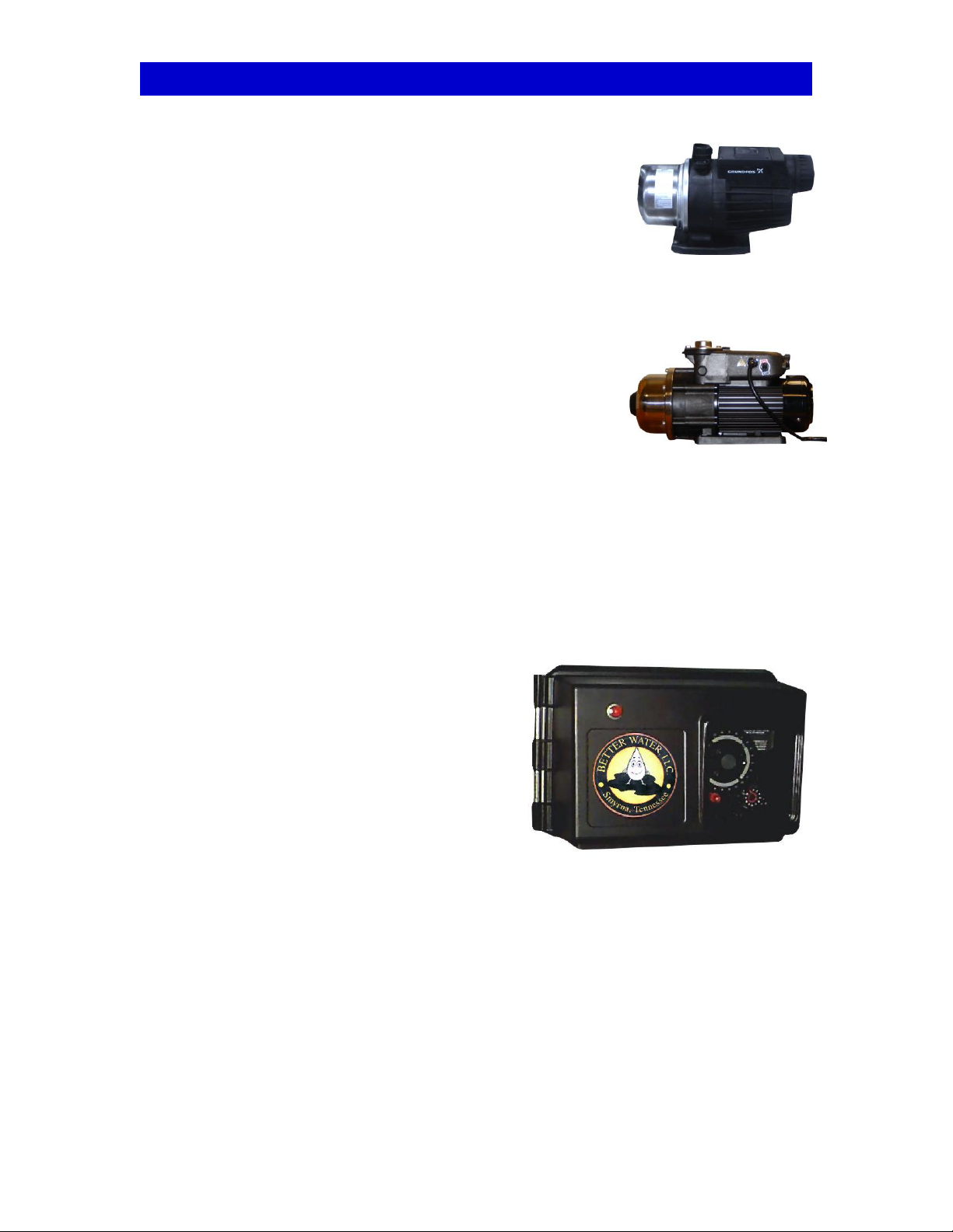
SYSTEM COMPONENTS: MediPac Control Box
DESCRIPTION:
The control box is a water-tight, chemical resistant box, containing electronic components needed
to control and provide power to many of the MediPac’s components.
The MediPac Control Box does the following:
- Facilitates the Level Controls from the RO and Storage
Tank
- Controls the Water Leak Detector and Alarm
- Controls the Repress Pump
- Controls the Pre-Treatment UV and its UV Dump Valve
- Provides power to the Post-Treatment UV
- Contains components of the water leak detector and will
alarm and close the main-water shutoff valve if a water leak
is detected.
Specific operating details are discussed later in this
manual.
SYSTEM COMPONENTS: PRE-TREATMENT; Pressure Gauges
DESCRIPTION:
The monitoring of components in any water treatment system depends highly
on monitoring the pressures before and after the component. Most
components in the system will have less than 15 psi normal differential
pressure. When this differential pressure rises toward or exceeds 15 psi, the
component will require attention to determine the problem or cause.
Differential Pressure or Delta Pressure (represented by the symbol ΔP) is equal
to the Inlet Pressure minus the Outlet Pressure when the RO is running.
ΔP = Inlet Pressure – Outlet Pressure. Example: If the #1 carbon filter is showing an inlet
pressure of 60psi and an outlet pressure of 55 psi, the Δ pressure is 5 psi. Under most
circumstances, the normal ΔP of most components will be less than 15 psi.
Most components in a Better Water LLC water system are supplied with gauges that will show the
pressure before and after the specific component. Gauges used before the RO will be made of
brass and stainless steel. Gauges used in and after the RO will be made of stainless steel only.
All gauges in the system will be 0-100 psi, dry (not glycerin filled), with a 1.5% accuracy.

Better Water LLC; rev. Jun 2016
Page 10 of 72
MediPac, Tank-Feed Operator Manual
SYSTEM COMPONENTS: PRE-TREATMENT; Thermometer
DESCRIPTION:
Maximum water production of the RO depends greatly on the temperature
of the feed water. Water that is too cold will require more pressure from the
RO pump to force it through the membranes, which will put undue stress on
them, causing the membrane pressure to rise. Water that is too hot can
cause damage to the membranes. If the water gets too hot, the RO will shut
down in a high feed temp alarm.
77° F is the temperature for optimum performance of the Better Water LLC.
RO. The pre-treatment system has a stainless steel, in-line temperature gauge located just after
the blend valve. This temperature gauge will monitor the blend valve to assure adequate water
temperature of the water being supplied to the RO. The blend valve will normally be set at
approximately 72-75°F.
SYSTEM COMPONENTS: PRE-TREATMENT; Blending Valve
DESCRIPTION:
The blending valve is an automatic, mechanical device that
instantly compensates for supply line temperature and
pressure changes to maintain the pre-selected temperature
of the feed-water. The manufacturer states that this device
complies with the requirements of Federal specifications
WW-P-541/7B and all other known standards, codes, and
specifications.
MONITORING REQUIREMENTS:
Daily: Verify the selected temperature range while the RO is running.
MAINTENANCE:
* See System Maintenance section for how to adjust the blend valve, thus affecting water
temperature.
NOTE: The manufacturer states that this device, “Fails safely on hot or cold supply failure of
thermal motor failure (when so specified) to shut down flow.” When feed water flow ceases, the
RO unit will shut down, producing a low feed pressure audible and visual alarm on the RO and on
any remote alarm locations.
Better Water LLC; rev. Jun 2016
Page 11 of 72
MediPac, Tank-Feed Operator Manual
SYSTEM COMPONENTS: PRE-TREATMENT; City Booster Pump
DESCRIPTION:
The city booster pump is a stainless steel, multi-stage,
centrifugal pump designed for continuous duty service.
The pump is powered by a 1 HP, single phase, 115 vac
motor. The pump starts automatically when there is a
demand for water. This pump is designed for boosting
water pressure for circulation service.
Pump models may vary between devices.
MONITORING REQUIREMENTS:
Daily: Monitored to ensure desired pressure is maintained.
MAINTENANCE:
* See System Maintenance section for priming instructions.
SYSTEM COMPONENTS: PRE-TREATMENT; Automatic Control
Valves
DESCRIPTION: All automatic backwashing filters
and softeners are equipped with automatic control
valves, which control the backwashing/regeneration
times, cycles, and frequencies for the specific filter it
operates. These feature a 7 day calendar time
clock and has an interlock feature to prevent the RO
from running while the filter is in backwash or
regeneration. (See Interlock Wiring System Section)
MONITORING REQUIREMENTS:
Daily: Verify the controller day, and time of day is
properly set.
MAINTENANCE:
- The seals and spacers in the valve should be changed every 3 to 5 years. This may have to be
done sooner if there is a malfunction of the device.
* See System Maintenance section.
part#
EQPUGR01905
City Boost Pump
Grundfos MQ Series
part#
EQPUWA00251
City Boost Pump
Walrus TQ-800

Better Water LLC; rev. Jun 2016
Page 12 of 72
MediPac, Tank-Feed Operator Manual
SYSTEM COMPONENTS: PRE-TREATMENT; Interlock Wiring
System
DESCRIPTION:
The interlock wiring system is a safety feature, incorporated into all Better Water LLC water
systems, is a low voltage (24 vac) lockout system designed to shut down the RO machine, if
running, or prevent the RO from running, when any filter or softener goes into backwash or
regeneration.
A 24 volt signal originates at the RO and is sent to each selected piece of pre-treatment
equipment in series, and the last piece of equipment is equipped with a “jumper” to return the
signal to the RO. When a filter or softener goes into backwash or regeneration mode, the signal
is redirected to a red light on the specific control valve, which illuminates to indicate the backwash
or regeneration mode of that piece of equipment. It also starts the city booster pump, and opens
the blend valve bypass. With this signal not being returned to the RO, the RO will not run or will
stop if running when the signal is broken. The interlock wiring system utilizes quick-connect
fittings on all connections.

Better Water LLC; rev. Jun 2016
Page 13 of 72
MediPac, Tank-Feed Operator Manual
SYSTEM COMPONENTS: PRE-TREATMENT; Water Softener
DESCRIPTION: Water softening consists of a single water softener to meet
system flow demands, reduction ratios, and user criteria. The water softener
in this system is commercial/industrial grade, automatic, and custom sized
to meet the demand.
The water softener in the system has a 7 day calendar time clock to
control regeneration. The controller can be set to regenerate at pre-set times
on specific days, giving the user maximum flexibility. The controller has an
interlock feature to prevent the RO from running during the regeneration cycle.
When regenerating a red light is illuminated as an indicator of this cycle and
the RO will not run due to the interlock.
The resin is a premium grade, strong acid cation for high flow rate condensate
demineralizing made from food-grade materials that meet FDA CFR 173.25
specifications. The water softener is regenerated with salt brine that is made
from quality, premium grade salt pellets specified for water softening and/or
conditioning. Do not use rock salt, as this form of salt carries impurities and
will tend to have adverse effects on your water pre-treatment system. For information
on about brine tanks, see the previous section titled “System Components: Brine Tanks”.
MONITORING REQUIREMENTS:
Daily: This device requires daily monitoring to insure the controller clock is properly set
Daily: Check pre and post-filter pressure, and ΔP (pressure drop) across it while the RO is
running
Daily: Check the salt level in the brine tank is greater than 50%
Daily: The hardness, measured post softener, should be tested daily while the softener is under
peak demand, usually late in the afternoon.
MAINTENANCE:
- The salt level in the brine tank should be filled periodically so it doesn’t fall below 50%.
- Better Water LLC recommends that tank media be changed every three years unless…
… otherwise specified by the medical director and/or company polices,
… or the hardness breakthrough is greater than 2 grains per gallon after two verified regeneration
cycles.
Water
Softener

Better Water LLC; rev. Jun 2016
Page 14 of 72
MediPac, Tank-Feed Operator Manual
SYSTEM COMPONENTS: PRE-TREATMENT; Brine Tank
DESCRIPTION:
The water softener includes a brine tank that holds the salt which produces
the brine solution for the regeneration of the water conditioning resin. The
brine tanks supplied with all Better Water LLC water softeners are made of a
non-corrosive, plastic with a plastic grid plate in the bottom to reduce or
eliminate “bridging” of the salt (see note below). On the inside of the tank is
a brine well which houses the brine valve. This brine valve is connected with
a 3/8” or larger brine line to a single or duplex softener. Only one brine tank
is required for a duplex system. This tube serves to draw the brine solution
out of the brine tank during the “brine draw” cycle, and also to refill the brine
tank during the “brine refill” cycle of the control valve.
Better Water, LLC utilizes three safety measures with the brine valve; First, located
on the bottom of the brine valve is an air check valve. This is a device incorporated
into the brine valve to stop the flow through the brine tube in case the brine level
drops to an insufficient level. This will prevent the control valve from drawing air
into the system. Second, the brine valve is equipped with a float valve on the top,
to prevent the brine tank from overfilling, in the event of a control valve malfunction, or in the
event of a power outage during the refill cycle. Thirdly, an overflow line is installed,
in the rare case of overflow; the excess will be routed to a suitable drain.
The brine tank should only be filled with quality, premium grade salt pellets
specified for water softening and/or conditioning. Do not use rock salt, as
this form of salt carries impurities and will tend to have adverse effects on your
water pre-treatment system.
NOTE: Bridging occurs in brine tanks when the salt sticks together to form one large solid mass
of pellets, or by the salt caking in a dry-salt brine tank which causes failure of the liquid or brine
beneath the dry salt to become saturated. The result of bridging is insufficient salt in the
regeneration solution to properly regenerate the cation resin.
Brine tanks are sized according to the size of the water softener, organic scavenger, and
dealkalizer vessels. Better Water LLC, primarily uses 2 sizes of brine tanks. 16” diameter and
smaller devices will be supplied with an 18” diameter brine tank. 20” and larger devices will be
supplied with a 24” brine tank. 30” and larger devices, although seldom used, can be supplied
with even larger brine tanks. On occasion, a customer will request a smaller brine tank, due to
space restrictions. Although adequate with some procedural modifications, this is not
recommended. A smaller brine tank will require salt filling more often.
MONITORING REQUIREMENTS:
Daily: Daily monitoring of the salt level in the brine tank is required, refilling as necessary.
MAINTENANCE:
- The salt level in the brine tank should be filled periodically so it doesn’t fall below 50%. The salt
level should be maintained above the water level in the tank. It is recommended that the salt
level to rise and fall over time, and not just “top off” on a daily basis, which will allow a good “turn-
over” of the salt in the tank.
NOTE: It takes a minimum of 3 to 4 hours to fully saturate the water in the brine tank after
refilling for maximum results.
Brine tanks should be emptied and cleaned annually, or more often if necessary.
Cutaway view
of brine tank

Better Water LLC; rev. Jun 2016
Page 15 of 72
MediPac, Tank-Feed Operator Manual
SYSTEM COMPONENTS: PRE-TREATMENT; Carbon Media
Filtration
DESCRIPTION:
Carbon filtration is based upon a naturally occurring phenomenon called
adsorption, in which molecules of a liquid or gas are trapped by either the
external or internal surface of a solid. Activated carbon has a very high
internal surface area and thus is an ideal material for adsorption. Raw water
quality can be improved with the removal of trace components.
Carbon filters are backwashed periodically (every other day) to expose
new adsorption sites in the media. After backwash, a down-flow rinse
prepares the media for service.
Carbon filtration consist of at least 2 properly sized pressure vessels (tanks)
which are filled with predetermined volumes of carbon. In most systems,
two properly sized, backwashable carbon filters are connected in series with
tank #1 adsorbing the entire load and tank #2 performing a polishing task
while providing a back-up capability.
Each carbon filter in the system has a 7 day calendar time clock to control backwashing. The
controller can be set to backwash at pre-set times on specific days, giving the user maximum
flexibility. The controller has an interlock feature to prevent the RO from running during the
backwash cycle. When backwashing a red light is illuminated as an indicator of this cycle and the
RO will not run due to the interlock.
The carbon selected is of the highest quality available and meets our demanding specifications
for chlorine/chloramine removal. The carbon is granular activated, acid washed, and designed for
the purification of aqueous liquids which may be sensitive to acid soluble constituents such as
iron.
MONITORING REQUIREMENTS:
Daily: Daily monitoring should be done to insure that chlorine/chloramine free water is available
prior to each hemodialysis treatment shift. This will require testing for chlorine/ chloramines
before the first treatment of the day and prior to each treatment shift throughout the day.
Daily: This device requires daily monitoring to insure the controller clock is properly set
Daily: Check pre and post-carbon tanks (both worker and polisher), and ΔP (pressure drop)
across them while the RO is running
MAINTENANCE:
- Better Water LLC recommends that tank media be changed every three years unless…
… otherwise specified by the medical director and/or company polices,
… or the chlorine/chloramines breakthrough is greater than 0.1 parts per million after two verified
backwash cycles.
Carbon
Tank

Better Water LLC; rev. Jun 2016
Page 16 of 72
MediPac, Tank-Feed Operator Manual
SYSTEM COMPONENTS: PRE-TREATMENT; Ultra-Violet
Irradiation (Pre-RO)
DESCRIPTION:
The ultraviolet irradiation water disinfection unit consists of a UV lamp housed inside a fused
quartz sleeve which seals the lamp from direct water contact. The sleeve, in turn, is housed in a
stainless steel treatment chamber. The UV rays pass through the quartz sleeve and into the
surrounding water. These UV rays alter the DNA of many common waterborne bacteria and
sterilize (prevent reproduction) them.The low-pressure germicidal UV lamp produces a slightly
shorter UV ray in concentrated form. 90% of the energy produced by this lamp has a wavelength
of 254 nanometers, which will reduce many water-borne microorganisms.
MONITORING REQUIREMENTS:
Daily: This component must be monitored on a daily basis to insure the UV light is operating and the
bulb is on.
MAINTENANCE:
- The UV bulb should be replaced every 12 months.
- Clean the quartz sleeve every 6 months.
- Change the quartz sleeve as needed.
Two models of UV lights have been used on the Medipac systems, which are detailed below.
part#
SUUVOO02024
UV Bulb, SPV-410
part#
SUUVOO02025
UV Quartz Sleeve, SPV-410
part#
EQUVOO00896
UV SPV-410
part#
EQUVOO01907
UV Pro-Max 10
part#
SUUVOO02023
UV Bulb, Pro-Max 10
part#
SUUVOO02022
UV Quartz Sleeve, Pro-Max 10
Table of contents
Other Better Water Water Filtration System manuals


Popular Water Filtration System manuals by other brands


Bluebird
Bluebird Torriozo user manual

Astral Pool
Astral Pool SEL BLUE EVO Installation and user manual

Pure Water
Pure Water PW90 Programming guide

Ro-Man
Ro-Man Fresh 3 installation guide

Clear Water
Clear Water mineralpure R-50 installation manual

Bio-Tek
Bio-Tek BioSure Professional EOS7177-PQ Installation & operation manual

WaterTech
WaterTech Reionator Pro RX10 owner's manual

Aqua Medic
Aqua Medic platinum line plus Operation manual

Alfalaval
Alfalaval S 821 manual

B. Braun
B. Braun Aquaboss CCS Instructions for use

unGer
unGer nLite Hydro Power HP06T Installation & operating instructions

Pureit
Pureit Marvella RO+UV instruction manual