7www.filtreco.nl
5. Safety instructions
This system may cause bodily harm or damage to property if
you do not use it properly and in accordance with all safety
guidelines, or if you attempt to use it for any purpose other
than that for which it was designed. This system must never be
operated by children or anyone under the age of 16, or by anyone
who has a physical, mental or sensory impairment or lack of
experience and knowledge, unless they are under supervision
and have been instructed on the safe usage of the system and
informed of the dangers associated with it. Children must be
made aware that this system is not a toy. Cleaning and mainte-
nance must be performed by an adult user. This must never be
performed by a child, even if they are under supervision.
5.1 Danger of electrical shock in contact with water
If your system has not been connected properly and in accor-
dance with the safety guidelines, and a live electrical current
comes into contact with water, this can result in electrical
shock, causing serious injury and even death. Always switch o
the current on any water-bearing equipment before you come
into contact with the water.
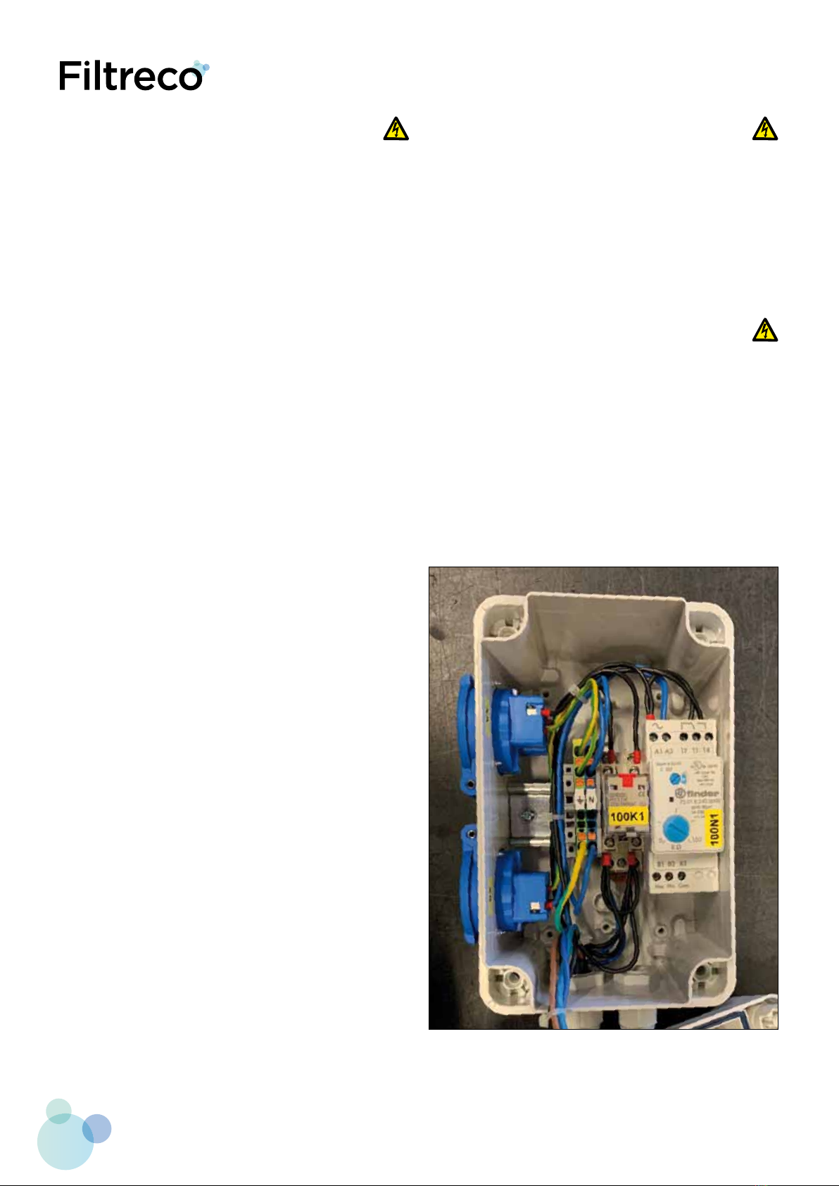
5.2 Guidelines for electrical installations
The electrical installation must be carried out in accordance
with all national legislation and may only be performed by a
nationally certified electrician. A person is considered an
electrician if they have the appropriate training, knowledge,
experience and certification, and are capable of assessing and
conducting the necessary work. The job of an electrical specialist
also includes recognising any possible hazards and complying
with all applicable regional and national standards, regulations
and provisions of law.
• For your own safety, always consult a professional electrician
in case of any problems.
• This system can only be connected to a power supply that
matches its electrical specifications. All specifications for
this system can be found in this user manual.
• The system must be protected by a residual current device
with a fixed residual current of max. 30 mA.
• Use only extension cables and power dividers that are
splash-proof and whose cable diameters are the same as
the ones supplied with the system.
• Do not allow the plug connections to come into contact
with water or moisture.
• Connect the system only to a power outlet that has been
installed according to industry standards and does not
contain a dimmer.
5.3 Safe use
• Never use this system in connection with faulty electrical
cables or a defective housing.
• Never pull on the cables to adjust the placement of the
system. Ensure that the electrical cables are not pulled
tightly.
• Lay the cables through a secure duct to avoid damage and
make sure no one can trip or fall over them.
• Only open the housing of the motor or other electrical
components if this is necessary as instructed by the user
manual.
• Only perform maintenance and other tasks on the system
as described in this user manual.
• In case of any problems that you are unable to resolve,
please contact Filtreco.
• Only use original spare parts in combination with this system.
• Do not attempt to modify the technical features or
specifications of this system in any way.
• The connector cables cannot be replaced. In case of a broken
cable, the entire system or aected part must be replaced
entirely.
• If used in the open air, a protective roof must be installed
above the control box.
• Over-voltage in the mains can cause the system to
malfunction.
• Do not inhale the spray mist from the sprayer system. The
spray mist may contain harmful bacteria.
• Once the flush cycle has completed, allow some time before
opening the cover.