Filtreco Basic combi drum 25 User manual

1www.filtreco.nl
It is
clear.
www.filtreco.nl
100287
User manual
Combi drum 25
(gravity)
EN V2-2023
ORDER NUMBER


3www.filtreco.nl
Introduction
Welcome to Filtreco: Filtration systems for koi ponds
Every koi lover knows the importance of good water quality. And that means having a good filtration
system for your pond. To keep your water clear, the choice is clear: Choose Filtreco. We know how much
you love your fish, and that is why we are the specialists that you can rely on. Your goal is to keep your
water clean, clear and healthy for your fish. But for clean water, you must choose the right filtration
system for your own specific situation. That's why Filtreco oers the widest selection of pond filters.
All with an unparalleled level of service, the lowest risk of malfunction and easy installation. Make no
mistake: when only the best quality will do, choose Filtreco. High-quality technology means quality of
life for your koi.
It is clear.
Introduction
This is the user manual for the Combi drum 25 (gravity).
By purchasing this Filtreco filter, you have made an excellent choice. Please read this user manual carefully
before you start using this system. This will enable you to familiarise yourself with the system first. Any
work carried out on or with this system must always be performed in strict accordance with this user
manual.
To ensure safe, proper use, always adhere fully with the safety guidelines. Please keep this user manual
in a safe place and transfer it to the new owner in the event that the system changes ownership.
Filtreco
Nusterweg 69
NL-6136 KT Sittard
The Netherlands
CoC 14052952
VAT NL 58.28.235.B01
Filtreco is a WTH B.V. brand.
IBAN: NL39RABO0136750729
BIC: RABONL2U
+31 46 457 25 55
info@filtreco.nl
www.filtreco.nl
V2-2023


5www.filtreco.nl
Introduction ............................................................................................................ 03
Contents ................................................................................................................... 05
1. What’s included .................................................................................................... 06
2. Product description ............................................................................................. 06
3. Assembling the filter ........................................................................................... 06
4. Instructions for use .............................................................................................. 06
5. Safety instructions ................................................................................................ 07
5.1 Danger of electrical shock in contact with water .......................................... 07
5.2 Pacemakers .......................................................................................................... 07
5.3 Guidelines for electrical installations ............................................................... 07
5.4 Safe use ................................................................................................................. 07
6. Placement and setup .......................................................................................... 08
6.1 Connecting the control box .............................................................................. 08
6.2 Connecting the electrodes and water level meter ........................................ 08
7. First use .................................................................................................................... 09
7.1 Sequence for first use ........................................................................................ 09
7.2 Adjusting water level meter ............................................................................. 09
7.3 Flush cycle ........................................................................................................... 09
8. Control box .............................................................................................................. 10
9. Control panel ........................................................................................................... 10
9.1 Various functionalities ........................................................................................ 11
9.2 Error messages .................................................................................................... 12
10. Cleaning and maintenance ................................................................................ 13
11. Troubleshooting ..................................................................................................... 14
12. Winterising ............................................................................................................... 14
13. Wear parts ................................................................................................................ 14
14. Technical specifications ...................................................................................... 14
15. Wiring and power outages ................................................................................ 14
16. Technical diagram ................................................................................................. 15
17. Diagram for assembly in a pond ..................................................................... 16
Contents
Combi
drum
filters

6Combi drum 25 (gravity)
1. What's included
• PP basin
• PP drum with brushes
• 70 micron stainless steel panel
• PP duct
• Water level meter with 3 pins
• Drum motor
• Submersible pump
• Spray tube with 4 sprayers (the first of which has a higher
flow)
• 2x 110 mm inlets
• 2x 110 mm outlets
• 2x 110 mm drum bypasses
• 2x 1 1/2" drain with ball valve
• Control box
• Cover with safety lock
• 75 L Bio wheels
• 1x air pan
2. Product description
The basis of the drum is a tank made of high-quality polypropy-
lene (PP). A PP drum with a coated mesh is incorperated in this
tank. The combi drum filter is placed gravitationally in a drain
beside the pond. The inlets are below the water surface
level, and the dirty water flows gravitationally through the floor
drains or skimmers into the first filtration chamber. On the
outflow side, the water flows through a slotted plate into the
moving bed. Because the dirty water flows through the drum,
contaminants in the water cling to the interior of the drum. As a
result, less water can flow through the mesh and the water level
on the outside of the drum sinks. The water level meter detects
this and initiates the flush cycle. This cycle consists of activating
the drum motor and spray pump. This causes the drum to turn
slightly more than one full rotation and the sprayers flush the
mesh clean. The flush water then flows into the sewage along
with the waste. The cycle repeats as often as necessary.
3. Assembling the filter
The housing of the filter consists of a PP tank with multiple
partitions. The first partition is fitted with a silicone sealing strip
at the flange which separates dirty water from clean. There are
also 2 holes in the partition which are covered with a cap. In
case of a breakdown in the drum control, the covers can be
removed to enable the water to bypass the drum and flow past
it without being filtered. This enables you to still use the biological
filtration segment of your filtration set-up. The second partition
has slotted holes that allows the water to pass into the biological
fitration chambers.
The tank is fitted with a removable waste drain. This can be
removed from the interior of the drum, which saves you the
trouble of having to disassemble the drainage line. The inclined
surface accelerates the water flow, causing the waste to be
carried along with it into the drain. There are also 4 brushes
installed on the inside of the drum which sweep away any
algae or other coarse particles that cling to the drain. The drum
filter is fitted with a removable spray tube made of PP, which
is equipped with flat jet nozzles. The sprayers feature a quick-
release system, making them easy to remove for cleaning. The
water level meter in the basin consists of 3 electrodes, 1 flush
level, 1 low-level safety and 1 common electrode. The water
level for initiating the flush cycle is adjustable. Inside the basin
is a high-pressure submersible pump which supplies water to
the sprayers under high pressure during the flush cycle.
The drum motor is installed in a water-proof compartment inside
the biological filtration section. The shaft is enclosed by a
retaining ring in the installation plate. The shaft connects to
the drum via a flange with a pipe. To remove the drum, you can
simply detach this pipe-shaft connection, after which the drum
can be taken out. You do not have to disassemble the motor to
do this. The screens can be removed by detaching the tension
straps and unscrewing the cover panel to remove it.
4. Instructions for use
The Filtreco combi drum filter and all parts and accessories
that it comes with may only be used as follows:
• for cleaning garden ponds
• according to the user manual and technical specifications
• only with water temperatures between +4 ˚C and +35 ˚C.
• only suitable for transporting water
• not for commercial or industrial purposes
• not suitable for salt water
• never use without running water
• never use in combination with chemicals, foods or
flammable/explosive liquids

7www.filtreco.nl
5. Safety instructions
This system may cause bodily harm or damage to property if
you do not use it properly and in accordance with all safety
guidelines, or if you attempt to use it for any purpose other
than that for which it was designed. This system must never be
operated by children or anyone under the age of 16, or by anyo-
ne who has a physical, mental or sensory impairment or lack of
experience and knowledge, unless they are under supervision
and have been instructed on the safe usage of the system and
informed of the dangers associated with it. Children must be
made aware that this system is not a toy. Cleaning and main-
tenance must be performed by an adult user. This must never
be performed by a child, even if they are under supervision.
5.1 Danger of electrical shock in contact with water
If your system has not been connected properly and in
accordance with the safety guidelines, and a live electrical
current comes into contact with water, this can result in electrical
shock, causing serious injury and even death. Always switch o
the current on any water-bearing equipment before you come
into contact with the water.
5.2 Pacemakers
The cover has a magnetic switch. The magnetic field may
interfere with pacemakers.
5.3 Guidelines for electrical installations
The electrical installation must be carried out in accordance
with all national legislation and may only be performed by a
nationally certified electrician. A person is considered an
electrician if they have the appropriate training, knowledge,
experience and certification, and are capable of assessing and
conducting the necessary work. The job of an electrical specialist
also includes recognising any possible hazards and complying
with all applicable regional and national standards, regulations
and provisions of law.
• For your own safety, always consult a professional electrician
in case of any problems.
• This system can only be connected to a power supply that
matches its electrical specifications. All specifications for
this system can be found in this user manual.
• The system must be protected by a residual current device
with a fixed residual current of max. 30 mA.
• Use only extension cables and power dividers that are
splash-proof and whose cable diameters are the same as
the ones supplied with the system.
• Do not allow the plug connections to come into contact
with water or moisture.
• Connect the system only to a power outlet that has been
installed according to industry standards and does not
contain a dimmer.
5.4 Safe use
• Never use this system in connection with faulty electrical
cables or a defective housing.
• Never pull on the cables to adjust the placement of the
system. Ensure that the electrical cables are not pulled
tightly.
• Lay the cables through a secure duct to avoid damage and
make sure no one can trip or fall over them.
• Only open the housing of the motor or other electrical
components if this is necessary as instructed by the user
manual.
• Only perform maintenance and other tasks on the system
as described in this user manual.
• In case of any problems that you are unable to resolve,
please contact Filtreco.
• Only use original spare parts in combination with this system.
• Do not attempt to modify the technical features or
specifications of this system in any way.
• The connector cables cannot be replaced. In case of a broken
cable, the entire system or aected part must be replaced
entirely.
• When using in the open air, a roof must be placed above
the control box and a rain-proof cover must be placed above
the motor.
• Over-voltage in the main power supply can cause the
system to malfunction.
• Do not inhale the spray mist from the sprayer system. The
spray mist may contain harmful bacteria.
• If the cover is lifted, the flush system stops working. Once
the flush cycle has completed, allow some time before
opening the cover.

8Combi drum 25 (gravity)
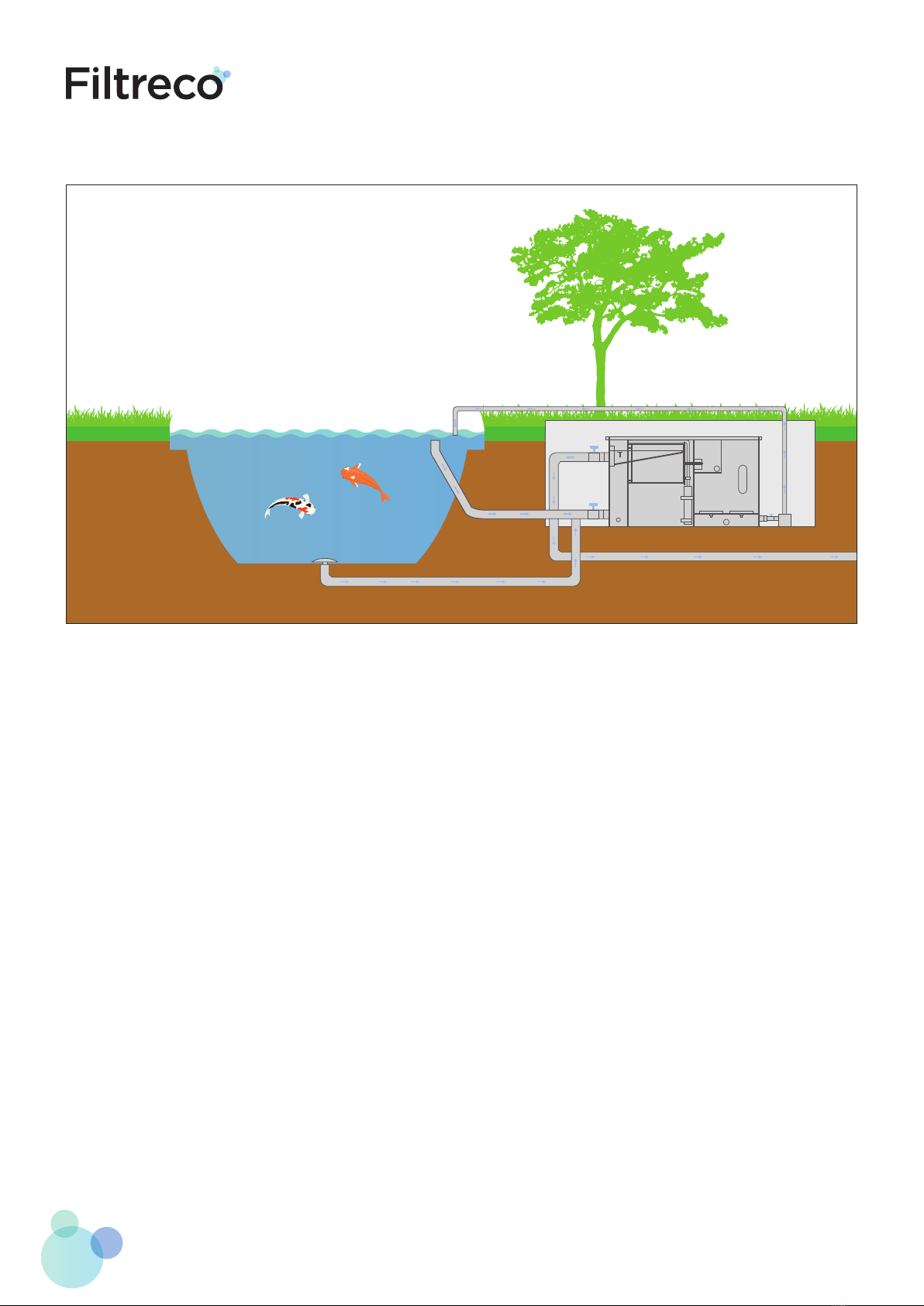
6. Placement and setup
If you plan to install this system in a way that deviates significant-
ly from the recommendations in this user manual, allow for a
specialist to inspect the installation to ensure that all technical
specifications have been met.
The combi drum filter must always be placed in a level position
on a smooth, flat subfloor. This subfloor must support the
entire bottom of the drum filter. It is recommended to place
the system on a flat cement floor. When positioning the filter,
ensure that there is adequate space on all sides so that you
have room to perform maintenance. The water level at which
the filter must be placed is indicated by an arrow in the first
filtration chamber. To ensure that the filtration system functions
properly, the water level must be kept constant and must not
deviate from the required levels. Any greater deviation will
result in an inaccurate measuring of the water level. If the
water level rises by more than 2 cm, the water will overflow via
the duct into the sewage system. To maintain a constant water
level, you can install an automatic filling station with overflow
function for your pond.
For optimal water flow, use both inlet connections. It is
recommended to use flexible rubber sleeves and joints when
connecting the water lines. These can compensate for small
dierences in dimensions and also absorb vibration.
Install slide valves or ball valves in front of and behind the filter,
so that the filter can be emptied during maintenance.
The drainage duct can be connected to a sewage connection
with a 110 mm diameter. Make sure that the duct is positioned
at an adequate incline. It is recommended to install a pipe with
a flexible rubber sleeve. These can compensate for small
differences in dimensions and also absorb vibration. They can
also be detached to remove the drainage duct.
Always use high-quality pipes with an adequate wall thickness.
Ideally, use 45 degree elbow connectors.
Lay the pipes at a downward angle so that they can be fully
emptied during the winter to protect them against frost.
Note! Electrical shock hazard. Use of this electrical system or
installation in connection with a (swimming) pond may result
in severe injury or death.
Only use this system in accordance with national and regional
regulations.
Always use suitable transport and lifting equipment when
transporting and assembling this system.
6.1 Connecting the control box
Ensure that the control box is not plugged in to the main
power supply when you open the control box!
Hang up the box on 4 screws aligned with the grooves on the
back of the box. Space between the holes in the wall: w = 280 mm
x h= 251 mm. Remember that the length of the cable for the
electrical equipment is 3 metres. Be careful when opening the
box and remember that the screws you must loosen to open
the door should not protrude when you turn the box open. The
same goes for when you close the box.
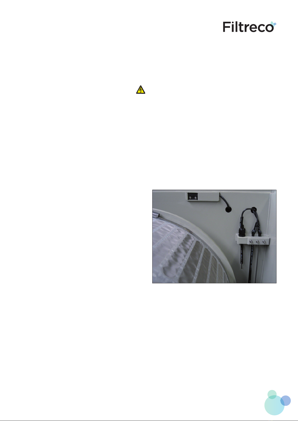
6.2 Connecting the electrodes and water level meter
Ensure that the control box is not plugged in to the main
power supply when you open the control box!
Turn the gland caps on the underside of the box and slide them
over the corresponding cable. Run the cable through the
cable gland into the box, leaving adequate length. Then twist
the gland caps closed again. Connect the electrodes as shown
below using a suitable screwdriver. The labels on the electrodes
match the codes on the connection inside the box.
9www.filtreco.nl
7. First use
Before using the combi drum filter for the first time, it is
advisable to thoroughly clean the pond manually and flush the
pipelines if possible. The reason for this is to prevent the newly
started filter from immediately experiencing an interval
breakdown.
Note! Electrical shock hazard.
• Always switch o the current to the system before coming
into contact with the pond water.
• Secure the system to prevent it from unintentionally being
switched on.
• Never connect the system to a power supply that is fitted
with a dimmer.
• Do not use the system in combination with a switch that
has a timer function.
• Only switch on the control box if the submersible pump
is below the water level and the electrodes are below the
surface.
7.1 Sequence for first use
• Remove the cover from the filter.
• Check all the water inlet and outlet connections.
• Check the line from the pump to the spray tube to ensure
it is hand-tight.
• Open the valves on the outflow side.
• Open one valve in the in-flow line.
• Switch on the pump.
• Adjust the flow of the pump to point downwards in case
the desired water level is not reached.
• Check all the water inlet and outlet connections again.
• Plug the connectors into the corresponding power sockets:
The plug for the spray pump goes into the power socket labelled
"spray pump".
The plug for the drum motor goes into the power socket labelled
"drum motor".
The plug for the water pump(s) goes into the power socket
labelled "pond pump".
Any additional components connect into the power socket
labelled "spare".
Please make sure that the power sockets can support a total
output of 2500 W from "pond pump" and "spare" combined!
7.2 Adjusting water level meter
The water level meter consists of 3 stainless steel electrodes:
• The low-level electrode: the long coated electrode
• The flush electrode: the short coated electrode
• The common electrode: the long uncoated electrode
The flush-cycle electrode is set to the lowest level by default.
This means that the flush cycle is initiated when the water level
drops by approximately 90 mm before the low level is reached.
If you would like for the flush cycle to take place sooner, you
can unscrew the cable gland and place the electrode higher.
Afterwards, tighten the cable gland again.
Note! The other two electrodes do not have an adjusting function.
7.3 Flush cycle
If the pond’s water quality is such that the time between flush
cycles lasts less than 3 minutes, then the flow into the water inlet
must be reduced to ensure that the cycle lasts for more than 3
minutes. After the contamination in the pond has decreased, the
throttling in the inlet line can be gradually reduced as long as
you allow for the flush cycle time mentioned above.

10 Combi drum 25 (gravity)
8. Control box
The control box consists of a housing with:
• 5 power sockets, namely:
- Pond pump 1 for pond pump 1
- Pond pump 2 for pond pump 2
- Spare for any extra pond pump or other electrical
equipment
Note! These 3 power sockets have a combined total output
of 2500 Watts!
- Spraypumpforthehigh-pressuresubmersiblepump-max.
1000 Watts
- Drum motor for the drum motor - max. 100 Watts
- Main switch to switch the power supply to the box on
and o
9. Control panel
The control panel is situated behind a locking hatch. It is easy
to unlock this hatch and open it upwards. Always close the
hatch carefully after every use.
You will find various buttons on the screen. Below is a brief
description of the function of these dierent buttons.
1 Buttons A/B
Use buttons Aand Bto go to the previous/next software page.
Below is the standard software page PAGE 00001.
(Standard page PAGE 00001)
2 ESC Button
By pressing the ESC button an error can be reset. If the error is
reset, but it is still present, the error code will reappear on the
screen. More detailed information about malfunctions can be
found at (p.X).
3 Buttons -/+
With buttons –and +you can change the flush times. More
detailed information about setting the flush times can be found
at (p.X).
4 OK Button
With the OK button you can perform a manual flush cycle.
Pressing this button for more than 5 seconds starts a manual
flush cycle. The currently set flush time is then executed 1x after
which it automatically returns to automatic mode.

11www.filtreco.nl
9.1 Various functionalities
1 Setting the flush timer
Depending on how dirty the water is, you can choose between
5 dierent flush times.
The normal flush time van be used for average water
contamination. If the pond is very clean and hardly contains any
contaminants, such as in the winter time, you can switch to the
‘Eco’ or ‘Smart’ setting. This reduces your water consumption.
If the water is heavily contaminated and you would like to flush
the screen more frequently, you can choose the ‘Super’ or
‘Turbo’ setting.
The nozzle only sprays 1.5 seconds after the motor starts. This
ensures that only the soiled part of the screen is sprayed. This
also prevents the screen from being sprayed in a single spot
while it is stationary.
The various flush times can be set on PAGE 00002. Go to PAGE
00002 by pressing the B key.
You can then use the + and – buttons to choose between the
following watering times:
• In Eco mode, the screen makes a quarter revolution (spray
time ± 6 seconds)
• In Smart mode the screen makes half a revolution (spray
time ± 8 seconds)
• In Normal mode, the screen makes one full revolution
(spray time ± 11 seconds)
• In Super mode, the screen makes two full revolutions
(spray time ± 22 seconds)
• In Turbo mode, the screen makes three full revolutions
(spray time ± 33 seconds)
Ensure that in between flush cycles at least 3 minutes pass. If
this time between cycles is structurally shorter, the drum will
experience a ‘cycle time alarm’.
The chosen flush time is always on display: Eco, Smart, Normal,
Super and Turbo.
(Software version page PAGE 00002)
2 Manual control
Pressing the green button (OK) for longer than 5 seconds
starts a manual rinse cycle. The currently set Flush time is then
executed 1 time after which it automatically returns to the auto
mode.
(Display during a manual rinse cycle)
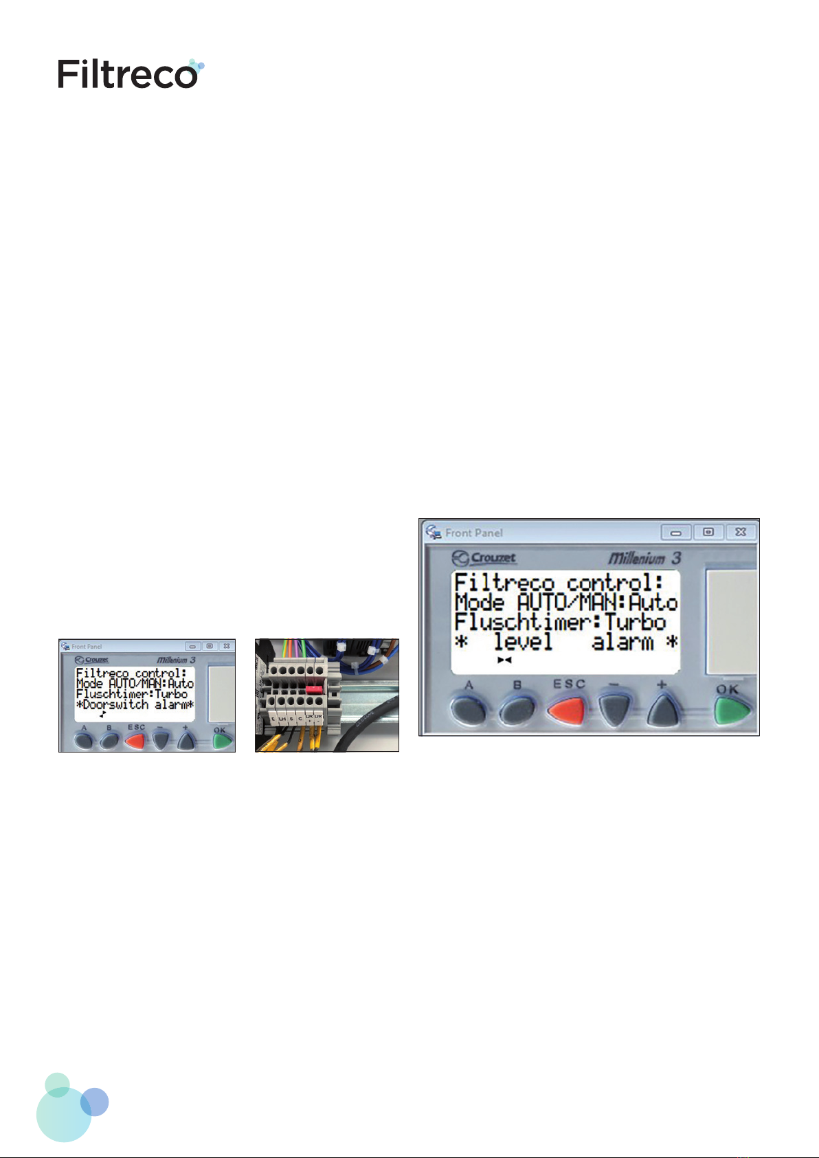
3 Adjusting the control box based on the filter arrangement
The control box of the filter can be set as either gravity or
pumped. The control box supplied with the filter is set in default
according to the delivered filter.
However, it is possible to change the setting of the control boxes
according to the selected filter arrangement. For example, the
control box can be used for a gravity filter set-up as well as for
a pumped filter set-up.
• Switch o the ‘Main switch’.
• Unplug the system form the main power supply.
• Open the control box.
• Place the wire bridge (red) on clamps 1 and 2 in case of a
gravity filter set-up. Remove the wire bridge in case of a
pumped filter arrangement.
(Wire bridge for a gravity
set-up)
On Page 0001 you can always see which software is active
for your filter. PMP refers to software for a pump-fed filter
arrangement, GRV refers to software for a gravity filter
arrangement.
(Display with software for a
gravity set-up)
12 Combi drum 25 (gravity)
9.2 Error messages
In case an error occurs, this will always be visible on the display.
The following error scan occur:
Doorswitch alarm:
The cover (contact) isn’t closed. The cover is not installed or is
not closed properly. The water pumps are switched o and no
new flush cycles will start.
• Check whether the cover is closed properly.
• Press the ESC button to reset the door switch alarm.
In case the error continues, check whether the magnet is still in
place in the holder under the cover. If so, perform the following
steps:
• Switch o the ‘Main switch’.
• Unplug the system form the main power supply.
• Open the control box.
• Check whether the DR+ and DR- cables are properly con-
nected.
In case of repeated malfunction of the door security, the
following can oer a temporary solution. It is important that a
person is always present when the filter is in operation and the
contact is bridged. Your filter will now (and temporarily) not
switch o when the lid is lifted. This can lead to a dangerous
situation as the drum continues to rotate and the spray pump
could spray with a cover that is not in place.
• Switch o the ‘Main switch’.
• Unplug the system form the main power supply.
• Open the control box.
• Place the wire bridge between DR+ en DR-.
(Display with doorswitch alarm)
Level alarm:
The water level in the filter has reached a too low level. More
water is being pumped out the filter than is going in. This fault
is indicated with level alarm. The water pumps switch o and
no rinse cycle is possible.
• Remove the cover and look for what is causing the problem.
• Check the inlets and outlets.
• In case the outer end of the flush level is under water again:
- Place the cover on the filter.
- Press the ESC button to reset the error.
• Press the OK button for at least 5 seconds. A manual flush
cycle will now begin.
- Check that the spray pump and motor are working.
- If the motor does not work, check whether the plug is
plugged in.
- If the spray pump does not work, check whether the
plug is plugged in.
- After the flush cycle is finished, the filter returns to
automatic mode.
- Remove the cover and check whether the water level
has returned to the required operating level.
- Repeat the previous steps if necessary.
- If this error message keeps recurring, increase the inflow
capacity to the filter or decrease the outflow capacity.
(Display with level alarm)
(Placed wire bridge to
bypass the door security)
13www.filtreco.nl
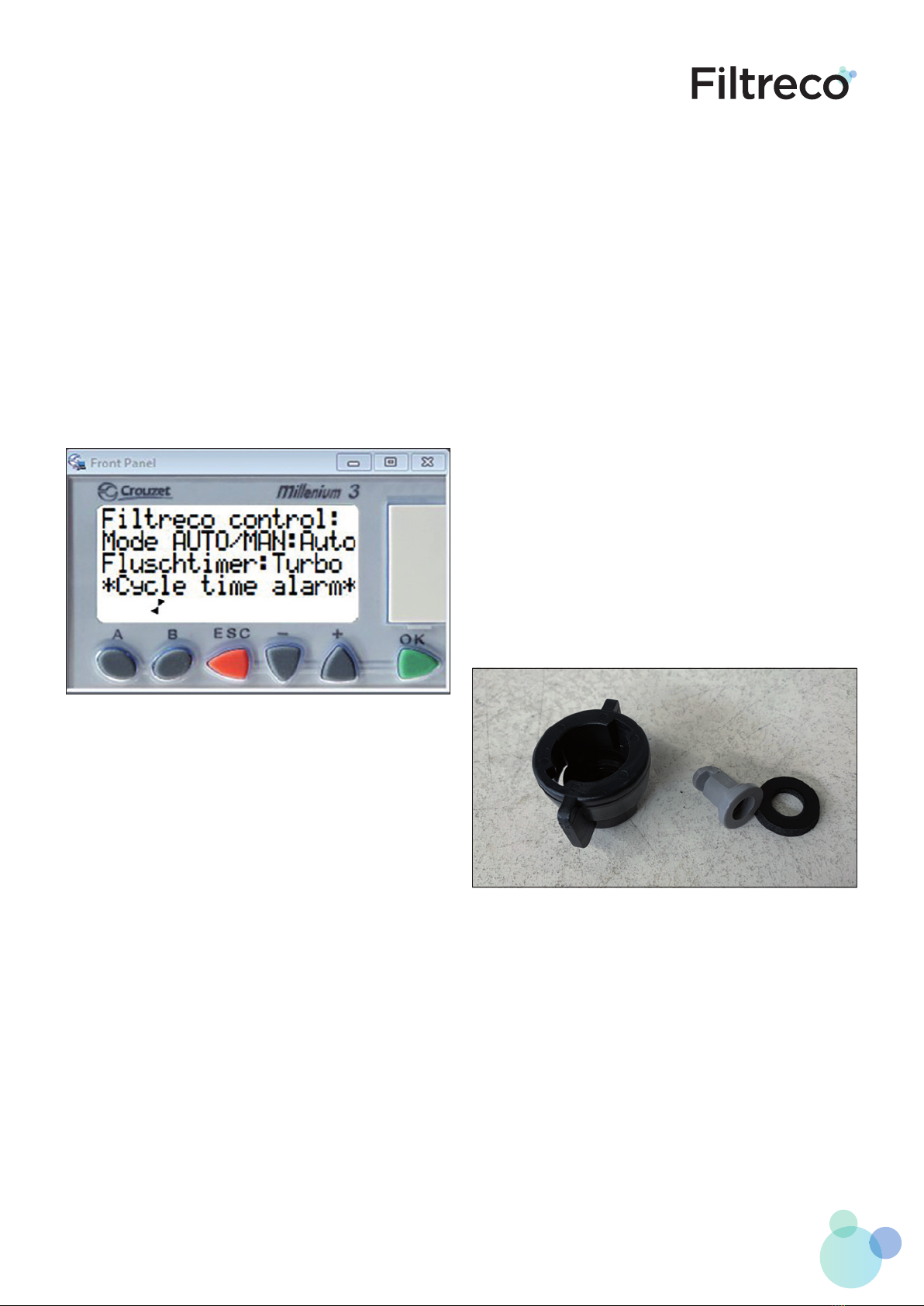
Cycle time alarm:
There have been 50 consecutive flush cycles with the interval
between these cycles being less than 3 minutes. This can occur
if the water in the pond/filter is heavily contaminated. The
water pumps are turned o.
• Set the flush electrode to the lowest level. New flush cycles
will be initiated later.
• Check the inflow pipes to see whether they are clogged.
• Check the spray heads and clean these if necessary.
Set the flush timer (temporarily) 1 or 2 levels higher to reduce
contamination.
If this does not help, reduce the outgoing flow until the worst
contamination is removed. As soon as this error message has
been resolved in the new settings, you can gradually return to
the desired setting.
(Display with cycle time alarm)
10. Cleaning and maintenance
Note! Electrical shock hazard! This can result is severe injury
or death.
When performing cleaning and maintenance, always take the
following measures:
• Always switch o the power supply and secure it from
being accidentally switched back on before you come into
contact with the water or perform any maintenance work
on the system.
• General cleaning - 1x each month:
- Switch o the "Main switch" and unplug the system from
the main power supply.
- Remove any coarse waste (such as algae) on the
inside of the drain.
- Clean the brushes inside the drum.
- Clean the inside of the drum.
- Clean the door security blocks.
- Clean the water level meter electrodes.
• Cleaning the sprayer heads - 2x per month:
- Remove the sprayer head by turning it to the left
to unscrew it from the quick-release fastener.
- Remove the gasket from the holder.
- Remove the right-angle sprayer from the connector.
- Clean it.
- Install the gasket and sprayer back into the holder.
- Turn the holder onto the clamp bracket.

14 Combi drum 25 (gravity)
• Complete cleaning:
- Switch o the "Main switch" and unplug the system from
the main power supply.
- Close the inlet and outlet spouts and drain the water
through the valve until the filter is empty.
- Remove the drain and clean it thoroughly.
- Remove the drum and brushes and clean them
under running water.
- Remove the spray pump and clean it thoroughly.
- Clean the entire inside of the filter.
• Disassemble the drum as follows:
- Disassemble the spray tube by unscrewing the
connector and removing the drain from the tube clamp.
- Disassemble the drain by loosening the bolts.
Be careful not to lose the gasket and gasket rings!
- Turn the drum until the bolt from the shaft connection
is on top. Remove this bolt.
- Slide the drum slightly towards the partition until the
tube is separated from the shaft and then carefully lift
the drum at an angle upwards out of the silicone seal. Lift
the drum out of the filter basin. Carefully set the drum
down to prevent damage to the screen.
• Assemble the drum as follows:
- Carefully lower the drum into the filter and
set its flange on the shafts of the partition.
- Press the silicone seal into the flange of the drum on
all sides, using your hand.
- Slide the drum with the flange side over the shaft.
- Turn the drum around the shaft until the hole in the shaft
is positioned underneath the hole in the tube. Reinsert
the M8 x 15 bolt and screw it tightly.
11. Troubleshooting
Error codes related to the Error LED are found in chapter 9.
The following issues may occur:
• No water flow:
- Check whether the (slide) valves are open.
- Check whether the water pumps are connected.
- Check whether the inlet or outlet is clogged.
• Insucient water flow:
- Check whether the inlet or outlet is clogged.
- There are not enough inlet connections installed.
- The circulation pump does not have enough capacity.
- There are dirty water particles on the outside of the
drum. Check the seal between the partition and the
drum.
• The high-pressure pump does not work:
- The plug is not plugged into the right power socket (spray
pump).
12. Winterising
To ensure proper functioning of the system, do not allow the
water temperature to decrease below +4 degrees Celsius.
Measures that you can take:
• Place a cover or lid over the drain.
• The control and motor cannot withstand freezing
temperatures. Be sure to place them in a location that is
protected from rain and frost.
In case water temperatures drop below +4 degrees Celsius or
there is a chance of freezing, discontinue using the system.
• Drain the system and clean it according to the instructions
• Allow the surrounding pipes to drain
• Leave the valves open
• Protect the pipes and other components from frost if
necessary.
13. Wear parts
The following parts may be subject to wear:
• Silicone drum seal Order number 100744
• Retaining ring Order number 100757
• Brush Order number 100758
• Drum screens Order number 100700
14. Technical specifications
• Operating voltage: Vac 230V
• Plug: 16 A Euro plug
• Total power output: 3680 Watts
• Cable length: 3 m
• Drum diameter: 40 cm
• Drum length: 40 cm
• Max. flow: 25 m3/h
• Weight: 85 kg
• Height above water level: 175 mm
• Min. water level: As stated
• Max. water level: As stated
• Number of panels: 1
• Number of sprayers: 4
15. Wiring and power outages
If the control box is further away than the 3-metre cable length,
use a CE-approved splash-resistant extension cable to reach
the motor and the spray pump.
The cables for the water level meter cannot be extended using
a power cable. This may cause the system to malfunction.
Original Filtreco cables can be ordered separately. Any dama-
ge to the control box caused by your own wiring or third-party
extension cables is not covered by warranty.
If following a power outage, the power circuit it reactivated, the
control box will revert to its previous mode (the mode which
was activated for longer than 10 seconds): automatic mode in
automatic mode and manual mode in manual mode. The
previously selected flush time will also be reactivated.

15www.filtreco.nl
16. Technical diagram
16 Combi drum 25 (gravity)
17. Diagram for assembly in a pond
P


18
Filtreco
Nusterweg 69
NL-6136 KT Sittard
The Netherlands
CoC 14052952
VAT NL 58.28.235.B01
+31 46 457 25 55
info@filtreco.nl
www.filtreco.nl
Filtreco is a WTH B.V. brand.
Other manuals for Basic combi drum 25
1
This manual suits for next models
1
Table of contents
Other Filtreco Water Filtration System manuals


Popular Water Filtration System manuals by other brands


CSI
CSI signature 2 hydroxr vs Installation and operation manual

UV Dynamics
UV Dynamics 8.40C Installation & operation manual

NU Aqua
NU Aqua HC-UVC1140GPD installation manual

Zodiac
Zodiac TRi Series Instructions for installation and use

EHEIM
EHEIM professionel4+ 250 operating instructions

Sterilight
Sterilight Aquasana SC200-A Installation, Operation and Maintenance Owner’s Manual