FINAL-Modellbau AEROFOAM L-39 User manual

FINAL-Modellbau In den Stöcken 20
GLOBAL JET CLUB Europe D-34305 Niedenstein
© text and photos are property of FINAL-Modellbau - All statements without guarantee.
Seite - page 1/ 7
Appendix – L-39
Ruderausschläge (standard):
Höhenruder: +/- 20mm (gemessen am Rumpf)
Querruder: +/- 15 bis 20mm (gemessen in Richtung Tip Tank)
Seitenruder: +/- 20 bis 30mm (kann individuell angepasst werden)
Landeklappen (gemessen am Rumpf):
1. Start: -25mm
2. Landung: - 65-70mm
Schwerpunkt: 115mm hinter der Nasenleiste –kann auch weiter nach hinten verlegt werden
rudder deflections:
elevator: +/- 20mm (measured on the side of fuselage)
Aileron: +/- 15-20mm (measured on the side of the wingtip)
Rudder: +/- 20-30mm (can be individually adapted)
Flap (measured on the side of the fuselage):
1. start: -25mm
2. landing: - 65-70mm
CG: 115mm behind the leading edge –can be moved to the backwards to adapt personal needs
FINAL-Modellbau In den Stöcken 20
GLOBAL JET CLUB Europe D-34305 Niedenstein
© text and photos are property of FINAL-Modellbau - All statements without guarantee.
Seite - page 2/ 7
Ergänzungen zum Zusammenbau:
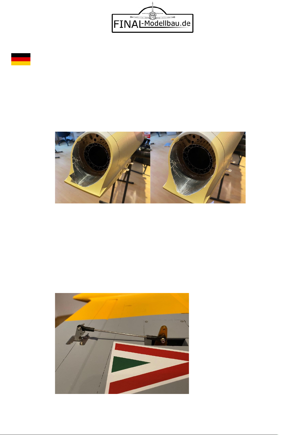
1. Turbinen starten nicht immer wir wollen, daher empfiehlt es sich oberhalb des Schubrohres
noch Aluminium-Tape als Hitzeschutz anzubringen. Dieses Tape ist in den Sets von FINAL-
Modellbau als Accessoire enthalten. Am besten benutzten sie 2x lange und 1x kürzeren
Streifen. Die beiden langen Streifen jeweils rechts und links, in der Mitte aneinander liegend.
Und den dritten kürzeren Streifen können sie dann mittig darüber kleben. Da der Rumpf hier
konisch geformt ist, kann man so alles ohne Probleme abdecken. Überreste kann man
einfach mit einem scharfen Messer abschneiden.
2. Anlenkungen:
Im Folgenden werden die Wege / Längen und Positionen der Anlenkungen der Ruder
beschrieben. Benutzt wurde eine Jeti-Anlage mit entsprechendem Empfänger, Ausschläge
der Servos können je nach Sender-System abweichen, daher dient die Einstellungen nur als
Anhalt und Empfehlung. Gerade bei Jets sind nicht viel Ruderausschläge von Nöten, daher
gilt hier immer der Grundsatz: Am Servo so nah wie möglich an den Drehpunkt und beim
Ruder immer so weit weg wie möglich !
Querruder:
Länge von Mitte Schraube zu Mitte Schraube: 88mm

FINAL-Modellbau In den Stöcken 20
GLOBAL JET CLUB Europe D-34305 Niedenstein
© text and photos are property of FINAL-Modellbau - All statements without guarantee.
Seite - page 3/ 7
Höhenruder:
Länge von Mitte Schraube zu Mitte Schraube: 97mm
Seitenruder:
Länge von Mitte Schraube zu Mitte Schraube: 95mm

FINAL-Modellbau In den Stöcken 20
GLOBAL JET CLUB Europe D-34305 Niedenstein
© text and photos are property of FINAL-Modellbau - All statements without guarantee.
Seite - page 4/ 7
Landeklappen:
Länge von Mitte Schraube zu Mitte Schraube: 79mm
3. Fahrwerk:
In den Zylinder des Fahrwerks ist ein klebendes Fett enthalten, um eine maximale Dämpfung
zu erzielen, dies verhindert effektiv ein Springen des Models beim Landen. Gerade auf
Rasenplätzen und nach individuellen Vorlieben kann man dieses Fett teilweise oder komplett
entfernen, das Fahrwerk wird dadurch softer und federt leichter, ‚springt‘ aber wieder
leichter aus den Federn. Je nach Geschmack kann man dies über die Entnahme dieses Fettes
oder durch zusätzliches Schmieren zum Beispiel mit Silikonöl einstellen.
additions to the assembly:
1. Turbines do not always start as we want them to do, so it is advisable to apply aluminum
tape above the thrust pipe as heat protection. This tape is included in the sets from FINAL-
Modellbau as an accessory. It is best to use 2x long and 1x shorter strips. Apply the two long
stripes on the right and left, connecting with the end in the middle. Then apply the third
shorter strip in the middle. Since the hull is conical here, everything can be covered without

FINAL-Modellbau In den Stöcken 20
GLOBAL JET CLUB Europe D-34305 Niedenstein
© text and photos are property of FINAL-Modellbau - All statements without guarantee.
Seite - page 5/ 7
any problems. You can simply cut off any remains with a sharp knife.
2. Push rods /linkages:
The ways / lengths and positions of the linkages of the rudders are described below. A Jeti
system with the appropriate receiver was used, deflections of the servos may vary depending
on the transmitter system, so the settings only serve as a guide and recommendation. With
jets in particular rudder deflections are very small, which is why the following principle
always applies: on the servo as close as possible to the pivot point and on the side of the
rudder apply always as far away from the pivot point as possible !
Ailerons:
Length from center screw to center screw: 88mm

FINAL-Modellbau In den Stöcken 20
GLOBAL JET CLUB Europe D-34305 Niedenstein
© text and photos are property of FINAL-Modellbau - All statements without guarantee.
Seite - page 6/ 7
Elevator:
Length from center screw to center screw: 97mm
Rudder:
Length from center screw to center screw: 95mm

FINAL-Modellbau In den Stöcken 20
GLOBAL JET CLUB Europe D-34305 Niedenstein
© text and photos are property of FINAL-Modellbau - All statements without guarantee.
Seite - page 7/ 7
Flaps:
Length from center screw to center screw: 79mm
3. Landing gear struts:
An adhesive grease is contained in the cylinder of the landing gear to achieve maximum
damping, this effectively prevents the model from jumping when landing. Especially on grass
runways and according to individual preferences, you can remove some or all of this grease,
which makes the landing gear softer and bounces more easily, but 'bounces' back out of the
springs more easily. Depending on your taste, this can be set by removing this grease or by
additional lubrication, for example with silicone oil.
Table of contents
Popular Toy manuals by other brands


Fisher-Price
Fisher-Price V8601 instruction sheet

Tamjets
Tamjets A4 Skyhawk Assembly and Flight Set-up Manual

LEGO
LEGO 70800 Assembly instruction

M.T.H.
M.T.H. USRA 0-8-0Steam Locomotive Operator's manual

Educational Insights
Educational Insights Laser Line Maker manual

MTHTrains
MTHTrains 20-5524-1 Operator's manual

Little Tikes
Little Tikes COZY TRUCK 642319M Assembly instructions

Lionel
Lionel Conventional 2-6-0 Mogul Steam Locomotive owner's manual

Tabletop Scenics
Tabletop Scenics TT COMBAT TTSC-SFU-103 instruction manual

LEGO
LEGO 76055 Assembly information

PIKO
PIKO BR S 499 Instructions for use

Canon
Canon Creative Park Kissing Dolls Assembly instructions