manuals.online logo
Brands
  1. Home
  2. •
  3. Brands
  4. •
  5. Phoenix Model
  6. •
  7. Toy
  8. •
  9. Phoenix Model Pepperpot User manual

Phoenix Model Pepperpot User manual

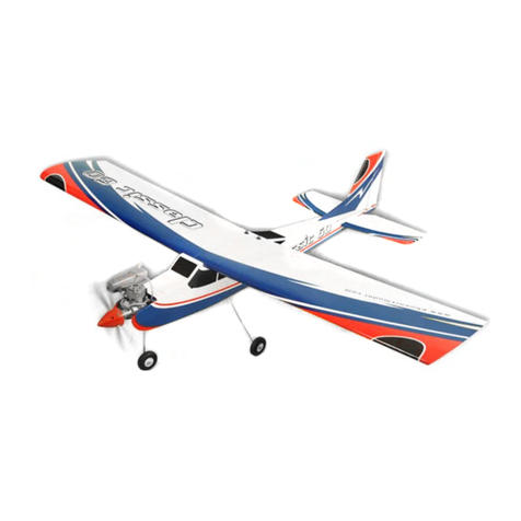
Pepperpot
49in Span Electric Sports Model 4/500w Motors & 4-6 Channel RC Equipment.
Designed by: Stan Yeo Produced by: Phoenix Model Products
Introduction
The Pepperpot is a 4/5 channel stylish
electric power sports aerobatic model that
has a spritely performance. With a typical
4/500w 3542 1250Kv motor and using 3S
22/2700mA LiPos the Pepperpot. it is both a
delight to fly and build. It will attract
complements on both fronts. The all wood
easy build construction follows the now well
proven path of other models in our range in
that it incorporates a fully sheeted built-up
wing with a selection of cut parts and
accessories. The optional flaps are an
added bonus for those who like to play with
different control setups
Radio Equipment Required
The recommended radio equipment
required for the Pepperpot is two metal
geared micro servos i.e. Hitec HS82MG or
the Ripmax New Power XL16HM or
XL17HMB for the Ailerons/Flaps plus two
standard size servos for the Rudder &
Elevator with a 4/6 channel receiver. For
Flapperon operation a 6ch transmitter and
6ch receiver is required.
Electrical Power Train
The Pepperpot requires a 3536/42
Brushless Motor rated at 400-500w and
1000 – 1300 Kv. A 50/60A Speed Controller
(ESC) and a 2200 3S LiPo. The prototype
used a 3542 1250Kv motor with a 60A ESC.
9x6in APCE propeller and a 2200mAhr 3S
30C LiPo. With this set-up the Pepperpot is
more than adequately powered with typically
flight duration of up to10 minutes. If you use
a different specification motor or a 4S
battery then a different size propeller should
be used and be aware this could have an
impact on the balance point. If you are
unfamiliar with model electrics then please
read the articles on our website
www.phoenixmp.com .
Tools / Materials Required
The tools required to build the Pepperpot
are a modelling knife with spare blades, a
2ft /1 Metre Straight Edge, a miniature David
Plane, 180 grade Wet & Dry sanding block
and soldering iron. The glues used to build
the model are white PVA wood glue, thin
Superglue (please observe safety
precautions) and a very small quantity of
two part epoxy. We recommend using a
polyester heat shrink film for covering such
as Oracover/Profilm or the thinner more
economic version Easycoat.
Please Note: PVA is the recommended glue
for nearly ALL wood joints, particularly when
building the wing. Also for maximum glue
joint strength we recommend lightly sanding
laser cut edges before gluing.
Building the Fuselage
1. Lightly sand the ply fuselage doublers
with 180 grade wet and dry to remove
the 'release' agent. Remove dust with a
small brush or vacuum cleaner.
2. Using a spirit based contact adhesive
such as Uhu or EvoStik glue the ply
nose doublers in position ensuring there
is a left and right side. Motor side thrust
and down thrust is built in consequently
the right side is shorter than the left!!!
3. Mark out the position of formers F2, F3
and F4 on the inside of the fuselage
sides ensuring there is a left and right
side (they are marked!).
4. Cut slot for Rudder and Elevator cable
exits as indicated on plan (Both
underneath Tailplane).
5. Lightly sand edges of fuselage side to
prepare gluing surface to receive top
and bottom sheet.
6. Glue strip longeron super structure
including wingseat doubler, spruce tail
doubler and 4.5mm x 12mm coaming
support strip.
7. Glue F2A to F2.
8. Using F2 & F4, join fuselage sides
together over the plan ensuring that it is
both are straight and square.
9. Fit F2 and 3mm cockpit floor. Use
masking tape to ‘pull’ fuselage sides in
for snug fit.
10. Glue Fin to Tailplane ensuring it is
central and vertical.
11. Fit ‘oversize’ 1.5mm sheet coaming
sides. Use masking tape to hold in
position whilst the glue sets.
12. Using 180 grade Wet & Dry sand 1.5mm
coaming sheet flat to receive top
coaming. Note coaming sheet taper
ends at leading edge of the Tailplane.
13. Taper underside of rear of top coaming.
To align coaming sheeting and top of
Tailplane use plan and dry fitting
Tailplane.
14. Sand top coaming to shape.
15. Fit Rudder and Elevator control rods.
Control rods exit fuselage on opposite
sides. Anchor to fuselage sides every
100-120mm using scrap balsa.
Superglue in place. Before fixing control
cables check control cables are not
binding and move freely. Tie and glue
control rods together where they cross.
16.
17. Assemble wing retaining bolt plate and
glue tapered spruce support plates to
fuselage sides.
18. Fit wing to
fuselage and
drill holes for
dowel tubes in
wing using a
long shank
5mm drill bit or one fashioned from 4mm
piano wire.
19. Glue 6mm ply undercarriage plate in
position.
20. Using undercarriage to assist alignment
glue 6mm ply U/C Torsion plates in
position.
21. Fit Fuselage bottom front and back
including ply undercarriage plate using
PVA glue.
22. Bend 2mm piano
wire tailskid to
shape and fit
tailskid
assembly.
23. Fit 4mm ply
motor mount. If
using a 3542 motor then set the mount
back 3mm from front of fuselage sides.
Glue 3mm sq. around front of mount. If
using a 3536 motor mount motor flush
with end of
fuselage
sides.
24. Glue 6mm
triangular
reinforcing
strip around
rear of motor
and base of
U/C torsion
plates
25. Fit fuselage top front and rear of the
Hatch and fit 0.8mm ply end plates.
26. Construct
Hatch and fit
as per
diagram.
27. Glue
Tailplane in
place checking that it is both horizontal
and the distances between hinge
corners on tailplane to rear corner of
cockpit are equal.
28. Fit Rudder and Elevator servos.
29. Cut Mylar Hinges to size (12mm x
25mm). Trim corners to stop them
digging in and roughen gluing surface
with Wet & Dry.
30. Hinge Rudder and Elevator control
surfaces. Do NOT glue until the model is
covered.
Building the Wings
1. To protect the plan cover in either thin
polythene or cling film.
2. Join front & back 1.5mm sheeting. Use
metal straight edge to trim for a good
joint. The sheeting has been Laser cut
but may require further trimming due
moisture changes in the wood. Sellotape
them together along the joint. Hinge joint
back and insert PVA glue. Place on flat
surface and wipe away excess glue.
Run Sellotape along top of joint. Weight
down until glue set. Repeat for other
three pieces.
3. Accurately align bottom sheet on plan
and pin to plan. Note: 1.5mm sheeting
overhangs the front and rear of the wing
ribs by approximately 2mm.
4. Accurately mark position of mainspar on
bottom sheet and using a straight edge
set square glue and pin mainspar in
place.
5. Elevate underside of sheeting at front
and rear
with
scrap to
conform
with
airfoil
profile.
6. Omitting W1 glue wing ribs in position.
7. Glue 6mm strip to front of Mainspar
1mm from the top. Ensure that it is a
snug fit between the ribs.
8. Glue together Wing Servo Mount
Assembly using PVA and before glue
sets fit mount into servo bay between
W4&5. Consult plan as they are handed
i.e. there is a left and right hand! Push
sides of servo mounts against W4&5 to
make good gluing contact.
9. Using guide lines on plan glue ribs in
place. For the servo bay ribs use servo
mount for alignment.
10. Build second Wing.
11. Trim and align root end of each wing
panel. Note the mainspars are straight
and not swept in either direction. Glue
panels together with 10mm dihedral
under each tip.
12. Glue 0.8mm ply servo lead exit support
washers in place and 1.5mm ply wing
braces.
13. Fit W1 & sub-ribs.
14. Thread a string through servo bay and
ribs to aid final servo installation.
15. Fit 1.5mm top sheeting taking care to
ensure that it is making contact with both
the wing ribs and the mainspar. Tip: Use
masking tape to help support sheeting
whilst glue sets.
16. Plane / sand wing sheeting back to ends
of ribs using David Plane and large flat
180 grade Wet & Dry sanding block.
17. Place Sellotape along sheeting edges to
collect surplus glue. Tip: Do not try to
align Sellotape with edge of sheet but let
it overlap and trim with a sharp scalpel.
18. Using PVA glue fit leading edge and rear
spar using masking tape to hold in
position whilst glue sets.
19. When glue is set remove Sellotape.
20. Carefully plane/sand both rear spar and
leading edge to shape. Tip: when using
David Plane set blade at slight angle so
that the cut is thinner on one side of the
plane. It helps control thickness of cut.
21. Glue 0.8mm ply end ribs to balsa tips.
Again there is a Left & Right! Roughly
shape and glue tip in place taking care
to align tip end rib with wing end rib.
22. Sand wing tips to shape.
23. Fit centre section trailing edge.
24. Shape Ailerons and cut to length. At this
stage do not make allowance for 0.8mm
ply ends.
25. Tape ailerons in position using Wing Tip
as a reference. Check for twist.
26. Using ailerons as a guide mark TE
position on centre section trailing edge.
Lightly draw guide line along TE.
27. Shape centre section trailing edge using
Aileron as a reference.
28. Drill holes for brass wing dowel
29. Mark position of aileron control horn.
Draw a line on underside of Ailerons to
indicate extent of shaping required for
down going Aileron relief. Shape
ailerons and cut to length allowing
clearance for 0.8mm ply end plates and
covering material.
30. When complete add 0.8mm ply end
plates using Superglue to both Ailerons
and Centre Section.
31. Cut slot for aileron control horn. Needs
to snug fit. Roughen surface and
superglue in position AFTER covering.
32. Give wing a final sand using 320 grade
Wet & Dry.
Covering & Finishing
1. The originals were covered in heat
shrink film (Profilm/Oracover). This has
proved more than adequate. Should you
wish to cover in a different material
please take into account any potential
weight penalty that it may incur and
puncture / tear resistance / repairability.
2. Give the complete model a final sanding
with 320 grade Wet & dry. DO NOT use
a sanding block on wing sheeting. It
thins the sheeting on top of the rib and
seriously weakens the wing.
3. Before covering vacuum clean the
model to remove embedded dust to
avoid ‘pimpling’ when covering.
4. Please follow the instruction for the
covering material being used. Normal
procedure is to tack the material at one
end. Tack the other end and then
proceed to gently stretch and tack along
its length before sealing all along the
edges and shrinking with a Heat Gun.
5. Spray motor cowl to match your colour
scheme (rattle can) (Hycote gloss white
is a perfect match for white Profilm).
6. Fit motor using M3 x 12mm countersunk
screws.
7. Fit motor cowl using clear UV resistant
tape and fit propeller.
8. Fit aileron servo output arms in centre
position.
9. Superglue Aileron control horns in
position and hinge Ailerons Sellotape
Diamond or substitute or Oracover.
10. Centre Aileron servos using transmitter
sub-trim and adjust Aileron pushrods.
When satisfied tape servo covers in
place.
11. Fit controls,
hinge
rudder,
carry out
final
adjustment
to elevator neutral and balance the
model including the wings (laterally).
12. Set the control movements as per the
plan i.e. Elevator +/- 10mm. Rudder +/-
30mm. Aileron Up 16mm Down 13mm.
Full up Elevator, Landing Flap1 Down
6mm Landing Flap2 Down 12mm.
Balance point 65mm +/- 5mm from
Leading Edge. Exponential is
recommended for both Aileron and
Elevator controls. Typically 30%.
Landing flap may require elevator
compensation to counteract any pitch
change when deployed. It is
recommended that a pitch change check
is carried out at a safe height!!
13. If using 2.4Ghz R/C equipment it is
recommended that you re-bind / pair the
receiver to update failsafe settings after
set-up and before flying your Pepperpot.
Remember that the throttle control must
be in the LOW throttle position when
binding / paring. Failure to do this has
resulted in a number of serious
accidents in the past. Remember the
Transmitter is first ON and last OFF!
14. Check that when the transmitter is
turned off that motor STOPS.
15. A few simple rules for electrics. In flight it
is normal for the battery / speed
controller (ESC) to get warm but if it gets
hot then the reasons could be
insufficient cooling, too large a propeller
or the battery / ESC of too low a
specification. For the battery it could be
due poor condition, too low a ‘C’ rating
allied to lack of capacity. To avoid
discharging the battery below the
recommended voltage always land when
you notice there is less power on full
throttle. When landing in foliage cut the
throttle immediately to avoid burning out
the speed controller.
Trimming
Trimming is carried out in two stages. The
first stage is to set up the power OFF glide
by adjusting the balance point as required
by moving the battery backwards and
forwards. The second stage is to fine tune
the thrust line of the motor by inserting
washers, as appropriate, between the motor
star plate and the motor mount. To test for
sidethrust put the model in steep climb, into
wind, and note if the model turns to the right
or left as the speed falls off and place
washers as before on the side the model is
turning towards. Downthrust is determined
by the amount of elevator required to
maintain the power on flight path desired.
Some modellers will want the model to go
into a steady climb under power whilst
others may prefer the model to remain in
level flight. Adjust motor Downthrust using
washers as before. Mixing a small amount
down elevator with the throttle can be used
to fine power on flight.
Flying
When satisfied the model is set-up and
ready to go choose a suitable site and day
to test fly it i.e. wind not too strong or
turbulent. If you are inexperienced please
seek assistance for the maiden flight. If set
up correctly very little trimming should be
required. The Pepperpot, as previously
mentioned, is a very lively model and if set
up with extravagant control throws is
capable of almost any manoeuvre that could
be expected of this type of model including
sustained inverted flight, inside and out side
loops plus blink and miss rolls. The only real
limitation is your flying ability and
imagination!
Happy landings,
Stan
13 Jun. 16

Other Phoenix Model Toy manuals

Phoenix Model DECATHLON MK2 User manual

Phoenix Model

Phoenix Model DECATHLON MK2 User manual

Phoenix Model Spitfire User manual

Phoenix Model

Phoenix Model Spitfire User manual

Phoenix Model Tiger Moth User manual

Phoenix Model

Phoenix Model Tiger Moth User manual

Phoenix Model Tiger Moth User manual

Phoenix Model

Phoenix Model Tiger Moth User manual

Phoenix Model Thunderbolt P47 User manual

Phoenix Model

Phoenix Model Thunderbolt P47 User manual

Phoenix Model WACO F5C User manual

Phoenix Model

Phoenix Model WACO F5C User manual

Phoenix Model BERGFALKE User manual

Phoenix Model

Phoenix Model BERGFALKE User manual

Phoenix Model TUCANO 60CC User manual

Phoenix Model

Phoenix Model TUCANO 60CC User manual

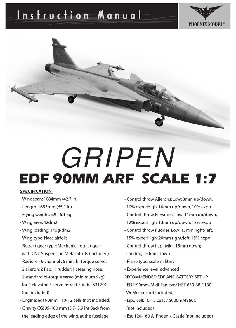
Phoenix Model GRIPEN User manual

Phoenix Model

Phoenix Model GRIPEN User manual

Phoenix Model Tucano Electric User manual

Phoenix Model

Phoenix Model Tucano Electric User manual

Phoenix Model Classic User manual

Phoenix Model

Phoenix Model Classic User manual

Phoenix Model Cap 232 User manual

Phoenix Model

Phoenix Model Cap 232 User manual

Phoenix Model Stinson Reliant User manual

Phoenix Model

Phoenix Model Stinson Reliant User manual

Phoenix Model YAK54 YAKOVLEV User manual

Phoenix Model

Phoenix Model YAK54 YAKOVLEV User manual

Phoenix Model Preceptor ARF EDF 90mm User manual

Phoenix Model

Phoenix Model Preceptor ARF EDF 90mm User manual

Phoenix Model Tiger 3 User manual

Phoenix Model

Phoenix Model Tiger 3 User manual

Phoenix Model Cariba Mk2 User manual

Phoenix Model

Phoenix Model Cariba Mk2 User manual

Phoenix Model decathlon User manual

Phoenix Model

Phoenix Model decathlon User manual

Phoenix Model KATANA-61 User manual

Phoenix Model

Phoenix Model KATANA-61 User manual

Phoenix Model super constellation User manual

Phoenix Model

Phoenix Model super constellation User manual

Phoenix Model MUSTANG P51 - EP User manual

Phoenix Model

Phoenix Model MUSTANG P51 - EP User manual

Phoenix Model Sonic High Wing User manual

Phoenix Model

Phoenix Model Sonic High Wing User manual

Phoenix Model LASER User manual

Phoenix Model

Phoenix Model LASER User manual

Phoenix Model BAE HAWK User manual

Phoenix Model

Phoenix Model BAE HAWK User manual

Popular Toy manuals by other brands

Faller ABBY CHURCH instructions

Faller

Faller ABBY CHURCH instructions

LEGO Excavator manual

LEGO

LEGO Excavator manual

Eduard 73 744 Assembly instruction

Eduard

Eduard 73 744 Assembly instruction

Vollmer 43541 Mounting instruction

Vollmer

Vollmer 43541 Mounting instruction

Topcom LILY user guide

Topcom

Topcom LILY user guide

Horizon Hobby E-flite Twin Otter 1.2m instruction manual

Horizon Hobby

Horizon Hobby E-flite Twin Otter 1.2m instruction manual

VINCI VINCI Tab Technical guide and user manual

VINCI

VINCI VINCI Tab Technical guide and user manual

Learning Resources Mini Muffin Match Up quick start guide

Learning Resources

Learning Resources Mini Muffin Match Up quick start guide

Hasbro Baby Alive Sip 'n Slurp 18689 instruction manual

Hasbro

Hasbro Baby Alive Sip 'n Slurp 18689 instruction manual

ATOMIC MASS GAMES Star Wars Legion Assassin Droid SWL99 quick start guide

ATOMIC MASS GAMES

ATOMIC MASS GAMES Star Wars Legion Assassin Droid SWL99 quick start guide

Bresser Junior 96-60130 instruction manual

Bresser Junior

Bresser Junior 96-60130 instruction manual

Eduard Sea Harrier FRS1 S.A. quick start guide

Eduard

Eduard Sea Harrier FRS1 S.A. quick start guide

Kolcraft 1-2-3 Ready-to-Grow Assembly and use instructions

Kolcraft

Kolcraft 1-2-3 Ready-to-Grow Assembly and use instructions

Fisher-Price CFN02 instructions

Fisher-Price

Fisher-Price CFN02 instructions

Mattel Barbie W3153 instructions

Mattel

Mattel Barbie W3153 instructions

Super Flying Model P-51D Mustang instruction manual

Super Flying Model

Super Flying Model P-51D Mustang instruction manual

Smoby Easy Biscuits Factory quick start guide

Smoby

Smoby Easy Biscuits Factory quick start guide

Lionel Girl's Set owner's manual

Lionel

Lionel Girl's Set owner's manual

manuals.online logo
manuals.online logoBrands
  • About & Mission
  • Contact us
  • Privacy Policy
  • Terms and Conditions

Copyright 2025 Manuals.Online. All Rights Reserved.