Fineco Electric PM835 User manual
User Manual PM835
Document code: Fineco835-1-1.1 Revision2.001
Shanghai fangqiu electric CO.,LTD. www.fangqiu.com.cn Email: antsmw@163.com
User Manual
Revision 2.001
English
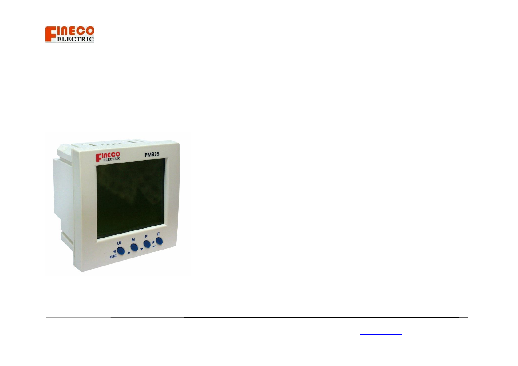
Power quality meter
PM835
Shanghai fangqiu electric Co.,LTD.
Benefits and Main Features
● DIN 96×96 Standard Format
● True-RMS Measuring Parameter
▲ Current(per phase,residual,3 phase
▲ Voltage(L-L,L-N,3-Phase)
▲ Active power(per phase,3-Phase)
▲ Reactive power(per phase,3-Phase)
▲ Apparent Power(per phase,3-Phase)
▲ Power Factor(per phase,3-Phase)
▲ Frequency
● Energy Readings
▲ Import active energy, export active energy ,total active energy
▲ Import reactive energy, export reactive energy ,total reactive energy
▲ Apparent energy
● Demand Reading
▲ Demand Current (per phase present, peak,3 phase)
▲ Demand Voltage(per phase present, peak)
▲ Demand active power(3 phase present, peak,)
▲ Demand reactive power(3 phase present, peak,)
● Power Analysis
▲ Phase/wire Voltage THD, odd/even THD
▲ Phase/wire Voltage 2nd-----60th Harmonic
▲ Current THD, odd/even THD
▲ Current 2nd-----60th Harmonic
▲ Voltage/current unbalanced

User Manual PM835
Document code: Fineco835-1-1.1 Revision2.001
Shanghai fangqiu electric CO.,LTD. www.fangqiu.com.cn Email: antsmw@163.com
▲ Voltage/current sequence component
● Digital input /output
▲ 2 independent digital inputs. Use as pulse accumulators or Digital inputs
▲ 2 independent digital outputs. Use as Modbus controlled outputs or Alam
output.
● Communication
▲ RS485port
▲ Baud rate: 1200bps~115200bps
▲ Modbus-RTU protocol
Index:
1. Safety instruction
1.1 Information for Your Own Safety
1.2 Qualified personnel
1.3 Use for the intended purpose
1.4 Proper handling
2. Technical description
2.1 Voltage Inputs
2.2 Current Inputs
2.3 Isolation
2.4 Environmental Rating
2.5 Sensing Method
2.6 Update Rate
2.7 Power Supply
2.8 Communication Format
2.9 KYZ Pulse
3.Dimensions

User Manual PM835
Document code: Fineco835-1-1.1 Revision2.001
Shanghai fangqiu electric CO.,LTD. www.fangqiu.com.cn Email: antsmw@163.com
4.Wiring diagrams
5. Display parameter
5.1 Phase volts, line volts, phase amps
5.2 System power factor, frequency, phase power factor, volts
THD ,amps THD
5.3 Phase watts, phase var, phase VA , system power
5.4 kWh /kvarh energy
5.5 Time-average volts, Time-average amps, Peak time-average
volts, Peak time-average amps, Peak hold phase volts, Peak hold
phase amps
5.6 Max system power factor and Max frequency, Min system
power factor And Min frequency, Volts Sequence component,
Amps sequence component
5.7 Power system demand, Min MD, Peak hold MD, Min system
power, Max system power
6. Setting parameter
6.1 Set relays status (parameter 0)
6.2 Set Modbus ID (parameter 1)
6.3 Set RS-485 Baud Rate
6.4 Set PT , CT
6.5 Set backlight time
6.6 Set auto display time interval
6.7 Clear energy kWh/kvarh
6.8 Set password
6.9 Panel meter information
6.10 Individual Harmonic
6.11 Set System connect status
6.12 Set volts, amps, power period
7. Technical support
User Manual PM835
Document code: Fineco835-1-1.1 Revision2.001
Shanghai fangqiu electric CO.,LTD. www.fangqiu.com.cn Email: antsmw@163.com
1. Safety Instruction
1.1 Information for Your Own Safety
This manual does not contain all of the safety measures for operation of
this equipment (module, device) because special operating conditions,
local code requirements or local regulations may necessitate further
measures. However, it does contain information which must be adhered to
for your own personal safety and to avoid damage to the equipment. This
information is highlighted by a warning triangle with an exclamation mark
or a lightning bolt depending on the severity of the warning.
Warning
Means that failure to observe the instruction can
result in death, serious injury or considerable material
damage.
Caution
Means hazard of electric shock and failure to take the
necessary safety precautions will result in death,
serious injury or considerable material damage.
1.2 Qualified personnel
Installation and operation of this equipment described in this manual may only
be performed by qualified personnel.
Only people that are authorized to install, connect and use this equipment and
have the proper knowledge about labeling and grounding electrical equipment
and circuits and can do so according to safety and regulatory standards are
considered qualified personnel in the manual.
1.3 Use for the intended purpose
The equipment (device, module) may only be used for the application cases
specified in the catalog and the user manual and only in connection with
devices and components recommended and approved by Finco Electric.
1.4 Proper handling
The prerequisites for perfect, reliable operation of the product are proper
transport, storage, installation and connection, as well as proper operation and
maintenance. When operating electrical equipment, certain parts of this
equipment carry dangerous voltages. Improper handling can therefore result in
serious injury or material damage.
Only use isolated tools suitable for the voltages the meter is used for.
Do not connect while circuit is live (hot).
Place the meter only in dry surroundings.
Do not mount the meter in an explosive area or exposed to dust,
mildew and/or insects.
Make sure the used wires are suitable for the maximum current of
this meter.
Make sure the AC wires are connected correctly before activating the
current/voltage to the meter.
Do not touch the meter’s connection clamps directly with your bare
hands, with metal, blank wire or other conducting material as that
will cause an electric shock and possibly cause injury.
Make sure the protection cover is placed after installation.

User Manual PM835
Document code: Fineco835-1-1.1 Revision2.001
Shanghai fangqiu electric CO.,LTD. www.fangqiu.com.cn Email: antsmw@163.com
Installation, maintenance and repair should only be done by qualified
personnel.
Never break the seals to open the front cover as this might influence
the functionality or accuracy of the meter, and will void all warranty.
Do not drop, or allow physical impact to the meter as there are high
precision components inside that may break and render the meter
measurement inaccurate.
2. Technical description
2.1 Voltage Inputs
• 20-280 Volts Line To Neutral, 20-480 Volts Line to Line
• Universal Voltage Input
• Input Withstand Capability – Meets IEEE C37.90.1 (Surge Withstand
Capability)
• Programmable Voltage Range to Any PT ratio
• Supports: 3 phase 3 or 4 wires, 400/230V, 110/63V,208/120V
• Burden: 0.36VA per phase Max at 600V, 0.014VA at 120 Volts
• Input wire gauge max (AWG 12 / 2.5mm2)
2.2 Current Inputs
• Class : (0 to 5) A, 5 Amp Nominal
• Fault Current Withstand: 100 Amps for 10 Seconds, 300 Amps for 3 Seconds,
500 Amps for 1 Second.
• Programmable Current to Any CT Ratio
• Burden 0.005VA per phase Max at 11Amps
• 5mA Pickup Current
• Pass through wire gauge dimension: 0.177" / 4.5mm
• Continuous current withstand: 20 amps for screw terminated or pass through
current connections
2.3 Isolation
All Inputs and Outputs are galvanic ally isolated to 2500 Volts AC.
2.4 Environmental Rating
Storage: (-25 to +70)° C
Operating: (-10 to +65)° C
Humidity: to 75% RH Non-Condensing
Faceplate Rating: NEMA12 (Water Resistant)
Environment : IP54 standard, IP65 optional
Mounting Gasket Included
2.5 Sensing Method
• RMS
• Sampling at 120+ Samples per Cycle on all channels measured readings
simultaneously
• Harmonic %THD (% of Total Harmonic Distortion)
2.6 Update Rate
• Watts, VAr and VA-100msec
• All other parameters-1second
2.7 Power Supply
Option D2:
• (65 to 275) Volts AC and (90 to 380) Volts DC. Universal AC/DC Supply
User Manual PM835
Document code: Fineco835-1-1.1 Revision2.001
Shanghai fangqiu electric CO.,LTD. www.fangqiu.com.cn Email: antsmw@163.com
Option D:
• 18-60VDC Burden: 10VA max.
2.8 Communication Format
• 2 Com Ports (Back and Face Plate)
• RS485 Port (Through Back Plate)
• Com Port Baud Rate: (1200 to 115200)
• Com Port Address: 0-247
• 8 Bit, No parity
• Modbus RTU Protocols
2.9 KYZ Pulse
• Type Form A
• On Resistance: 23-35 Ohm
• Peak Voltage: 350 VDC
• Continuous Load Current: 120 mA
• Peak Load Current: 350mA (10ms)
• Off Stat Leakage Current @ 350VDC: 1 mA
• Opto-Isolation: 3750V (6 0Hz, 1min)
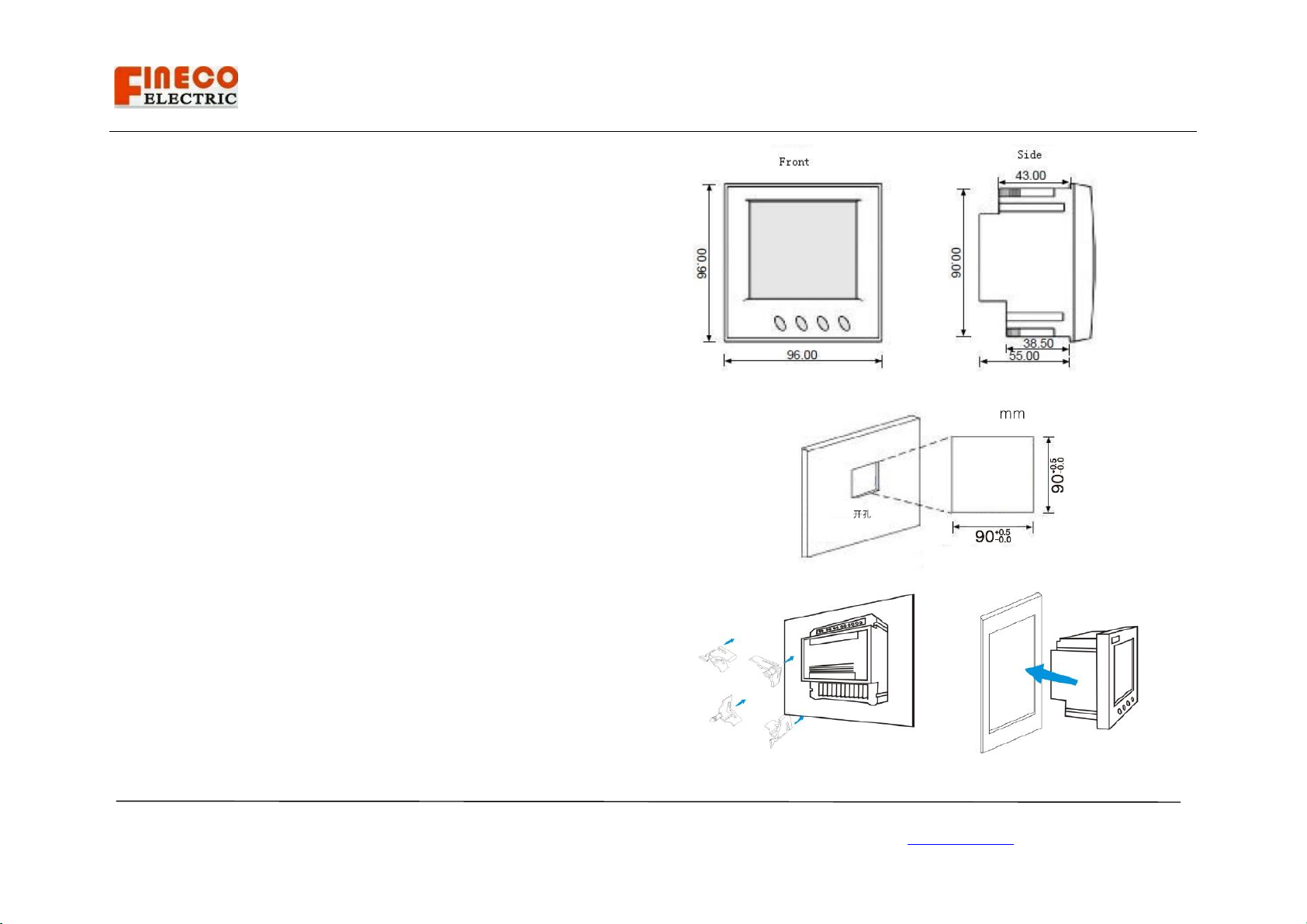
3. Dimensions
Panels should be 1mm to 4mm thick with a square cutout of 90mm(+0.5/0mm)
Insert the meter from the front of the panel, slide the panel clips from the rear
of the case and push firmly against the panel ensuring even pressure on each
clip.

User Manual PM835
Document code: Fineco835-1-1.1 Revision2.001
Shanghai fangqiu electric CO.,LTD. www.fangqiu.com.cn Email: antsmw@163.com
4. Wiring diagrams
Label in the back of the meter
5. Display parameter
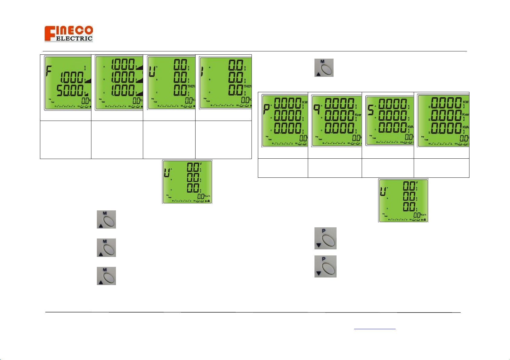
5.1 Phase volts, line volts, phase amps.
Power up , you will see phase volts picture 1.
Step 1, short press ,you will see line volts picture 2.
Step 2, short press , you will see phase amps picture 3.
5.2 System power factor, frequency, phase power factor, volts THD ,amps
THD.
User Manual PM835
Document code: Fineco835-1-1.1 Revision2.001
Shanghai fangqiu electric CO.,LTD. www.fangqiu.com.cn Email: antsmw@163.com
System power
factor and
frequency
(picture 4)
Phase power
factor
(picture 5)
volts Total
Harmonic
Distortion
(picture 6)
amps Total
Harmonic
Distortion
(picture 7)
Power up , you will see phase volts picture 1.
Step 1 , short press , you will see picture 4;
Step 2 , short press , you will see picture 5.
Step 3 , short press , you will see picture 6.
Step 4 , short press , you will see picture 7.
5.3 Phase watts, phase var, phase VA , system power.
Phase watts
(picture 8)
Phase var
(picture 9)
Phase VA
(picture 10)
System power
(picture 11)
Power up , you will see phase volts picture 1
Step 1 , short press , you will see phase watts picture 8;
Step 2 , short press , you will see phase var picture 9;

User Manual PM835
Document code: Fineco835-1-1.1 Revision2.001
Shanghai fangqiu electric CO.,LTD. www.fangqiu.com.cn Email: antsmw@163.com
Step 3 , short press , you will see phase VA picture 10;
Step 4 , short press , you will see system power picture 11.
5.4 kWh /kvarh energy
please short press
(picture 12)
5.5 Time-average volts, Time-average amps, Peak time-average volts, Peak
time-average amps, Peak hold phase volts, Peak hold phase amps.
Time average volts Time average amps Peak time average volts
(picture 13) (picture 14) (picture 15)
Peak time average amps
(picture 16)
Peak hold phase volts
(picture 17)
Peak hold phase amps
(picture 18)
Power up , you will see phase volts picture 1.
Step 1 , long press , you will see picture 13;
Step 2 , short press , you will see picture 14;
Step 3 , short press , you will see picture 15;
Step 4 , short press , you will picture 16;

User Manual PM835
Document code: Fineco835-1-1.1 Revision2.001
Shanghai fangqiu electric CO.,LTD. www.fangqiu.com.cn Email: antsmw@163.com
Step 5 , short press , you will see picture 17;
Step 6 , short press , you will see picture 18.
5.6 Max system power factor and Max frequency, Min system power factor
And Min frequency, Volts Sequence component, Amps sequence component .
Max system
power factor and
Max frequency
(picture 19)
Min system power
factor And Min
frequency (picture
20)
Volts Sequence
component
(picture 21)
Amps sequence
component
(picture 22)
Power up , you will see picture 1.
Step 1 , long press , you will see picture 13 ;
Step 2 , short press , you will see picture 19;
Step 3 , short press , you will see picture 20;
Step 4 , short press , you will see picture 21;
Step 5 , short press , you will see picture 22;
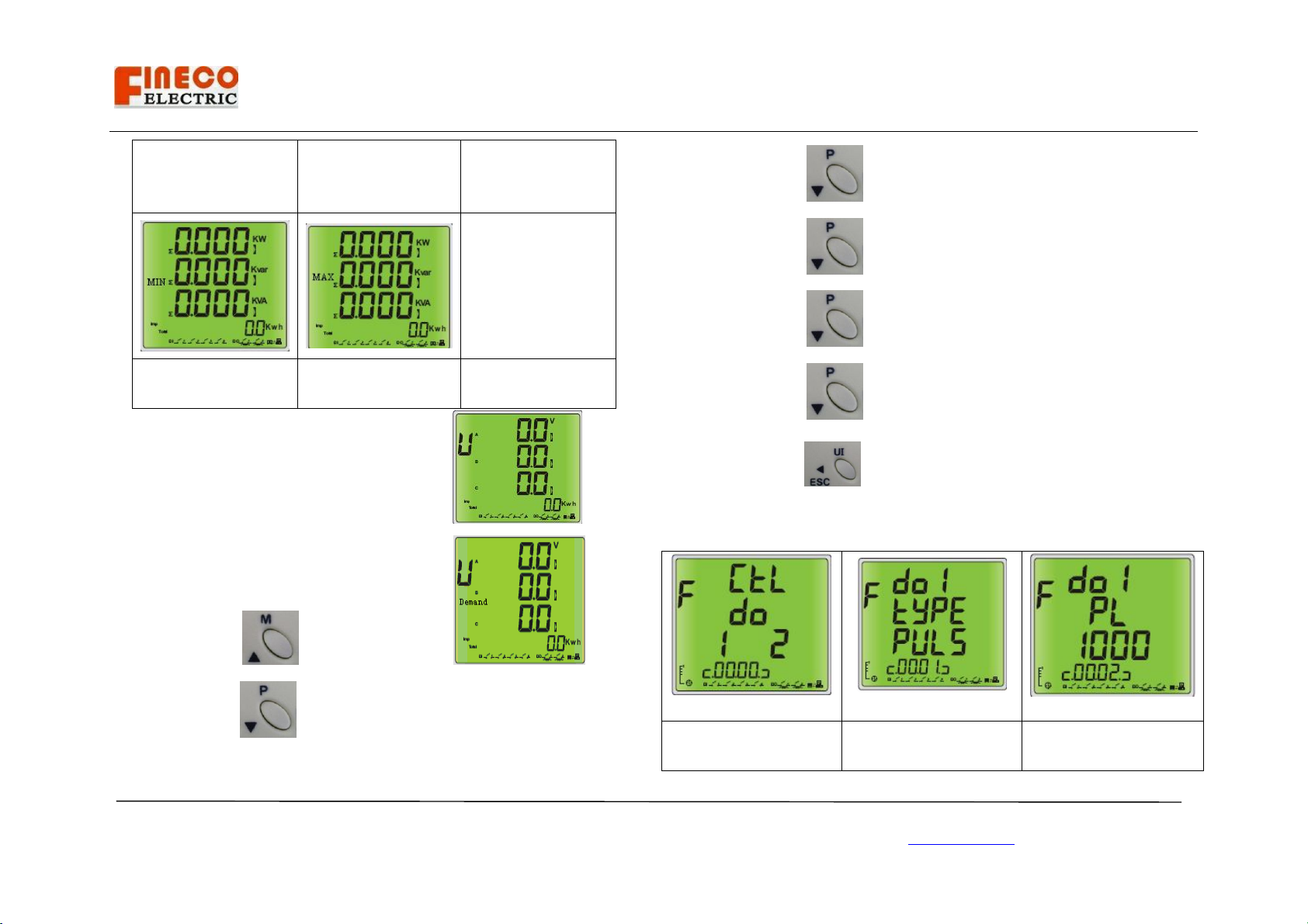
5.7 Power system demand, Min MD, Peak hold MD, Min system power, Max
system power.
User Manual PM835
Document code: Fineco835-1-1.1 Revision2.001
Shanghai fangqiu electric CO.,LTD. www.fangqiu.com.cn Email: antsmw@163.com
Power system
demand
(picture 23)
Min Demand
(picture 24)
Peak hold Demand
(picture 25)
Min system power
(picture 26)
Max system power
(picture 27)
Power up , you will see phase volts picture 1 .
Step 1 , long press , you will see picture 13 ;
Step 2 , short press , you will see picture 23;
Step 3 , short press , you will see picture 24;
Step 4 , short press , you will see picture 25;
Step 5 , short press , you will see picture 26;
Step 6 , short press , you will see picture 27;
If you long press , you will see pictures will auto display one by one.
6. Setting parameter
6.1 Set relays status (parameter 0)
Control output relays
status(picture 30)
Output relay 1 type
Pulse or level(picture
Output relay 1 pulse
width(picture 32)

User Manual PM835
Document code: Fineco835-1-1.1 Revision2.001
Shanghai fangqiu electric CO.,LTD. www.fangqiu.com.cn Email: antsmw@163.com
31)
Output relay 2 type
Pulse or level(picture
33)
Output relay 2 pulse
width(picture 34)
Step 1, long press , enter picture 30;
long press , you can set relays open or close.
Step 2, short press , enter picture 31;
long press , you can set relay 1 type.
Step 3, short press , enter picture 32;
long press , you can set relay1 pulse width.
Step 4, short press enter picture 33;
long press , you can set relay2 type.
Step 5, short press enter picture 34;
Long press ,you can set relay2 pulse width.
Long press you can exit current status……
6.2 Set Modbus ID (parameter 1)

User Manual PM835
Document code: Fineco835-1-1.1 Revision2.001
Shanghai fangqiu electric CO.,LTD. www.fangqiu.com.cn Email: antsmw@163.com
long press , you can set Modbus ID1-254;
6.3 Set RS-485 Baud Rate (parameter 2)
long press , you can set baud rate (1200, 2400, 4800, 9600,
19200, 38400, 115200)
6.4 Set PT , CT (parameter 3-6)
The PT1 can be set 100-500000;
The PT2 can be set 100-400;
The CT1 can be set 1-9999;
The CT2 can be set 1-10.
6.5 Set backlight time (parameter 7)
Backlight time can be set from 5s to 65535s.
6.6 Set auto display time interval (parameter 8)
Time interval can be set from 500ms to 9999ms.
6.7 Clear energy kWh/kvarh
Clear kwh(parameter 9) Clear kvarh(parameter 10)
User Manual PM835
Document code: Fineco835-1-1.1 Revision2.001
Shanghai fangqiu electric CO.,LTD. www.fangqiu.com.cn Email: antsmw@163.com
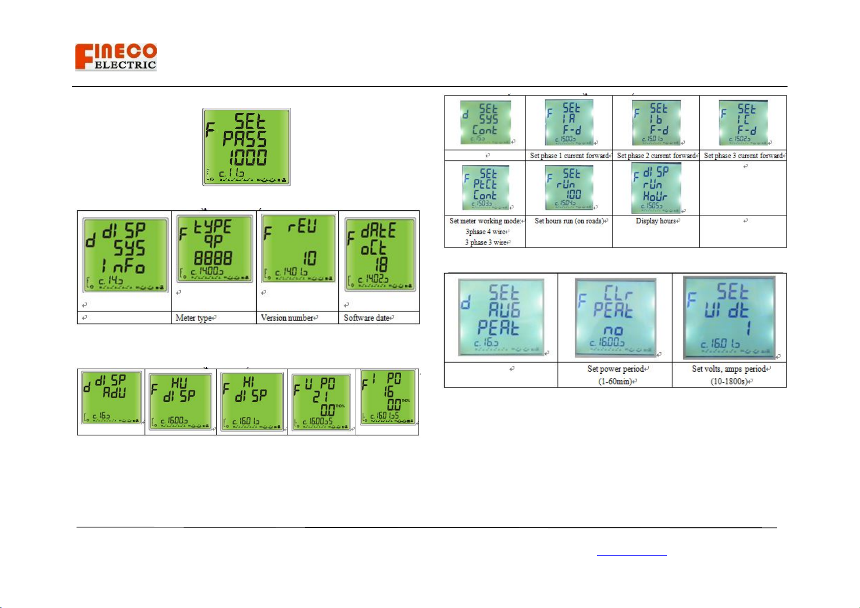
6.8 Set password (parameter 11)
6.9 Panel meter information (parameter 12)
6.10 Individual Harmonic (parameter 14)
6.11 Set System connect status (parameter 15)
6.12 Set volts, amps, power period (parameter 16)
7. Technical support
Any questions, please contact:
TEL: 0086-021-62129691
FAX: 0086-021-62129670
Email: antsmw@163.com
Table of contents
Other Fineco Electric Measuring Instrument manuals


Popular Measuring Instrument manuals by other brands

GPI
GPI 01N31GM-U owner's manual

Green Energy Options
Green Energy Options Solo III Installer's guide

Sunje Hi-Tek
Sunje Hi-Tek SPE-20 instruction manual

Bosch
Bosch Professional GCL 2-50 Original instructions

Extech Instruments
Extech Instruments TachIR RPM10 user guide

Teledyne Lecroy
Teledyne Lecroy PP021 Series user manual


